

Page 1
Technical
Instruction
Benchmark Low NOx Series
AERClean Filtration System Instructions
159 Paris Ave. Northvale, NJ 07647 Phone: 201-768-2400 FAX: 201-768-7789
Doc#
TID-0001-0A
Overview
The AERClean Filtration System assembly (P/N 29161) is available for installation to the combustion intake duct of the the Benchmark Low NOx Series boilers to prevent particulate air-borne
debris from entering the air fuel valve, burner, blower, and other internal components. The AERClean Filtration System is for use in boiler installations drawing air directly from the boiler room.
Advantages of using the filter include:
• Consistent performance in dusty environments.
• Prevention of unnecessary and unplanned service expenses.
• Easily accessed filters for inspection, replacement, or even cleaning.
Installation differs between the 1.5/2.0 and 3.0 models and each is treated seperately in the appropriate section. Optional kits include a pressure gauge and a pressure switch. Several filter options are also available (see page 6).
Base and Optional Kit Part Numbers Tools and Materials Needed
Kit P/N
29161
58034
AERClean Filtration System Kit
Dwyer Magnehelic Pressure Gauge58032
Adjustable Diff. Pressure Switch
Description
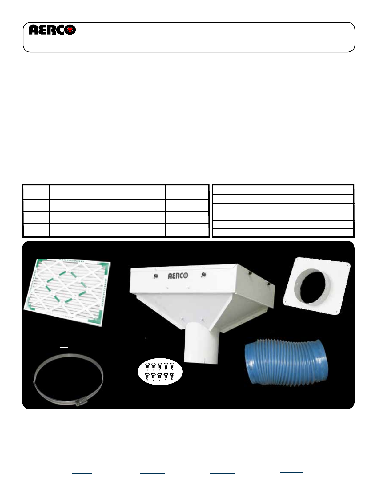
Base AERClean Filtration System Kit P/N 29161
The basic filter assembly kit components are shown below:
SOLD
SEPARATELY
Air Filter
(P/N 87002, 87003,
87004, or 87005)
Filter
Housing
(P/N
39124)
Notes
Base Kit
Optional Kit
Optional Kit
Screwdrivers
Two 2”x 4” wood pieces (8” long)
Socket driver for drill
Drill set for self tapping screws
UL 181 Aluminum tape (BMK1.5/2.0 only)
Tube fittings, Manometer (testing of 58034)
Filter Collar
(P/N 39127)
Hose Clamp
(2 ea) (P/N
123583)
Sheet Metal Screws (10 ea)
(P/N 54010)
Note 1:
The flexible hose (P/N 97004-18) and hose clamp (P/N 123583) are used in the Benchmark 3.0
boiler only, and NOT in the Benchmark 1.5 or 2.0 boilers.
Note 2:
A selection of filter types for varying environmental conditions is available for use in the AERClean
Filtration System. Filters are sold separately. See page 6 for more information.
DOC#: TID-0001-0APage: 1 of 12
Created: 10/13/2010 Revised: 11/11/2010
Flexible Hose
(P/N 97004-18)
Owner: BS-Manager_V.D.
Page 2
Benchmark Low NOx Series
AERClean Filtration System Instructions
BMK3.0LN
Intake Duct Location
Doc#
TID-0001-0A
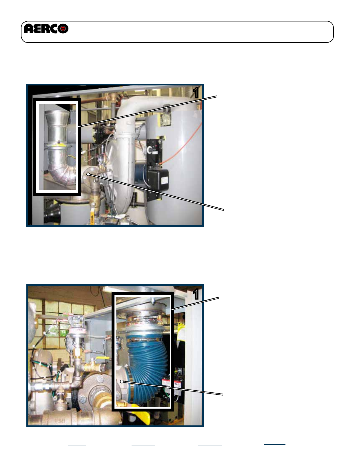
1
In the BMK3.0LN boilers, the
combustion air intake duct as-
sembly is located at rear and be-
low the top surface. It is connect-
ed to the air fuel valve and exits
out of the boiler top section. The
iris-elbow comprises the lower L-
shaped duct which contains the
iris aperature.
Air Fuel Valve
BMK1.5 and BMK2.0 (All Models)
Intake Duct Location
1
In the BMK1.5 and BMK2.0 boil-
ers, the combustion air intake
duct assembly is located at the
front and below the top surface
of the sheet metal top section. It
is connected to the air fuel valve
and exits out of the boiler top
section.
Air Fuel Valve
Page 2
DOC#: TID-0001-0A
Created: 10/13/2010 Revised: 11/11/2010
Owner: BS-Manager_V.D.
Page 3
Benchmark Low NOx Series
AERClean Filtration System Instructions
Benchmark 3.0LN Filter Installation
Doc#
TID-0001-0A
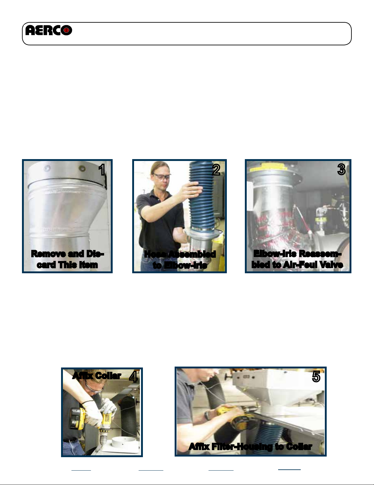
STEP 1:
STEP 2:
STEP 3:
Remove the intake assembly, including iris-elbow and duct/screen assembly from
the air fuel valve of the unit. Remove duct/screen assembly (1) from elbow-iris and
discard.
Slide supplied flexible intake hose over the top section of the elbow-iris and secure it in
place with the supplied 6” hose clamp (2).
Re-attach the elbow-iris/flexible hose assembly back onto the air fuel valve with the orig-
inal hose clamp (3).
1
2
3
Remove and Dis-
card This Item
STEP 4:
STEP 5:
Place lock collar on unit top and position over existing access opening, leaving
space for the reattachment of side access panel. Attach collar to boiler top using
four kit screws (4).
Next, slide the filter housing tube through the collar. Allow sufficient space (over
20”) at front of filter housing to allow easy replacement of air filter through the ac-
cess door. Use four sheet metal screws to attach tube section to the collar (5).
Affix Collar
Hose Assembled
to Elbow-Iris
4
Elbow-Iris Reassem-
bled to Air-Feul Valve
5
Page 3
Affix Filter-Housing to Collar
DOC#: TID-0001-0A
Created: 10/13/2010 Revised: 11/11/2010
Owner: BS-Manager_V.D.
Page 4
Benchmark Low NOx Series
AERClean Filtration System Instructions
Doc#
TID-0001-0A
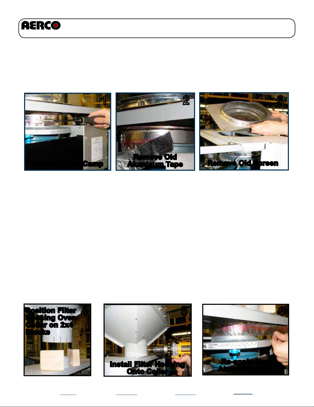
Benchmark 1.5 & 2.0 Filter Installation (All Models)
STEP 1:
Remove Hose-Camp
STEP 2:
Loosen and remove the hose clamp (1) from hose connection and remove
foil tape (2). Remove nuts affixed to existing screen cover and then remove screen
cover from the top of boiler (3).
Insert filter housing into the lock collar. You may use two 2”x4” wood pieces (approx.
8” long) to help keep the filter housing vertically oriented (4), so that collar remains
proper distance above top surface until affixed with screws. Ensure filter is oriented
correctly wirh 20” of clearence in front of the filter access door to enable easy filter
replacement. The air filter assembly also requires at least 2” of headroom above it
for sufficient air intake.
1
Remove Old
Aluminum Tape
2
2
Remove Old Screen
3
STEP 3:
STEP 4:
Position Filter
Housing Over
Collar on 2x4
Blocks
Page 4
Install the filter holder to the lock collar with kit screws (5). Next, slip hose assembly
upward onto collar. It may be a tight fit. Make sure that the 6” hose is not kinked.
After the hose assembly is connected to filter, reapply new aluminum adhesive tape
to seal any leaks (6). Once tape is applied, replace hose clamp and tighten to securely attach hose assembly to the filter housing.
4
DOC#: TID-0001-0A
5
Install Filter Housing
Onto Collar
Created: 10/13/2010 Revised: 11/11/2010
6
Re-apply New
Aluminum Tape
Owner: BS-Manager_V.D.
Page 5

Benchmark Low NOx Series
AERClean Filtration System Instructions
Doc#
TID-0001-0A
Replacing the Filter
The filter is secured in place by two side rails that slide up on an angle to release the filter. To
change the filter, first open the hinged side access door by turning the two PEM fasteners until
they allow the door to swing open. Next, loosen the four wheeled thumb screws on the sides of
the housing and slide the rails up to their high position and lightly tighten them. The filter can now
be removed. If large pieces of debris are on top of filter care must be taken to prevent them from
falling into the boiler. The pleated filter is a disposable item. Replace it only with an AERCO approved replacement filter so that the performance of the boiler is not adversely affected. Ensure
that filter is installed in the correct position for airflow into the boiler. Also be sure to lower the rails
and retighten the screws to properly secure the filter against the gasket.
NOTE: Best practice is to use one of the available pressure measurement gauge options
(see page 7) to indicate when filters need to be changed. Otherwise, it is recommended to
change or clean the filter(s) a minimum of once a year.
Open
(to remove or
replace Filter)
Wheeled
thumb
screws (4
each)
Closed
(to retain fil-
ter in holder)
17
Filter
reatainer
in raised
position
18
Open
Hinged
Access
Door
Ensure that filter is oriented
correctly as shown above.
Page 5
DOC#: TID-0001-0A
Photo above shows filter
NOT installed all the way.
Created: 10/13/2010 Revised: 11/11/2010
Slide filter all the way in until
flush as shown in this photo.
Owner: BS-Manager_V.D.
Page 6

Benchmark Low NOx Series
AERClean Filtration System Instructions
Doc#
TID-0001-0A
Filter Selection Options
The available 16 x 20 panel filters consist of two types of metal reusable filters (which can be
cleaned and then reused) and two disposable pleated panel filters.
The metal filters are specified for use where large debris may be encountered such a leaves and
small airborne construction materials like insulation. There are two types of metal filters; one
made from aluminum and the second made from Stainless Steel (for locations where intake air
might contain elements that could corrode aluminum, such as “salty air” near the shoreline).
The disposable pleated filters are used for filtering out fine dust, like gypsum dust or fine sawdust and are disposable and replaceable and cost less than the permanent metal filters. A hybrid
version of both pleated and metal can be created by installing the 1” metal filter on top of the 1”
pleated filter. This allows for cleaning the top metal filter and replacing the bottom pleated filter
only when it becomes clogged with fine dust to the point where replacement is necessary.
If the type of environment is uncertain, it is recommended that the disposable 2” pleated filter (P/N
87002) be used and replaced when it becomes clogged with dust and debris. The filter housing
assembly is capable of using either 1” filters or 2” filters. Table 1, below, summarizes the filter
selection.
TABLE 1 - Filter Selection
Environment
Small airborne construction
materials (e.g. insulation); other
larger construction debris.
Fine dust (gypsum dust, sawdust,
etc.)
87004 1” Alum.
Filter on Top
87003 1” Pleated
Filter on Bottom
Filter Options
P/N 87004
16” x 20” x 1” Aluminum
P/N 87005
16” x 20” x 1” Stainless Steel
P/N 87003
16” x 20” x 1” Pleated
P/N 87002
16” x 20” x 2” Pleated
P/N 87003
16” x 20” x 1” Pleated
P/N 87002
16” x 20” x 2” Pleated
P/N 87004
16” x 20” x 1” Aluminum
Installed on top of:
P/N 87003
16” x 20” x 1” Pleated
Notes
Re-usable.
Re-usable, Suitable in corrosive environment (“salty” air).
Low cost,
Disposable.
Low cost, Disposable, longer replacement interval than 1”.
Low cost,
Disposable.
Low cost, Disposable, longer replacement interval than 1”.
Extends replacement interval of 1”.
Top aluminum filter is reusable.
Note: DO NOT use 87004 by
itself in these environments.
Uncertain environment type
87005 1” S.S.
Filter on Top
87003 1” Pleated
Filter on Bottom
Page 6
DOC#: TID-0001-0A
P/N 87002
16” x 20” x 2” Pleated
P/N 87005
16” x 20” x 1” Stainless Steel
Installed on top of:
P/N 87003
16” x 20” x 1” Pleated
Created: 10/13/2010 Revised: 11/11/2010
Low cost, Disposable, longer replacement interval than 1”.
Extends replacement interval of 1”.
Top stainless steel filter is reusable
and suitable in corrosive environment (“salty” air).
Note: DO NOT use 87005 by itself
in these environments.
Owner: BS-Manager_V.D.
Page 7

Benchmark Low NOx Series
AERClean Filtration System Instructions
Doc#
TID-0001-0A
Filter Operation Monitoring and Replacement
When used at 100% fire rate, a clean filter will show a differential pressure of ~0.1 inches of water
(0.1” W.C.). As the filter accumulates dust and debris this reading will slowly rise. AERCO recommends the filter be replaced when the gauge reading reaches 0.5” W.C. Since the enclosed 2”
pleated Filter has an effective filtration area of 9.9 square feet, it may take a long time of normal
operation to meet this point. In a dusty environment the need for filter replacement will happen
much sooner.
Optional Pressure Monitoring Kits
The purpose of a pressure gauge or switch is to indicate to the boiler operator when the filter
requires either cleaning or replacement. Changing the filter when the pressure drop across a
clogged filter reaches 0.5” W.C. ensures optimum performance. Two optional kits are available for
use with the base AERClean Filtration System. One of the kits allows visual monitoring of airflow
pressure (Magnehelic pressure gauge), while the other is an ADPS (Adjustable Differential Pressure Switch) allowing an alarm or other user supplied relay device to be tripped when pressure
reaches a user specified level.
Both kit packages come with the necessary components to be installed on the boiler. A bracket is
included to mount the gauge or switch in a location where it can be easily observed and monitored
and enough PVC tubing is included for the device to be located up to six feet (6’) away from air
filter assembly. Also included is the barbed fitting necessary to connect the device’s PVC tubing
to the filter housing assembly.
NOTE:
The information on the following pages is provided only as a guideline for installation and operation of the Dwyer products as supplied as options for the Benchmark Low NOx Filter Kit. Consult the Dwyer website at www.dwyer.com for information regarding specific specifications, maitenance, warranty, service, and troubleshooting of these products. AERCO has provided mounting
brackets, but alternative mounting instruction are available on the Dwyer website.
Page 7
DOC#: TID-0001-0A
Created: 10/13/2010 Revised: 11/11/2010
Owner: BS-Manager_V.D.
Page 8

Benchmark Low NOx Series
AERClean Filtration System Instructions
Doc#
TID-0001-0A
P/N 58032 - Dwyer Magnehelic Differential Pressure Gauge Kit
INTRODUCTION
The Magnehelic® gauge is a high accuracy pressure gauge measuring low air or non-corrosive
gas pressures--either positive, negative (vacuum) or differential. The design resists shock, vibration and over-pressures. It is the industry standard to measure fan and blower pressures, filter resis-
tance, air velocity, furnace draft, pressure drop across orifice plates, liquid levels with bubbler systems
and pressures in fluid amplifier or fluidic systems. It also checks gas-air ratio controls and automatic
valves, and monitors blood and respiratory pressures in medical care equipment.
INSTALLATION
Select a location free from excessive vibration and where the ambient temperature will not exceed
140°F (60°C). Also, avoid direct sunlight which accelerates discoloration of the clear plastic cover.
Sensing lines may be run any necessary distance. Long tubing lengths will not affect accuracy
but will increase response time slightly. Do not restrict lines. If pulsating pressures or vibration
cause excessive pointer oscillation, consult the factory for ways to provide additional damping.
All standard Magnehelic® Differential Pressure Gauges are calibrated with the diaphragm vertical
and should be used in that position for maximum accuracy. If gauges are to be used in other than
vertical position, this should be specified on the order. Many higher range gauges will perform
within tolerance in other positions with only re-zeroing. Low range models of 0.5” w.c. plus 0.25”
w.c. and metric equivalents must be used in the vertical position only.
SURFACE MOUNTING
Locate mounting holes, 120° apart on a 4-1/8” dia. circle. Use No. 6-32 machine screws of appropriate length. Provide a 4-9/16” dia. (116 mm) opening in panel. Provide a 4- 3/4” dia. (120 mm)
opening for MP and HP models. Insert gage and secure in place with No. 6-32 machine screws of
appropriate length, with adapters, firmly secured in place.
TO ZERO GAGE AFTER INSTALLATION
Set the indicating pointer exactly on the zero mark, using the external zero adjust screw on the
cover at the bottom. Note that the zero check or adjustment can only be made with the high and
low pressure taps both open to atmosphere.
OPERATION
Negative Pressure: Connect tubing from source of vacuum or negative pressure to either of the
two low pressure ports. Plug the port not used. Vent one or both high pressure ports to atmosphere.
P/N
67005
54010
91083
97053
33125
Dwyer Magnehelic Diff. Press. Gauge
#10-16 sheet metal screw, 1/2 Long 2
5/16 O.D., 3/16 I.D. PVC Tubing
Dwyer Magnehelic mounting Bracket
Description
3/16” Barbed Fitting
Qty
1
1
1
1
Page 8
DOC#: TID-0001-0A
Created: 10/13/2010 Revised: 11/11/2010
Owner: BS-Manager_V.D.
Page 9

Benchmark Low NOx Series
AERClean Filtration System Instructions
Doc#
TID-0001-0A
Kit P/N 58034 - Dwyer Adjustable Differential Pressure Switch Kit
INTRODUCTION
The Series ADPS Adjustable Differential Pressure Switch enables the closing of an electrical connection at a chosen pressure setting in order to activate an alarm or other relay operated device.
Available settings are from 0.08˝ w.c. (20 Pa) to 16 in w.c. (4000 Pa).
MOUNTING POSITION
Switch should be mounted vertically (pressure connections point down), which allows possible
condensation moisture to drain. If there’s no potential for condensate forming, then switch may be
mounted horizontilly, but only with the electrical connections pointing upwards. In the horizontal
position, the switching values are approximately 0.08 in w.c. (20 Pa) higher as indicated on the
scale.
NOTE:
Switch will NOT function properly if mounted horozontilly with electrical connections point-
ing down.
MOUNTING PROCEDURE
Switch may be mounted onto included bracket (P/N 33125) or directly to a wall or flat surface. If
mounting the switch directly to a surface, use four screws supplied to install through the four outer
monunting lugs. Do not tighten the screws so much that the base of the device is deformed.
Alternately, the switch may also be mounted to a flat surface using the four holes on the rear of the
switch, but ONLY use the screws provided in the kit (not exceeding 5/16 (8mm) in length).
INSTALLING HOSES
Pressure tubing cannot be kinked. Pay particular attention to this point if you run hoses over an
edge. It is better to form a loop. If the hoses are kinked, the device cannot function accurately.
ELECTRICAL CONNECTION
Work on electrical installations must only be carried out by electricians who are specifically trained
for this purpose.
CAUTION:
To avoid a possible fatal electric shock and damage to equipment, ensure there is no
voltage on the connecting cable while you are working on the electrical connections.
For connection to the pressure switch, two fittings on the switch housing are provided for hoses
with an internal diameter of 1/4˝ (6.0 mm). Connect a hose with the higher pressure to socket P1
which is located on the lower (closer to rear) section of the housing. Connect a hose with the lower
pressure to socket P2 which is located on the middle (closer to front) section of the housing. After
you have installed the hoses, it is essential to check for tightness of connection fit, and to ensure
that hoses are not kinked.
Connecting cable can be run from three sides. The screw cable connection has a plug-in design.
The seal is designed only for cables with diameters of 0.275˝ (7 mm) or 0.393˝ (10 mm).
If using a 0.275˝ (7 mm) cable, line up the press nut, plain washer and sealing ring directly on
cable. If using a 0.393˝ (10 mm) cable, you must first break the inner rubber ring out of the sealing
ring directly on the cable, then line up the press nut, plain washer and sealing ring on the cable.
The switching device in this pressure switch is designed as a change-over contact: When pressure is decreasing (NC), pole 3 (COM) closes to Pole 1.
(Continued)
Page 9
DOC#: TID-0001-0A
Created: 10/13/2010 Revised: 11/11/2010
Owner: BS-Manager_V.D.
Page 10

Benchmark Low NOx Series
AERClean Filtration System Instructions
Doc#
TID-0001-0A
Kit P/N 58034 - Dwyer Adjustable Differential Pressure Switch
ELECTRICAL CONNECTION (Cont.)
Protect the feed line (to pole 3) with a fuse, either in control system or along the line as follows:
• 1) Max. 1.5 A / 250 VAC, if you are loading the contact with resistive load.
• 2) Max 0.4 A / 250 VAC, if you are loading the contact with inductive load (such as relay).
• 3) Max. 0.1 A / 250 VDC, if you are using the pressure switch in the weak current version
with gold-plated contacts.
The connections are intended for crimp-type sockets, 0.25 in (6.3 mm):
• Make sure the cable lugs fit properly onto the connections.
• When using rigid copper wire, use cable lugs with mounted screw terminals.
• For flex, it is necessary to crimp on strand end sleeves – and then also screw strands on.
CAUTION:
Ensure there is no voltage on the electrical connections before applying any settings to the
pressure switch.
SETTING THE PRESSURE RANGE
Use the setting screw to set the rotary adjustment to 0.5” w.c.. Note that the indication on the setting screw is only correct for the vertical mounting position. If mounted In the horizontal position,
the switching values are approximately 0.08 in w.c. (20 Pa) higher as indicated on the scale.
CLOSING THE SWITCH
• Insert the screw cable connection into the recess provided for this purpose on the housing.
• Then place the housing cover in position, and screw it down evenly on to the pressure
switch.
TESTING THE SETTING
Partially block the air inlet to test. Insert a “T” into the hose and hook up a nanometer to check for
a trip point of 0.5” w.c.
P/N
60016
54083
54010
91083
97053
33125
Dwyer Differential Pressure Switch
#10-16 sheet metal screw, 1/2 Long 2
5/16 O.D., 3/16 I.D. PVC Tubing
Dwyer Switch Mounting Bracket
Description
#6-32 screw, 5/16 Long
3/16” Barbed Fitting
Qty
1
4
1
1
1
Page 10
DOC#: TID-0001-0A
Created: 10/13/2010 Revised: 11/11/2010
Owner: BS-Manager_V.D.
Page 11

Benchmark Low NOx Series
AERClean Filtration System Instructions
Doc#
TID-0001-0A
WARRANTY
For AERClean Filtration System
The AERClean Air Filtration System for Benchmark Low NOx Boilers is conditionally warranted against
failure for (2) two years from shipment.
AERCO shall accept no responsibility if such item has been improperly installed, operated, or maintained
or if the buyer has permitted any unauthorized modification, adjustment, and/or repairs to the item.
The warranty as set forth on the back page of the Operations & Maintenance Manual is in lieu of and not
in addition to any other express or implied warranties in any documents, or under any law. No salesman
or other representative of AERCO has any authority to expand warranties beyond the face of the said
warranty and purchaser shall not rely on any oral statement except as stated in the said warranty. An Officer of AERCO must do any modifications to this warranty in writing. AERCO MAKES NO WARRANTY OF
MERCHANTABILITY OR FITNESS FOR PARTICULAR PURPOSE OR ANY OTHER EXPRESS OR IMPLIED WARRANTIES. AERCO disclaims all responsibility for any special, incidental or consequential damages. Any
claim relating to the product must be filed with AERCO not later than 14 days after the event-giving rise
to such claim. Any claims relating to this product shall be limited to the sale price of the product at the
time of sale. The sale of the product is specifically conditioned upon acceptance of these terms.
CONDITIONS OF WARRANTY
Should an AERClean Air Filtration System fail for any of the above reasons within the specified time
period from the date of original shipment(s), AERCO shall, at its option, modify, repair or exchange the
defective item. AERCO shall have the option of having the item returned, FOB its factory, or to make
field replacements at the point of installation. In no event shall AERCO be held liable for replacement
labor charges or for freight or handling charges.
AERCO shall accept no responsibility if such item has been improperly installed, operated, or maintained or if the buyer has permitted any unauthorized modification, adjustment, and/or repairs to the
item. The use of replacement parts not manufactured or sold by AERCO will void any warranty, express
or limited.
In order to process a warranty claim, a formal purchase order number is required prior to shipment of
any warranty item. In addition, the warranty must be pre-authorized by AERCO and the returned item
must include a Returned Goods Authorization (RGA) label, attached to the shipping carton, which identifies the item’s return address, register number and factory authorized RGA number.
Page 11
DOC#: TID-0001-0A
Created: 10/13/2010 Revised: 11/11/2010
Owner: BS-Manager_V.D.
Page 12

Benchmark Low NOx Series
AERClean Filtration System Instructions
WATER HEATERS • BOILERS • PARTS & ACCESSORIES
AERCO INTERNATIONAL, INC. • 159 PARIS AVE.
Doc#
TID-0001-0A
NORTHVALE, N.J. 07647-0128 • (201) 768-2400 • FAX 201-768-7789
www.aerco.com
Page 12
DOC#: TID-0001-0A
Created: 10/13/2010 Revised: 11/11/2010
Owner: BS-Manager_V.D.
 Loading...