


Anesthetic Apparatus
Typ Anastazja 7500
0297
User’s Manual
01/2008
14.01.2008
FARUM S.A.
Adres: 74 Jagiellońska street, 03-301 Warszawa,Poland
Heandquarter |
(0-22) 811 14 11 |
Sales Department |
(0-22) 811 06 79 |
Fax. |
(0-22) 811 40 59 |
Tel./Fax. |
(0-22) 811 19 22 |
www.farum.com.pl |
|
|
|

ANASTAZJA 7500 User Manual
User Responsibility
This product will perform in conformity with the description contained in the operating manual and accompanying labels and /or inserts, when assembled, operated, maintained and repaired in accordance with the instructions provided. This product must be checked periodically. Do not use product if defective. Replace all broken, missing, worn, distorted or contaminated parts. If repair or replacement becomes necessary, a telephone call or written request for service advice should be made to the nearest Aeonmed customer service center. This product or any of its parts must be repaired in accordance with the written instructions provided by Aeonmed and by Aeonmed trained personnel. The product must not be altered without the prior written approval of Aeonmed. The user of this product shall assume the full responsibility for any malfunction resulting from improper use, faulty maintenance, improper repair, damage or alteration by anyone other than Aeonmed personnel.
NOTE:
Each FARUM S.A. product has a serial number, such as
Anastazja7500 xxxx-xxxxx
ANASTAZJA 7500: machine model
the first xxxx : the year of manufacturing
the second xx : the month
the third xxx : equipment number
2 |
01/2008 |
Statement
FARUM S.A. holds the copyrights to this manual, which is non-public published, and reserves the rights to keep it as a secure document. Refer to this manual when operating, maintaining and repairing FARUM S.A. products only. Anyone other than FARUM S.A. may not make it known to others.
Proprietary materials protected by the copyright law are included in this manual. Any section of it cannot be reproduced, copied, or translated into other languages without any prior written approval from FARUM S.A. who reserves the copyright.
Everything written in this manual is considered to be correct. FARUM S.A. is not legally responsible for any mistakes printed within and any damages caused by incorrect installation and operation. FARUM S.A. does not supply privileges endowed by the patent law to any other parties. FARUM S.A. is not legally responsible for the results caused by patent law breaking and any rights of the third party violating.
Refer to this manual before any FARUM S.A. product is used. The manual includes operating procedures which must be performed with cautiously, operations that may result in non-normal working conditions and the dangers which may damage equipment or cause bodily harm. FARUM S.A. is not responsible for the security, reliability and function of the equipments in case that the dangers, damages and non-normal phenomenon mentioned in this manual happen. Free repairs for these malfunctions will not be provided by FARUM S.A..
FARUM S.A. have the rights to replace any content in this manual without notice.
Manufacturer Responsibility:
FARUM S.A. is responsible for the security, reliability and function of the equipments when to following conditions are adhered to:
Installation, adjustments, mending and repairs must be performed by individuals authorized by FARUM S.A.;
Necessary electrical equipment and the working environment must be in accordance with the national standards, professional standards and the requirements listed in this manual;
Equipment must be used as instructed in the operating instructions.
CAUTION: This equipment is not for family use.
CAUTION: Malfunctioning equipment may become invalid and cause bodily injury if a set of effective and approving repairing proposals cannot be submitted by the institution which is responsible for using this equipment.
The paid theoretical framework diagram will be supplied according to customer requirements by FARUM S.A., plus calibrating method and other information to help the customer, under the assistance of qualified technicians, repair the equipment parts where can be done by customer himself based on the stipulation by FARUM S.A..
01/2008 |
1 |

ANASTAZJA 7500 User Manual
Warranty:
Manufacturing techniques and materials:
For a period of three months from the date of original delivery, the components and assemblies of this product is warranted to be free from defects manufacturing techniques and materials, provided that the same is properly operated under the conditions of normal use and regular maintenance. The warranty period for other parts is three years. Expendable parts are not included. FARUM S.A. obligation under the above warranties is limited to repairing free of charge.
Free Obligations:
FARUM S.A. obligation under the above warranties does not include the freight and other fees;
FARUM S.A. is not responsible for any direct, indirect or final product broken and delay which result from improper use, alteration by using the assemblies unratified and maintenance by anyone other than FARUM S.A.;
This warranty does not apply to the followings: Improper use
Machines without maintenance or machines broken
The label of FARUM S.A. original serial number or mark is removed or replaced Other manufacturers’ product
Security, reliability and operating condition:
FARUM S.A. is not responsible for the security, reliability and operating condition of this product in case that:
The assemblies are disassembled, extended and readjusted
This product is not operated correctly in accordance with the manual instruction. The power supply used or operating environment does not follow the requirements in this manual.
2 |
01/2008 |
Return
Follow the steps in case that the product needs to be returned to FARUM S.A.:
1. Obtain the rights of return
Contact with the customer service of FARUM S.A. by informing them the number and type of the product. The number is marked on the surface of the product. Return is unacceptable if the number cannot be identified. Enclose a statement of the number, type and the reason of return as well.
2. Transportation charges
Transportation and insurance charges must be prepaid by the user for transporting the product to FARUM S.A. for repairing. (Customers charges is added with regard to the products sold to non-Chinese mainland users)
01/2008 |
3 |
Contents
STATEMENT |
............................................................................................................................... |
1 |
||
1 |
INTRODUCTION............................................................................................................... |
1-1 |
||
|
1.1 |
WHAT’S ANASTAZJA 7500?.............................................................................................. |
1-1 |
|
|
1.1.1 |
Range for used ......................................................................................................... |
1-1 |
|
|
1.2 |
SYMBOLS USED IN THE MANUAL AND IN THE EQUIPMENT ...................................................... |
1-3 |
|
2 |
ANESTHETIC SYSTEM CONTROL ................................................................................ |
2-1 |
||
|
2.1 |
ANESTHETIC SYSTEM.......................................................................................................... |
2-1 |
|
|
2.2 |
THE BREATHING SYSTEM MODULE ....................................................................................... |
2-5 |
|
|
2.2.1 |
Absorber cycle.......................................................................................................... |
2-7 |
|
|
2.2.2 |
Bellows Assembly................................................................................................... |
2-10 |
|
|
2.3 |
VAPORIZER CONTROL....................................................................................................... |
2-11 |
|
|
2.4 |
VENTILATOR CONTROL...................................................................................................... |
2-11 |
|
|
2.4.1 |
Front Panel ............................................................................................................. |
2-11 |
|
|
2.4.2 |
Keys........................................................................................................................ |
2-12 |
|
|
2.4.3 |
Indicators ................................................................................................................ |
2-12 |
|
|
2.4.4 |
Knob ....................................................................................................................... |
2-12 |
|
|
2.4.5 |
Display Screen........................................................................................................ |
2-13 |
|
|
2.4.6 |
Rear Panel.............................................................................................................. |
2-15 |
|
|
2.5 |
MENU .............................................................................................................................. |
2-17 |
|
|
2.5.1 |
Operating Guide ..................................................................................................... |
2-17 |
|
|
2.5.2 |
Menu diagram......................................................................................................... |
2-20 |
|
3 |
OPERATING GUIDE......................................................................................................... |
3-1 |
||
|
3.1 |
STARTING SYSTEM ............................................................................................................. |
3-1 |
|
|
3.1.1 |
Alarm Limit Set ......................................................................................................... |
3-3 |
|
|
3.1.2 |
Restore Default Set .................................................................................................. |
3-6 |
|
|
3.1.3 |
Ventilation Mode Set................................................................................................. |
3-9 |
|
|
3.1.4 |
Ventilator Control Set.............................................................................................. |
3-10 |
|
|
3.2 |
STARTING AUTO VENTILATION ........................................................................................... |
3-11 |
|
|
3.3 |
SHUTTING OFF AUTO VENTILATION.................................................................................... |
3-12 |
|
|
3.4 |
ALARM ............................................................................................................................. |
3-13 |
|
|
3.4.1 |
Alarm tone .............................................................................................................. |
3-13 |
|
|
3.4.2 |
Alarm Silence.......................................................................................................... |
3-13 |
|
|
3.5 |
WAVEFORM ...................................................................................................................... |
3-14 |
|
4 |
PREOPERATIVE CHECKOUT......................................................................................... |
4-1 |
||
|
4.1 |
ANASTAZJA7500 PREOPERATIVE CHECKOUT PROCEDURES.................................................. |
4-1 |
|
|
4.1.1 |
System Checkout ..................................................................................................... |
4-2 |
|
|
4.1.2 |
Mains failure alarm test ............................................................................................ |
4-2 |
|
|
4.2 |
TESTING THE GAS SUPPLY PIPELINE AND THE GAS CYLINDER ................................................. |
4-3 |
|
|
4.3 |
MONITORING FLOW CONTROL............................................................................................. |
4-5 |
|
|
4.3.1 |
Monitoring without oxygen........................................................................................ |
4-5 |
|
|
4.3.2 |
Monitoring with Oxygen............................................................................................ |
4-7 |
|
|
4.4 |
INSTALLING AND TESTING OF VAPORIZER .............................................................................. |
4-9 |
|
|
4.4.1 |
Installation................................................................................................................. |
4-9 |
|
|
4.4.2 |
Testing Vaporizer Back Pressure ............................................................................. |
4-9 |
|
|
4.5 |
TESTING ALARM................................................................................................................ |
4-10 |
|
|
4.6 |
TESTING THE BREATHING SYSTEM..................................................................................... |
4-12 |
|
|
4.6.1 |
Checking Oxygen flush Switch............................................................................... |
4-12 |
|
|
4.6.2 |
Testing Breathing System....................................................................................... |
4-12 |
|
|
4.6.3 |
Testing APL Valve................................................................................................... |
4-12 |
|
|
4.7 |
TESTING VENTILATOR ....................................................................................................... |
4-13 |
|
|
|
|
01/2008 |
i |

ANASTAZJA 7500 User Manual
5 |
INSTALLING AND CONNECTING................................................................................... |
5-1 |
||
|
5.1 |
INSTALLING PRODUCT ......................................................................................................... |
5-2 |
|
|
5.1.1 |
Shelf.......................................................................................................................... |
5-2 |
|
|
5.1.2 |
Breathing circuit limb ................................................................................................ |
5-2 |
|
|
5.1.3 |
Absorber cycle.......................................................................................................... |
5-2 |
|
|
5.1.4 |
The bellows Assembly base ..................................................................................... |
5-2 |
|
|
5.2 |
INSTALLING ABSORBER ....................................................................................................... |
5-3 |
|
|
5.2.1 |
When to replace absorbent ...................................................................................... |
5-3 |
|
|
5.2.2 |
Disassembling Absorber........................................................................................... |
5-4 |
|
|
5.2.3 |
Filling Absorbent ....................................................................................................... |
5-4 |
|
|
5.3 |
CONNECTING TUBES AND LINES ........................................................................................... |
5-5 |
|
|
5.4 |
CONNECTING GAS AND ELECTRICITY ................................................................................... |
5-6 |
|
|
5.4.1 |
AC inlet ..................................................................................................................... |
5-6 |
|
|
5.4.2 |
Auxiliary mains socket outlet .................................................................................... |
5-7 |
|
|
5.4.3 |
Serial Port ................................................................................................................. |
5-7 |
|
|
5.4.4 |
Pipeline gas supply inlet ........................................................................................... |
5-8 |
|
|
5.4.5 |
Cylinder gas supply inlet........................................................................................... |
5-8 |
|
|
5.5 |
HOW TO INSTALL GAS CYLINDER (TESTING HIGH PRESSURE LEAK) ......................................... |
5-9 |
|
|
5.6 |
CONNECT GAS SCAVENGING TRANSFER & RECEIVING SYSTEM............................................. |
5-10 |
|
6 |
CLEANING AND STERILIZING....................................................................................... |
6-1 |
||
|
6.1 |
CLEANING AND STERILIZATION OF PRE-USE FIRST ................................................................. |
6-2 |
|
|
6.2 |
CLEANABLE BREATHING SYSTEM COMPONENTS................................................................... |
6-2 |
|
|
6.3 |
ABSORBER ......................................................................................................................... |
6-3 |
|
|
6.3.1 |
Auto cleaning with agent or disinfector..................................................................... |
6-3 |
|
|
6.3.2 |
Manual cleaning........................................................................................................ |
6-3 |
|
|
6.3.3 |
Advanced Sterilizing ................................................................................................. |
6-3 |
|
|
6.4 |
ABSORBER ASSEMBLY......................................................................................................... |
6-4 |
|
|
6.5 |
THE BELLOWS ASSEMBLY.................................................................................................... |
6-4 |
|
|
6.5.1 |
Disassembling .......................................................................................................... |
6-5 |
|
|
6.5.2 |
Testing Function........................................................................................................ |
6-8 |
|
|
6.5.3 |
Assembly lists ......................................................................................................... |
6-10 |
|
|
6.5.4 |
Cleaning and Sterilizing.......................................................................................... |
6-11 |
|
|
6.5.5 |
Regular Maintenance.............................................................................................. |
6-12 |
|
7 |
USER MAINTENANCE..................................................................................................... |
7-1 |
||
|
7.1 |
REPAIR POLICY................................................................................................................... |
7-1 |
|
|
7.2 |
MAINTAINING OUTLINE AND SCHEDULE ................................................................................ |
7-2 |
|
|
7.2.1 |
User maintenance..................................................................................................... |
7-2 |
|
|
7.2.2 |
Permissive Repairing................................................................................................ |
7-2 |
|
|
7.2.3 |
Useful life estimation................................................................................................. |
7-3 |
|
|
7.3 |
MAINTAINING THE BREATHING SYSTEM ................................................................................ |
7-3 |
|
|
7.3.1 |
Replace O2 sensor.................................................................................................... |
7-3 |
|
|
7.3.2 |
Calibrate O2 sensor .................................................................................................. |
7-4 |
|
|
7.3.3 |
Calibrate flow sensor .............................................................................................. |
7-11 |
|
|
7.3.4 |
Calibrate flow valve................................................................................................. |
7-14 |
|
|
7.4 |
MAINTAINING OXYGEN SENSOR.......................................................................................... |
7-15 |
|
|
7.4.1 |
Technical requirements........................................................................................... |
7-15 |
|
|
7.4.2 |
Recommended O2 sensor ...................................................................................... |
7-15 |
|
|
7.5 |
REPLACING FUSES............................................................................................................ |
7-16 |
|
|
7.5.1 |
Replacing fuse of mains supply.............................................................................. |
7-16 |
|
|
7.5.2 |
Replacing fuse of auxiliary mains socket outlets.................................................... |
7-17 |
|
|
7.5.3 |
Replacing fuse of ventilator .................................................................................... |
7-17 |
|
|
7.6 |
MAINTAINING BATTERY ...................................................................................................... |
7-18 |
|
8 |
ALARM AND TROUBLESHOOTING............................................................................... |
8-1 |
||
|
8.1 |
ABOUT ALARM..................................................................................................................... |
8-1 |
|
|
8.2 |
ALARM MESSAGE LIST ......................................................................................................... |
8-2 |
|
|
8.2.1 |
Technical alarm......................................................................................................... |
8-2 |
|
ii |
01/2008 |
8.2.2 |
Functional alarm ....................................................................................................... |
8-3 |
|
8.3 |
TROUBLESHOOTING............................................................................................................ |
8-4 |
|
8.3.1 |
Anesthesia machine troubleshooting and analyzing ................................................ |
8-4 |
|
8.3.2 |
MV300 Troubleshooting and Analyzing .................................................................... |
8-5 |
|
8.4 |
DEFAULT SETTING............................................................................................................... |
8-6 |
|
9 ACCESSORIES ................................................................................................................ |
9-1 |
||
9.1 |
THE BREATHING SYSTEM..................................................................................................... |
9-1 |
|
9.2 |
THE ABSORBER ASSEMBLY ................................................................................................. |
9-1 |
|
9.3 |
OTHERS............................................................................................................................. |
9-2 |
|
10 |
SPECIFICATIONS AND OPERATION THEORY ....................................................... |
10-1 |
|
10.1 |
GAS CIRCUIT OF ANASTAZJA 7500 ................................................................................. |
10-1 |
|
10.2 |
SYSTEM TECHNICAL SPECIFICATION ................................................................................... |
10-3 |
|
10.2.1 |
Drive ....................................................................................................................... |
10-3 |
|
10.2.2 |
Flow ........................................................................................................................ |
10-3 |
|
10.2.3 |
Classification........................................................................................................... |
10-4 |
|
10.3 |
POWER SUPPLY ................................................................................................................ |
10-4 |
|
10.3.1 |
Power cord.............................................................................................................. |
10-5 |
|
10.4 |
ELECTROMAGNETIC COMPATIBILITY ................................................................................... |
10-5 |
|
10.5 |
PHYSICAL SPECIFICATION................................................................................................ |
10-10 |
|
10.6 |
ENVIRONMENT REQUIREMENTS ....................................................................................... |
10-10 |
|
10.7 |
BREATHING SYSTEM TECHNICAL SPECIFICATIONS.............................................................. |
10-11 |
|
10.8 |
ANESTHESIA VENTILATOR................................................................................................ |
10-12 |
|
10.8.1 |
Operation Theory.................................................................................................. |
10-12 |
|
10.8.2 |
Performance of ventilator ..................................................................................... |
10-13 |
|
10.8.3 |
Setting ventilation mode ....................................................................................... |
10-14 |
|
10.8.4 |
Setting ventilating parameters.............................................................................. |
10-14 |
|
10.8.5 |
Gas dynamics performance.................................................................................. |
10-14 |
|
10.8.6 |
Setting alarm parameters ..................................................................................... |
10-15 |
|
10.8.7 |
Volume.................................................................................................................. |
10-15 |
|
10.8.8 |
Monitoring performance........................................................................................ |
10-16 |
|
10.8.9 |
O2 monitoring specification................................................................................... |
10-17 |
|
01/2008 |
iii |
1 Introduction
1.1What’s ANASTAZJA 7500?
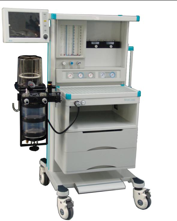
ANASTAZJA 7500 is a compact and integrated anesthesia transmitting system. The breathing machine not only provides patients in operation with auto ventilation, but also monitors and displays the patient’s various parameters. The ventilator used in the system is controlled by a microprocessor.
The anesthetic ventilator controlled by microprocessor of ANASTAZJA 7500 includes monitor internally, volume mode, and other functions optional. It can be used for communication with cardiac blood vessel and monitor of breathing gas by serial interface.
Not all the optional functions available may be included in the manual. It is also possible to add other equipment to the top or middle of this system for added functions. For more information with respect to the existing product, please feel free to contact the local representatives.
 WARNING: The user of ANASTAZJA 7500 must be professional and trained.
 WARNING: ANASTAZJA 7500 is unsuitable for use in a magnetic resonance imaging (MRI) environment.
1.1.1Range for used
ANASTAZJA 7500 is applicable for patients of over 25 Kg with standard set and for child of over 12 Kg with cycles and CO2 monitoring device of child.
 WARNING: ANASTAZJA 7500 is not to be used with infant.
01/2008 |
1-1 |
ANASTAZJA 7500 User Manual
Figure 1-1 ANASTAZJA 7500
1-2 |
01/2008 |
1 Introduction
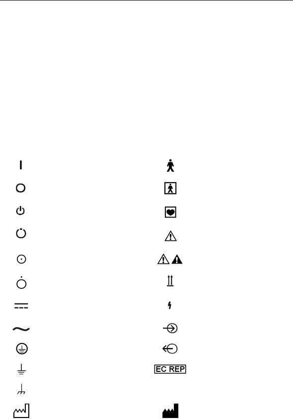
1.2Symbols Used in the Manual and in the Equipment
 Warnings and
  Cautions indicate all the possible dangers in case of violation of the stipulations in this manual. Refer to and follow them.
 WARNING: indicates potential hazards to operators or patients
 CAUTION: indicates potential damage to equipment
Instead of illustrations, other symbols may also be utilized. Not all of them may necessarily appear in the equipment and manual. The symbols include:
 CAUTION: This manual complies with EN 1041.
ON Power |
|
Type B equipment |
OFF Power |
|
Type BF equipment |
Stand-by |
|
Type CF equipment |
Stand-by or preparatory state |
|
Warning or Caution, ISO |
for a part of the equipment |
|
7000-0434 |
ON only for part of the |
|
NOTE: refer to the manual, |
equipment |
|
IEC601-1 |
OFF only for part of the |
|
This way up |
equipment |
|
|
|
|
|
Direct Current |
|
Dangerous Voltage |
Alternating Current |
|
Input |
Protectively earth |
|
Output |
Earth |
|
CE Representative |
Frame or chassis ground |
SN |
Serial Number |
Date of manufacture |
|
Address of manufacture |
01/2008 |
1-3 |
ANASTAZJA 7500 User Manual
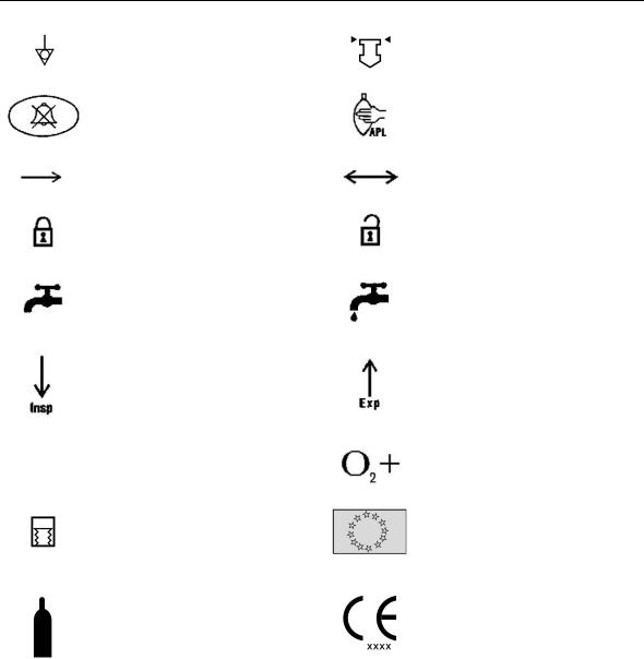
Equipotential
Alarm Silence
Movement in one direction
Lock
Close drain valve
Inspiration flow
134ºc Autoclavable
Auto ventilation
Gas cylinder
View the reading on the top of float
Reservoir bag location/manual ventilation
Movement in two directions
Unlock
Open drain valve (release liquid)
Expiration flow
Oxygen flush
CE Representative
The system, with this label under the stipulations in the operating manual, complies with the requirements related from 93/42/EEC. xxxx is the certificate number used by FARUM S.A. quality system to certify authorizations
1-4 |
01/2008 |
2 Anesthetic System Control
2.1Anesthetic system
 CAUTION: The anesthetic system is intended to be used with the following monitoring devices, alarm systems, and protection devices:
--pressure measuring in accordance with 8.1 of ISO 8835-2;
--pressure limitation device in accordance with 51.101.1 of IEC60601-2-13;
--exhaled volume monitor in accordance with 51.101.4 of IEC60601-2-13;
--breathing system integrity alarm system in accordance with 51.101.5 of IEC60601-2-13;
--continuing pressure alarm in accordance with 51.101.6 of IEC60601-2-13;
--O2 monitor in accordance with ISO 9918.
 WARNING: To avoid explosion hazards, flammable anesthetic agents such as ether and cyclopropane shall not be used in this anesthetic workstation. Only anesthetic agents which comply with the requirements for non-flammable anesthetic agents as specified in this manual.
Halothane, desflurane, sevoflurane, enflurane,and isoflurane have been found to be non-flammable agents.
 WARNING: Independent means of ventilation (e.g. a self-inflating manually powered resuscitator with mask) should be available whenever the anesthetic system is in use.
 WARNING: Do not use antistatic or electrically-conductive breathing tubes and mask.
 WARNING: Leakage and douse of liquid, such as anesthetic agent, bring on dangerous states or malfunctions inside device.
01/2008 |
2-1 |

ANASTAZJA 7500 User Manual
|
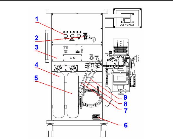
Figure 2-1 ANASTAZJA 7500 (front view) |
||
1 |
Drawer |
2 |
Reservoir Bag |
3 |
Oxygen Flush |
4 |
Absorber cycle |
5 |
Common Gas Outlet |
6 |
Air pipeline pressure gauge |
7 |
N2O pipeline pressure gauge |
8 |
O2 pipeline pressure gauge |
9 |
Autoclavable Bellows Assembly |
10 |
Flowmeters |
11 |
Display Screen of anesthetic |
12 |
Enflurane Vaporizer |
ventilator |
|||
13 |
Isoflurane Vaporizer |
14 |
O2 cylinder pressure gauge |
15 |
N2O cylinder pressure gauge |
|
|
Figure 2-1 each control function on the front view of Anastazja7500
|
Item |
Diagram |
Description |
|
|
|
|
|
|
|
Press Oxygen Flush button to |
3 |
Oxygen Flush |
supply O2 to the breathing system |
|
|
|
|
with high flow rate |
|
|
|
|
5 |
Common |
gas |
connects the anesthesia machine to |
outlet |
|
the breathing system |
|
|
|
||
|
|
|
|
2-2 |
01/2008 |
|
|
2 Anesthetic System Control |
|
|
|
|
|
|
|
|
|
|
|
Turn the knob counterclockwise to |
|
|
|
increase the flow; turn clockwise to |
|
|
10 Flow Control |
decrease the flow. |
|
|
|
Read top of float when the |
|
|
|
flowmeter is being read. |
|
|
|
|
|
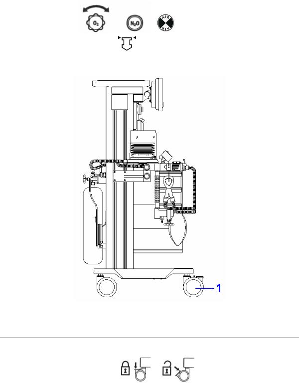
Figure 2-2 ANASTAZJA 7500 (side view)
Figure 2-2 each control function on the side view of Anastazja7500
Item |
Diagram |
Description |
|
|
|
|
|
1 |
Castor with break |
Push down to lock, and |
|
pull up to unlock. |
|||
|
|
||
|
|
|
01/2008 |
2-3 |
ANASTAZJA 7500 User Manual
|
Figure 2-3 Anastazja7500 (back view) |
||
1 |
Auxiliary mains socket outlet |
2 |
Power socket |
3 |
Anesthetic ventilator unit |
4 |
N2O cylinder |
5 |
O2 cylinder |
6 |
Nameplate |
7 |
Air pipeline |
8 |
N2O pipeline |
9O2 pipeline
2-4 |
01/2008 |
2 Anesthetic System Control
2.2The Breathing system module
 CAUTION: Any adult anesthetic ventilator system used together with the anesthetic gas supply system must be in accordance with ISO 8835-2.
Figure 2-4 Breathing system module
1Absorber mount release handle
2Absorber (Carbon dioxide absorbent)
3 Exhalation Port / patient circuit connector
4Exhalation valve
5Airway pressure gauge
6 Bellows assembly (auto ventilation)
7 APL (adjustable pressure limit) valve
8Inhalation valve
9 Manual reservoir bag/auto ventilation switch
10Inhalation Port/Patient circuit port
11Manual reservoir bag port
01/2008 |
2-5 |
ANASTAZJA 7500 User Manual
Figure 2-4 the breathing system components function control
Item |
Diagram |
Description |
|
|
|
2 |
Absorber |
mount |
release |
|
|
|
|
|
|
|
Two soda lime canisters are |
|
|
applied with a volume of 1500 |
|
|
ml for each so that it can be |
|
|
continuously used for 6-8 hours |
|
|
at full load. The water from the |
|
|
reaction is drained via the |
|
|
water collector underneath. |
|
|
Adjust the pressure limit of |
||||
|
|
the |
breathing |
|
system |
|
|
|
during |
|
the |
|
manual |
|
|
ventilation |
process. The |
|||
|
|
readings are approximate. |
||||
|
|
The |
colors |
represent |
||
7 |
APL valve |
different pressure |
zones. |
|||
|
|
Green |
represents |
safety |
||
|
|
zone; |
yellow represents |
|||
|
|
transition |
zone; |
red |
||
|
|
represents |
high |
pressure |
||
|
|
zone. |
Adjusting |
ranges |
||
|
|
between 0.19-6 kPa. |
||||
|
|
|
Auto ventilation “off” gas into |
|
|
|
|
reservoir bag |
|
|
Manual |
reservoir |
Select manual |
ventilation |
9 |
bag/auto |
ventilation |
(reservoir bag) |
or auto |
|
switch |
|
ventilation (ventilator). |
|
Auto ventilation “on” gas into bellows
2-6 |
01/2008 |
2 Anesthetic System Control
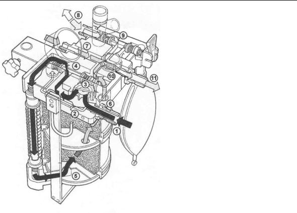
2.2.1Absorber cycle
2.2.1.1Structure
The functions of absorber cycle: absorb carbon dioxide; vent exhaust gas; assistant respiration; monitor airway pressure; drain water generated by chemistry etc.
|
|
|
|
|
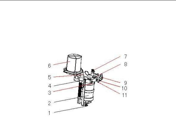
Figure 2-5 Absorber cycle |
||
1. APL valve |
7. |
Lower absorber |
|
2. |
Inhalation valve |
8. |
Upper absorber |
3. |
Inspiratory port |
9. |
Expiratory port |
4. |
Bag/Ventilator Switch |
10. Exhalation valve |
|
5. |
Reservoir Bag |
11. |
Fixation module |
6. |
Handle |
12. Airway Pressure Gauge |
|
2.2.1.2Principle
Gas flow schematic diagram, see Figure 2-6.
01/2008 |
2-7 |
ANASTAZJA 7500 User Manual
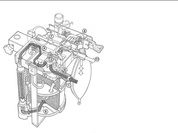
Bag operating
1-Expiratory gas of patient;
2-Sampling airway pressure;
3-via exhalation valve (unidirectional);
4-bypass switch (normal close);
5-enter into absorber;
6-leave absorber;
7-fresh gas compensation;
8-Bag/Ventilator (Bag ”ON”);
9-APL valve sampling path;
10via exhalation valve; (unidirectional);
11-Inspiratory gas
2-8 |
01/2008 |
2 Anesthetic System Control
Ventilator operating
1-Expiratory gas of patient;
2-Sampling airway pressure;
3-via exhalation valve (unidirectional);
4-bypass switch (normal close);
5-enter into absorber;
6-leave absorber;
7-fresh gas compensation;
8-gas of patient
9- Bag/Ventilator (Bag ”OFF”);
10via exhalation valve; (unidirectional);
11Inspiratory gas
Figure 2-6 Gas flow schematic diagram
01/2008 |
2-9 |
ANASTAZJA 7500 User Manual
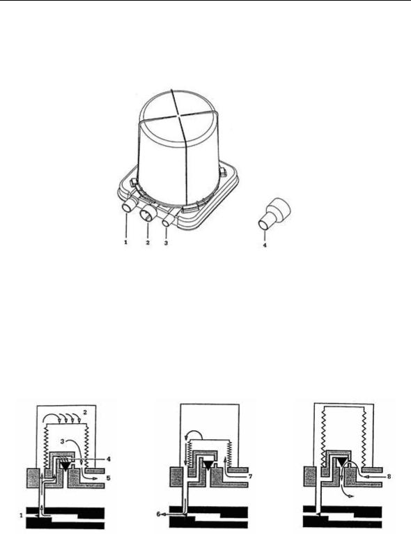
2.2.2Bellows Assembly
2.2.2.1Ports
Figure 2-7 Ports of bellows assembly
1 Breathing system connector 2 Exhaust gas port 3 Driven gas connector 4 Adapter
 WARNING: Never connect exhaust gas port with sub-atmospheric system directly. Or else leakage of breathing system generates.
The adapter can be used to connect the waste gas scavenging system to the bellows assembly if the standard pipeline is used in the waste gas scavenging system.
2.2.2.2ventilating circulation
Inhalation primary phase: |
Exhalation primary phase: |
Exhalation end phase: |
||
1 |
Exhalation valve |
6 |
Driving gas |
8 Excess gas of patient |
2 |
Driving gas |
7 |
From patient circuit |
circuit |
|
||||
3 |
Gas of patient circuit |
|
|
|
4 |
Spill-over valve |
|
|
|
5 To patient circuit
2-10 |
01/2008 |
2 Anesthetic System Control
2.3Vaporizer Control
Refer to operating and maintenance manual of vaporizer for more details.
 WARNING: Anesthetic vapour delivery device used with anesthetic system must be in accordance with ISO 8835-4.
2.4Ventilator Control
 CAUTION: Anesthetic ventilator accords with ISO 8835-5.
 CAUTION: Monitoring conditions of this system: Ambient temperature: 29;
Air temperature: 30;Air humidity: 30%; Gas component: Oxygen.
 CAUTION: If the temperature of sensor is lower than dew point of breathing gas, vapour may coagulate on the surface of sensor, and oxygen concentration monitored may be lower than practice value.
Optional function: SIMV mode, P-V loop and V-Flow loop can be added by code.
2.4.1Front Panel
Front panel consists of display screen, keys, indicators, and a knob.
Figure 2-8 Front Panel
01/2008 |
2-11 |
ANASTAZJA 7500 User Manual
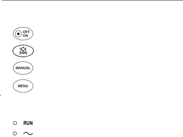
2.4.2Keys
|
|
Mains switch key |
Press the key and hold on for 2 second, you |
|
|
can start or shut off ventilator. |
|
|
|
|
|
|
|
|
|
|
|
Alarm silence key |
Press the key, alarm mutes for 110 seconds. |
|
|
|
|
|
|
|
Press the key, change original ventilation |
|
|
Manual mode key |
mode to manual mode; Press again, back to |
|
|
|
the original ventilation mode. |
|
|
|
|
|
|
|
Press the key, a “Menu” window appeared on |
|
|
Menu key |
the display screen, more details refer to |
|
|
|
section 2.5. |
|
|
|
|
2.4.3 |
Indicators |
|
|
|
|
Running Indicator |
The indicator brightly as ventilator operating. |
|
|
AC Indicator |
The indicator brightly as AC power effectively; |
|
|
|
The indicator dark as AC power failure. |
2.4.4Knob
The user may use the rotary knob to select the menu item and modify the setup. It can be rotated clockwise or counter-clockwise and pressed like other buttons. The user may use the knob to realize the operations on the screen and in the system menu and parameter menu.
The rectangular mark on the screen that moves with the rotation of the knob is called “cursor”. Operation can be performed at any position at which the cursor can stay.
Operating method:
Move the cursor to the item where the operation is wanted
Press the knob
One of the following four situations may appear:
The background color of cursor may become into the contrast color, which implies that the content in the frame can change with the rotation of the knob.
Pull down menu or dialogue box may appear on the screen, or the original menu is replaced by the new menu.
Save setup.
2-12 |
01/2008 |
2 Anesthetic System Control
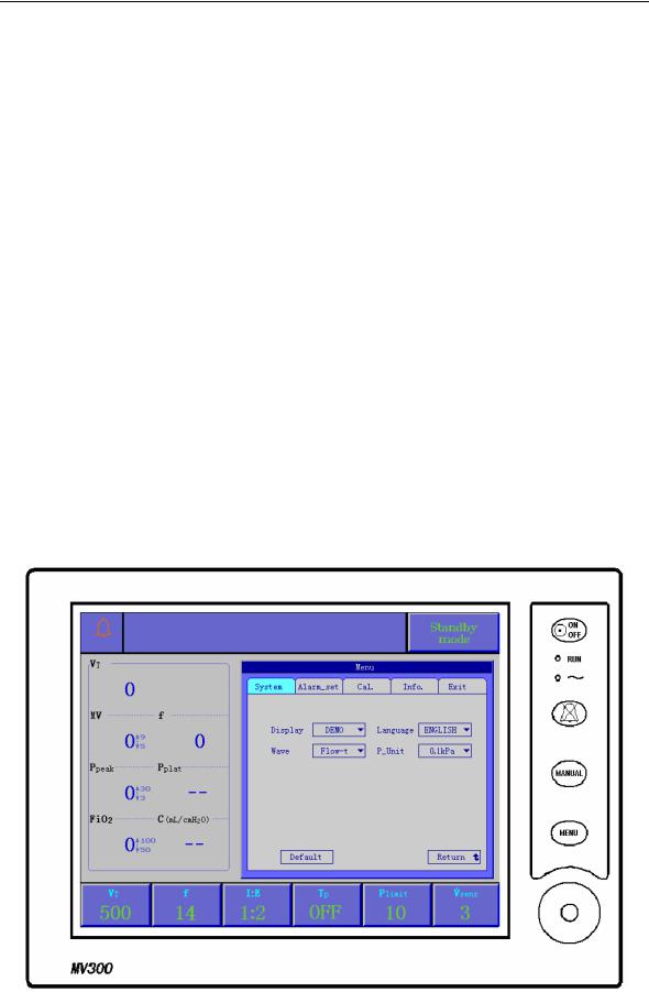
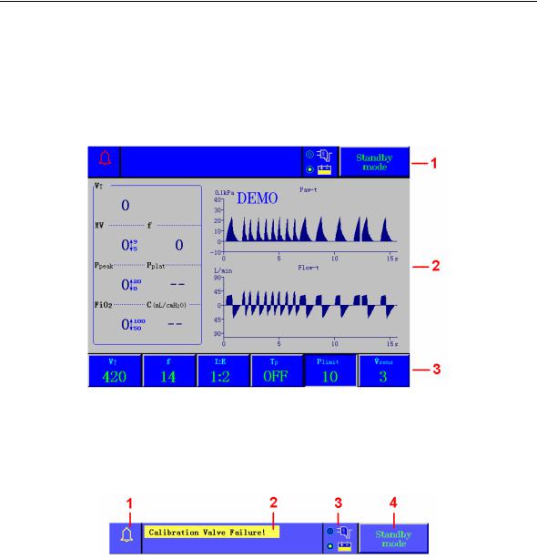
2.4.5Display Screen
The display of the ventilator is a color TFT, which can display the monitoring and setting parameters, waveforms, alarm information as well as displayed on the screen. See Figure 2-9.
The screen has three areas: information area (1), monitoring area (2), and parameter setup area (3).
Figure 2-9 Display Screen
2.4.5.1Information area
Information area lies on the top part of the screen, which is used to display the current status of the ventilator and the patient. The information area contains following components:
Figure 2-10 Information area
1Alarm bell
When alarm appears, the color of alarm bell accords with the background color of the upper prior alarm message; press alarm silence key, “X” dashed line appears on the alarm bell, and 110 seconds counts down. More details refer to section 8.1.
2Alarm messages
Technical alarm and functional alarm supplied by the system, and not more than two alarm messages displayed on the top of the screen. More details refer to section 8.2.
3Power supply
Two kinds of power supply: AC power external and internal battery.
4Ventilation mode
Five ventilation modes: VCV mode, Pressure mode, SIMV mode, Manual mode, and Standby mode.
Turn and press the knob to setup ventilation mode required, and press again to save it.
01/2008 |
2-13 |
ANASTAZJA 7500 User Manual
2.4.5.2Monitoring area
Monitoring area has two parts: Patient parameter and waveform.
Patient parameter is fixedly displayed in the left side of the monitoring area. It includes seven parameters:
VT: |
Tidal volume |
MV: |
Minute volume |
f: |
Respiratory frequency |
Ppeak: |
Peak value of airway pressure |
Pplat: |
Pressure at the end |
of FiO2: |
Oxygen concentration |
|
inspiratory pause time |
|
|
C:compliance
Waveform is displayed in the right side of the monitoring area. It has four types: Flow-t waveform, V-t waveform, Paw-V loop and V-FLOW loop.
More details refer to section 3.5.
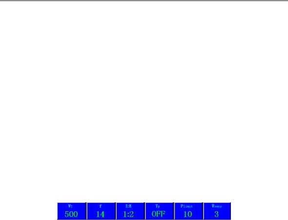
2.4.5.3Parameter setup area
Parameter setup area lies on the bottom part of the screen. It includes:
VT: |
Tidal volume |
f: |
Breaths per minute |
I:E: |
Inspiration to expiration time |
TP: |
Inspiratory pause time |
Plimit: |
Maximum airway pressure limit |
Vsens: |
Triggering flow sensitivity |
|
setting |
|
|
2-14 |
01/2008 |
2 Anesthetic System Control
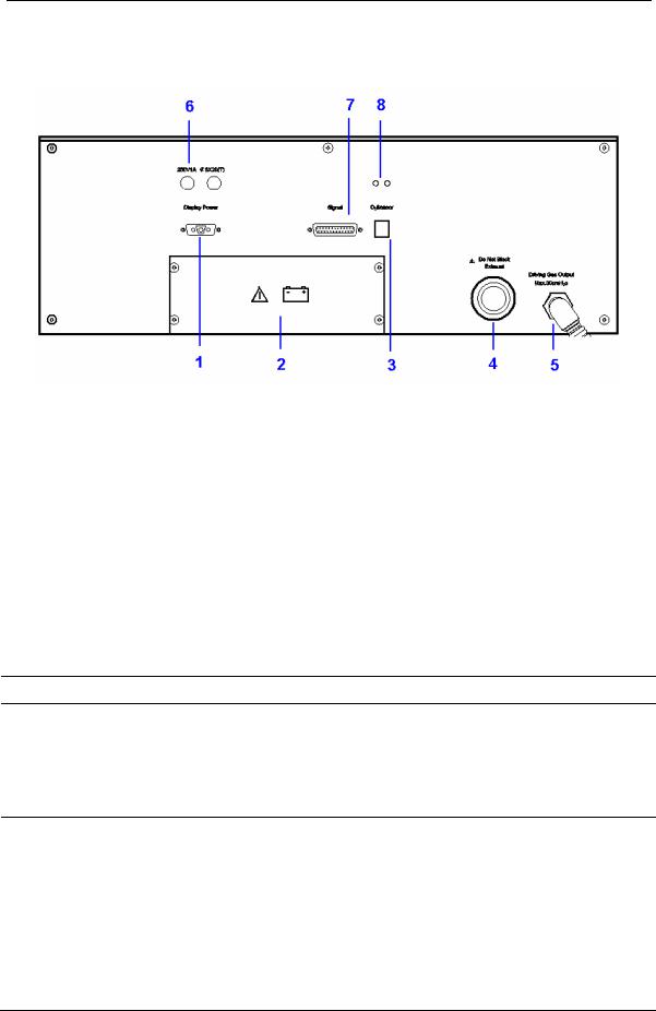
2.4.6Rear Panel
Figure 2-11 Rear Panel
1Display Power interface
2Battery
3 O2 Sensor interface
4Exhaust Port
5 Driven Gas Outlet
6Fuse
7Signal interface
8P&V interface of sampling parallel line
Item |
Description |
Display Power 1&7 interface and
Signal interface
Use display power cable and signal cable to connect relevant interface of rear panel with interfaces on rear of display screen respectively.
Display power interface and signal interface: provide power supply and signal to the display.
2 |
Battery |
Refer to section 7.6 |
|
|
|
|
|
RJ 11 standard interface. |
|
|
Use oxygen sampling line to connect O2 sensor with O2 sensor |
|
|
interface. |
3 |
O2 |
Sensor |
Interface |
Oxygen concentration value measured by O2 sensor is transmitted |
to the ventilator through O2 sensor interface.
If no O2 sensor in the breathing system, the alarm message “No O2 sensor!” will be shown in the display screen.
01/2008 |
2-15 |

ANASTAZJA 7500 User Manual
|
|
Don’t block exhaust port. |
|||
|
|
It is only a outlet of driven gas. Safety valve inside exhaust port may |
|||
4 |
Exhaust Port |
be used |
to limit |
maximum of airway pressure. When airway |
|
pressure exceeding the maximum, the safety valve will open and |
|||||
|
|
||||
|
|
exhaust for protecting airway of patient. |
|||
|
|
The maximum airway pressure is 6 kPa. |
|||
|
|
|
|||
|
|
Size: male 16 mm taper |
|||
|
|
Use thread-tube to connect driven gas outlet with driven gas inlet of |
|||
|
|
bellows. |
|
|
|
5 |
Driven Gas Outlet |
Inspiratory phase: gas from ventilator drives bellows to make fresh |
|||
|
|
gas enter into the airway; |
|||
|
|
Expiratory phase: return gas from the airway drives bellows to make |
|||
|
|
gas from ventilator exhaust through exhaust port. |
|||
|
|
|
|||
6 |
Fuse |
250V 1A 5X20(T), more details refer to section 7.5.3 |
|||
|
|
|
|||
|
|
Connect sampling parallel line to P&V interface, the other end to |
|||
|
|
probe. |
|
|
|
|
|
It provides basis for monitoring and troubleshooting that the real |
|||
|
|
time airway pressure is transmitted to the ventilator. |
|||
8 |
P&V interface |
Parameter monitored such as VT and MV, are calculated by |
|||
|
|
ventilator basing on the flow via the probe. |
|||
|
|
CAUTION |
Ensure sampling line and probe connect |
||
|
|
|
|
right, avoid liquid entering and leakage. |
|
|
|
|
|
||
|
|
—— |
Probe of sampling and sampling parallel line |
||
|
|
Flow of breathing cycle is measured by means of pressure |
|||
|
|
difference. |
|
||
|
|
Avoid water entering into the probe and sampling parallel line in the |
|||
|
|
process of operating, otherwise parameter monitored will be |
|||
|
|
affected. |
|
|
|
|
|
Ensure airtightness of sampling system, if sampling device is aging, |
|||
Accessory relatively |
please replace it. |
|
|||
|
|
Sterilization: cleaning it with sterilizing agent, then swing it |
|||
|
|
mechanically. The formation and preparation of the agent must be |
|||
|
|
done in accordance with the direction given by the manufacturer. |
|||
|
|
—— |
O2 Sensor |
||
|
|
Operation condition: 0.5 to 2.0 Bar. More details refer to section 7.4 |
|||
|
|
|
|
|
|
2-16 |
01/2008 |
 Loading...