


Statement
Beijing Aeonmed Co, Ltd. (Aeonmed for short) holds the copyrights to this manual, which is non-public published, and reserves the rights to keep it as a secure document. Refer to this manual when operating, maintaining and repairing Aeonmed products only. Anyone other than Aeonmed may not make it known to others.
Proprietary materials protected by the copyright law are included in this manual. Any section of it cannot be reproduced, copied, or translated into other languages without any prior written approval from Aeonmed who reserves the copyright.
Everything written in this manual is considered to be correct. Aeonmed is not legally responsible for any mistakes printed within and any damages caused by incorrect installation and operation. Aeonmed does not supply privileges endowed by the patent law to any other parties. Aeonmed is not legally responsible for the results caused by patent law breaking and any rights of the third party violating.
Refer to this manual before any Aeonmed product is used. The manual includes operating procedures which must be performed with cautiously, operations that may result in non-normal working conditions and the dangers which may damage equipment or cause bodily harm. Aeonmed is not responsible for the security, reliability and function of the equipments in case that the dangers, damages and non-normal phenomenon mentioned in this manual happen. Free repairs for these malfunctions will not be provided by Aeonmed.
Aeonmed have the rights to replace any content in this manual without notice.
Manufacturer Responsibility:
Aeonmed is responsible for the security, reliability and function of the equipments when to following conditions are adhered to:
Installation, adjustments, mending and repairs must be performed by individuals authorized by Aeonmed;
Necessary electrical equipment and the working environment must be in accordance with the national standards, professional standards and the requirements listed in this manual;
Equipment must be used as instructed in the operating instructions.
i

Aeon7400A User Manual
CAUTION: This equipment is not for family use.
CAUTION: Malfunctioning equipment may become invalid and cause bodily injury if a set of effective and approving repairing proposals cannot be submitted by the institution which is responsible for using this equipment.
The paid theoretical framework diagram will be supplied according to customer requirements by Aeonmed, plus calibrating method and other information to help the customer, under the assistance of qualified technicians, repair the equipment parts where can be done by customer himself based on the stipulation by Aeonmed.
Warranty:
Manufacturing techniques and materials:
For a period of one year from the date of original delivery, the components and assemblies of this product is warranted to be free from defects manufacturing techniques and materials, provided that the same is properly operated under the conditions of normal use and regular maintenance. The warranty period for other parts is three months. Expendable parts are not included. Aeonmed’s obligation under the above warranties is limited to repairing free of charge.
Free Obligations:
Aeonmed’s obligation under the above warranties does not include the freight and other fees;
Aeonmed is not responsible for any direct, indirect or final product broken and delay which result from improper use, alteration by using the assemblies unratified and maintenance by anyone other than Aeonmed;
This warranty does not apply to the followings: Improper use;
Machines without maintenance or machines broken;
The label of Aeonmed original serial number or mark is removed or replaced;
Other manufacturers’ product.
ii

Contents
Security, reliability and operating condition:
Aeonmed is not responsible for the security, reliability and operating condition of this product in case that:
The assemblies are disassembled, extended and readjusted
This product is not operated correctly in accordance with the manual instruction. The power supply used or operating environment does not follow the requirements in this manual.
Return
Follow the steps in case that the product needs to be returned to Aeonmed:
1. Obtain the rights of return
Contact with the customer service of Aeonmed by informing them the number and type of the product. The number is marked on the surface of the product. Return is unacceptable if the number cannot be identified. Enclose a statement of the number, type and the reason of return as well.
2. Transportation charges
Transportation and insurance charges must be prepaid by the user for transporting the product to Aeonmed for repairing. (Customers charges is added with regard to the products sold to non-Chinese mainland users)
iii

Aeon7400A User Manual
NOTE:
Each Aeonmed product has a serial number, such as
Aeon7400A xx xx xx
Aeon7400A: machine model
the first xx : the year of manufacturing the second xx : the month
the third xx : equipment number
Manufacture: |
Beijing Aeonmed Co., Ltd. |
Address: |
No.4, Hangfeng Road, Fengtai Science Park, Fengtai |
|
District, Beijing, China |
European |
Shanghai International Holding Corp. GmbH (Europe) |
Representative: |
|
Address: |
Eiffestrasse 80, 20537 Hamburg Germany |
P.C.: |
100070 |
Tel: |
+86-10-83681616 |
Fax: |
+86-10-63718989 |
E-mail: |
service@aeonmed.com |
iv
|
|
|
Contents |
|
1 |
Introduction ......................................................................................................... |
1–1 |
||
|
1.1 |
What’s Aeon7400A?...................................................................................... |
1–1 |
|
|
1.1.1 |
Intended Use ......................................................................................... |
1–1 |
|
|
1.2 |
Symbols......................................................................................................... |
1–2 |
|
|
1.3 |
Definition, abbreviation.................................................................................. |
1–4 |
|
2 |
Anesthetic System Control................................................................................ |
2–1 |
||
|
2.1 |
Anesthetic system ......................................................................................... |
2–1 |
|
|
2.2 |
The Breathing system module ...................................................................... |
2–7 |
|
|
2.2.1 |
Bellows assembly Ports......................................................................... |
2–9 |
|
|
2.2.2 |
Ventilating circulation ........................................................................... |
2–10 |
|
|
2.3 |
Vaporizer Control......................................................................................... |
2–10 |
|
|
2.4 |
Ventilator Control......................................................................................... |
2–10 |
|
|
2.4.1 |
Front Panel .......................................................................................... |
2–11 |
|
|
2.4.2 |
Rear Panel........................................................................................... |
2–16 |
|
3 |
Operating Guide.................................................................................................. |
3–1 |
||
|
3.1 |
Starting System ............................................................................................. |
3–1 |
|
|
3.1.1 |
Alarm Limit Set ...................................................................................... |
3–1 |
|
|
3.1.2 |
Ventilator Control Set............................................................................. |
3–2 |
|
|
3.2 |
Starting IPPV Ventilation ............................................................................... |
3–3 |
|
|
3.3 |
Starting Manual Ventilation............................................................................ |
3–4 |
|
4 |
Preoperative Checkout....................................................................................... |
4–1 |
||
|
4.1 |
Preoperative Checkout procedures............................................................... |
4–1 |
|
|
4.1.1 |
System Checkout................................................................................... |
4–3 |
|
|
4.1.2 |
Mains failure alarm test.......................................................................... |
4–4 |
|
|
4.2 |
Testing gas supply pipeline and gas cylinder................................................ |
4–4 |
|
|
4.3 |
Monitoring Flow Control ................................................................................ |
4–7 |
|
|
4.4 |
Installing and testing of vaporizer................................................................ |
4–10 |
|
|
4.5 |
Alarm testing ............................................................................................... |
4–10 |
|
|
4.6 |
Testing the Breathing System ..................................................................... |
4–10 |
|
|
4.6.1 |
Checking Oxygen flush button............................................................. |
4–11 |
|
|
4.6.2 |
Testing Breathing System.................................................................... |
4–11 |
|
|
4.6.3 |
Testing APL Valve ................................................................................ |
4–11 |
|
|
4.7 |
Testing Ventilator ......................................................................................... |
4–12 |
|
v

Aeon7400A User Manual
5 Installing and Connecting .................................................................................. |
5–1 |
||
5.1 |
Installing Product ........................................................................................... |
5–3 |
|
5.2 |
Installing Absorber ......................................................................................... |
5–5 |
|
5.2.1 |
When to replace absorbent.................................................................... |
5–6 |
|
5.2.2 |
Disassembling Absorber ........................................................................ |
5–6 |
|
5.2.3 |
Filling Absorbent .................................................................................... |
5–7 |
|
5.3 |
Connecting tubes and lines ........................................................................... |
5–7 |
|
5.4 |
Connecting Gas and Electricity ................................................................... |
5–11 |
|
5.4.1 |
AC inlet ............................................................................................... |
5–12 |
|
5.4.2 |
Auxiliary mains socket outlet .............................................................. |
5–13 |
|
5.4.3 |
Pipeline gas supply inlet ..................................................................... |
5–14 |
|
5.4.4 |
Cylinder gas supply inlet..................................................................... |
5–14 |
|
5.5 |
Install gas cylinder (Test high pressure leak) ............................................. |
5–15 |
|
5.6 |
Connect to AGSS ....................................................................................... |
5–17 |
|
6 Cleaning and Disinfecting.................................................................................. |
6–1 |
||
6.1 |
Cleaning and disinfection of pre-use first ...................................................... |
6–2 |
|
6.2 |
Cleanable Breathing System Components ................................................... |
6–3 |
|
6.3 |
Absorber ........................................................................................................ |
6–4 |
|
6.3.1 |
Auto cleaning with agent or disinfectant ................................................ |
6–4 |
|
6.3.2 |
Manual cleaning..................................................................................... |
6–4 |
|
6.3.3 |
Advanced Sterilizing .............................................................................. |
6–4 |
|
6.4 |
Absorber assembly........................................................................................ |
6–5 |
|
6.5 |
The Bellows Assembly................................................................................... |
6–5 |
|
6.5.1 |
Disassembling........................................................................................ |
6–6 |
|
6.5.2 |
Testing Function..................................................................................... |
6–9 |
|
6.5.3 |
Bellows Assembly lists........................................................................ |
6–12 |
|
6.5.4 |
Cleaning and Disinfecting ................................................................... |
6–13 |
|
6.5.5 |
Regular Maintenance.......................................................................... |
6–16 |
|
7 User Maintenance ............................................................................................... |
7–1 |
||
7.1 |
Repair Policy ................................................................................................. |
7–2 |
|
7.2 |
Maintaining Outline and Schedule................................................................. |
7–2 |
|
7.2.1 |
User maintenance.................................................................................. |
7–3 |
|
7.2.2 |
Permissive Repairing............................................................................. |
7–3 |
|
7.2.3 |
Useful life estimation.............................................................................. |
7–4 |
|
7.3 |
Maintaining the Breathing System................................................................. |
7–4 |
|
vi

Contents
|
7.4 |
Maintaining flow sensor................................................................................. |
7–4 |
|
|
7.5 |
Replacing fuses............................................................................................. |
7–5 |
|
|
7.5.1 |
Replacing fuse of mains supply............................................................. |
7–5 |
|
|
7.5.2 |
Replacing fuse of auxiliary mains socket outlets................................... |
7–6 |
|
|
7.5.3 |
Replacing fuse of the ventilator ............................................................. |
7–6 |
|
8 |
Alarm and Troubleshooting ............................................................................... |
8–1 |
||
|
8.1 |
About alarm ................................................................................................... |
8–1 |
|
|
8.2 |
Troubleshooting............................................................................................. |
8–2 |
|
|
8.2.1 |
Anesthesia machine .............................................................................. |
8–2 |
|
|
8.2.2 |
Anesthetic Ventilator .............................................................................. |
8–3 |
|
9 |
Ordering information.......................................................................................... |
9–1 |
||
|
9.1 |
Key components............................................................................................ |
9–1 |
|
|
9.2 |
Bellows Parts List .......................................................................................... |
9–2 |
|
|
9.3 |
Accessories ................................................................................................... |
9–3 |
|
|
9.4 |
Expendable parts........................................................................................... |
9–4 |
|
10 |
Specifications and Operation Theory ......................................................... |
10-1 |
||
|
10.1 |
Schematic diagram...................................................................................... |
10-1 |
|
|
10.2 |
System technical specification .................................................................... |
10-3 |
|
|
10.2.1 |
Drive..................................................................................................... |
10-3 |
|
|
10.2.2 |
Flow ..................................................................................................... |
10-4 |
|
|
10.2.3 |
Classification........................................................................................ |
10-5 |
|
|
10.3 |
Power supply............................................................................................... |
10-5 |
|
|
10.4 |
Electromagnetic Compatibility..................................................................... |
10-6 |
|
|
10.5 |
Physical specification .................................................................................. |
10-8 |
|
|
10.6 |
Environment requirements .......................................................................... |
10-8 |
|
|
10.7 |
Breathing system technical specifications................................................... |
10-9 |
|
|
10.7.1 |
Performance of ventilator................................................................... |
10-10 |
|
|
10.7.2 |
Setting ventilation mode .................................................................... |
10-10 |
|
|
10.7.3 |
Setting ventilating parameters ........................................................... |
10-10 |
|
|
10.7.4 |
Gas dynamics performance................................................................ |
10-11 |
|
|
10.7.5 |
Setting alarm parameters ................................................................... |
10-11 |
|
|
10.7.6 |
Volume and pressure.......................................................................... |
10-11 |
|
|
10.7.7 |
Monitoring performance..................................................................... |
10-12 |
|
vii

Aeon7400A User Manual
viii
1 Introduction
1.1What’s Aeon7400A?
Aeon7400A is a compact and integrated anesthesia transmitting system. The breathing machine not only provides patients in operation with IPPV ventilation, but also monitors and displays the patient’s various parameters. The ventilator used in the system is controlled by a microprocessor. Aeon7400A is intended for use in the operating room and emergency department of hospital.
Not all the optional functions available may be included in the manual. It is also possible to add other equipment to the top or middle of this system for added functions. For more information with respect to the existing product, please feel free to contact the local representatives.
 WARNING: The user of Aeon7400A must be professional and trained.
 WARNING: Aeon7400A is unsuitable for use in a magnetic resonance imaging (MRI) environment.
1.1.1Intended Use
Aeon7400A is applicable for patients of over 25Kg with standard configuration.
 WARNING: Aeon7400A is not to be used for infant anaesthesia.
1–1
Aeon7400A User Manual
1.2Symbols
 Warnings and
  Cautions indicate all the possible dangers in case of violation of the stipulations in this manual. Refer to and follow them.
 WARNING: indicates potential hazards to operators or patients
  CAUTION: indicates potential damage to equipment
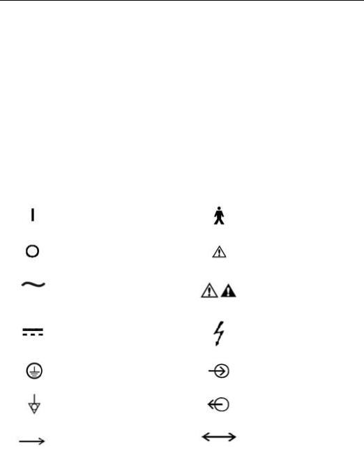
Instead of illustrations, other symbols may also be utilized. Not all of them may necessarily appear in the equipment and manual. The symbols include:
ON Power |
|
|
Type B equipment |
|
|
OFF Power |
|
Warning or Caution, ISO |
|||
|
7000-0434 |
|
|
||
|
|
|
|
|
|
Alternating Current |
|
NOTE: refer |
to |
the |
|
|
manual, IEC601-1 |
|
|||
|
|
|
|
||
Direct Current |
|
|
Dangerous Voltage |
|
|
Protectively earth |
|
Input |
|
|
|
Equipotential |
|
|
Output |
|
|
Movement |
in |
one |
Movement |
in |
two |
direction |
|
|
directions |
|
|
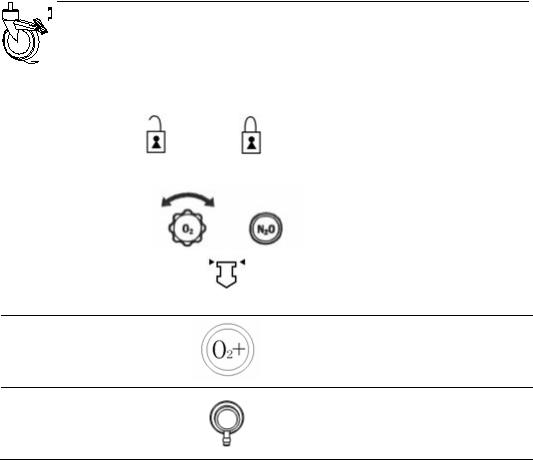
1–2
1 Introduction
Lock
Unlock
Inspiration flow
O2+ Oxygen flush
Alarm Silence
Ventilator operate
Directions of Drain Valve
CE Representative
Date of manufacture
Address of manufacture
Expiration flow
SN Serial Number
View the reading on the top of float
Bag operate
Battery
The system, with this label under the stipulations in the operating manual, complies with the requirements related from 93/42/EEC.
1–3

Aeon7400A User Manual
1.3Definition, abbreviation
Not all of the following definition or abbreviation may necessarily appear in the equipment and manual.
AC100 |
Code name of Circle Absorber with rotation handle |
|
|
AC110 |
Code name of Circle Absorber with pulling handle |
|
|
AGSS |
Anesthetic gas scavenging transfer & receiving system |
|
|
APL |
Adjustable Pressure Limit |
|
|
BA100 |
Code name of bellows for adult use |
|
|
BA150 |
Code name of bellows for pediatric use |
|
|
C |
Compliance |
|
|
CGO |
Common Gas Outlet |
|
|
f |
Breath frequency |
|
|
FiO2 |
Oxygen concentration |
Flow-t |
Flow-time waveform |
|
|
I:E |
Inspiration to expiration time |
|
|
IPPV |
Intermittent positive pressure ventilation |
|
|
Manual |
Manual ventilation |
|
|
MV |
Minute volume |
|
|
Paw |
Pressure of airway |
|
|
Ppeak |
Peak pressure |
|
|
Pplat |
Plat pressure |
|
|
Paw-t |
Pressure-time waveform |
|
|
V-t |
Tidal volume-time waveform |
|
|
F-t |
Flow-Time waveform |
|
|
VT |
Tidal volume |
|
|
VTI |
Inspiratory tidal volume |
|
|
VTE |
Expiratory tidal volume |
|
|
1–4
2 Anesthetic System Control
2.1Anesthetic system
 CAUTION: The anesthetic system is intended to be used with the following monitoring devices, alarm systems, and protection devices:
--pressure measuring in accordance with 8.1 of ISO 8835-2;
--pressure limitation device in accordance with 51.101.1 of IEC60601-2-13;
--exhaled volume monitor in accordance with 51.101.4 of IEC60601-2-13;
--breathing system integrity alarm system in accordance with 51.101.5 of IEC60601-2-13;
--continuing pressure alarm in accordance with 51.101.6 of IEC60601-2-13;
--O2 monitor in accordance with ISO 7767.
 WARNING: To avoid explosion hazards, flammable anesthetic agents such as ether and cyclopropane shall not be used in this anesthetic workstation. Only anesthetic agents which comply with the requirements for non-flammable anesthetic agents as specified in this manual.
Halothane, Desflurane, Sevoflurane, Enflurane, and Isoflurane have been found to be non-flammable agents.
 WARNING: Independent means of ventilation (e.g. a self-inflating manually powered resuscitator with mask) should be available whenever the anesthetic system is in use.
 WARNING: Do not use antistatic or electrically-conductive breathing tubes and mask.
 WARNING: Leakage and douse of liquid, such as anesthetic agent, bring on dangerous states or malfunctions inside device.
2–1
Aeon7400A User Manual
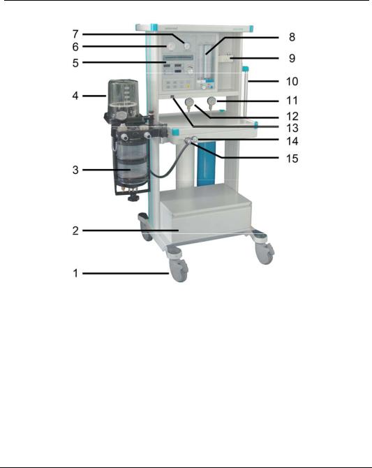
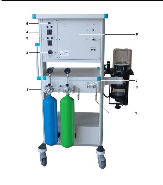
Figure 2-1 Aeon7400A front view (European version)
Legend:
1 |
Castor |
2 |
Drawer |
|
|
|
|
3 |
AC100 |
4 |
BA100 |
|
|
|
|
5 |
MV200B |
6 |
O2 pipeline pressure gauge |
7 |
N2O pipeline pressure gauge |
8 |
Flowmeters |
9 |
Manifold valve |
10 |
Handle |
|
|
|
|
11 |
N2O cylinder pressure gauge* |
12 |
O2 cylinder pressure gauge* |
13 |
Power switch |
14 |
Oxygen Flush |
|
|
|
|
15 |
CGO |
|
|
*Cylinder pressure gauges are available when Aeon7400A equipped with gas cylinders.
2–2
2 Anesthetic System Control
Figure 2-1 each control function on the front view of Aeon 7400A
|
Item |
Diagram |
Description |
|
|
|
|
1 |
Castor with |
|
Push down to lock, and pull up |
break |
|
to unlock. |
|
|
|
||
|
|
|
|
|
|
|
Turn the knob counterclockwise |
|
|
|
to increase the flow; turn |
8 |
Flow Control |
|
clockwise to decrease the flow. |
|
|
|
Read top of float when the |
|
|
|
flowmeter is being read. |
14Oxygen Flush
15CGO
Press Oxygen Flush button to supply O2 to the breathing system with high flow rate
Connects the anesthesia machine to the breathing system
2–3
Aeon7400A User Manual
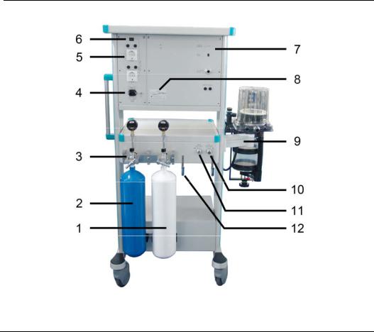
Figure 2-2 Aeon 7400A back view (European version)
Legend:
1 |
O2 cylinder (optional) |
2 |
N2O cylinder (optional) |
3 |
Yoke system (optional) |
4 |
Power socket |
|
|
|
|
5 |
AMSO |
6 |
Auxiliary mains switch |
|
|
|
|
7 |
Rear panel of MV200B |
8 |
Nameplate |
|
|
|
|
9 |
Support arm |
10 |
O2 pipeline inlet |
|
|
|
|
11 |
N2O pipeline inlet |
12 |
Hook |
|
|
|
|
2–4

2 Anesthetic System Control
Figure 2-3 Aeon7400A front view (USA version)
Legend:
1 |
Castor |
2 |
Drawer |
|
|
|
|
3 |
AC100 |
4 |
BA100 |
|
|
|
|
5 |
MV200B |
6 |
N2O pipeline pressure gauge |
7 |
O2 pipeline pressure gauge |
8 |
Flowmeters |
9 |
Manifold valve |
10 |
Handle |
|
|
|
|
11 |
N2O cylinder pressure gauge* |
12 |
O2 cylinder pressure gauge* |
13 |
Power switch |
14 |
Oxygen Flush |
|
|
|
|
15 |
CGO |
16 |
N2O cylinder (optional) |
17 |
O2 cylinder (optional) |
|
|
*Cylinder pressure gauges are available when Aeon7400A equipped with gas cylinders.
2–5
Aeon7400A User Manual
Figure 2-4 Aeon 7400A back view (USA version)
Legend:
1 |
Yoke system (optional) |
2 |
Power socket |
|
|
|
|
3 |
Fuse |
4 |
AMSO |
|
|
|
|
5 |
Auxiliary mains switch |
6 |
Rear panel of MV200B |
|
|
|
|
7 |
N2O pipeline inlet |
8 |
O2 pipeline inlet |
|
|
|
|
9 |
Hook |
|
|
|
|
|
|
2–6
2 Anesthetic System Control
2.2The Breathing system module
 CAUTION: Any adult anesthetic ventilator system used together with the anesthetic gas supply system must be in accordance with ISO 8835-2.
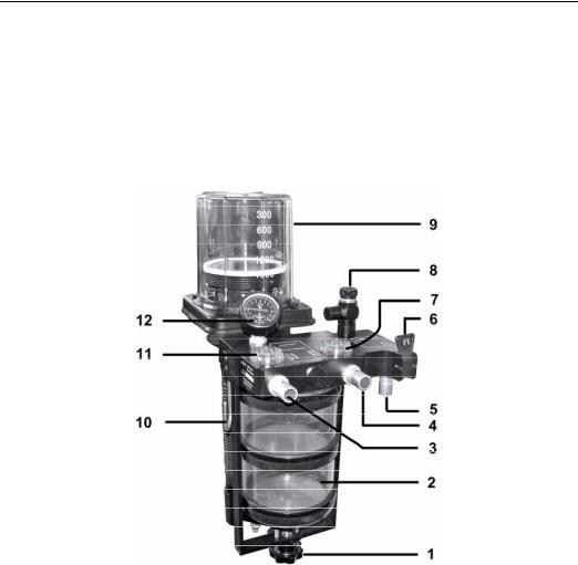
Figure 2-5 Breathing system module
Legend:
1 |
Absorber mount release handle |
2 |
Absorber |
|
|
|
(Carbon dioxide absorbent) |
|
|
|
|
3 |
Expiratory Port |
4 |
Inspiratory Port |
|
(Patient circuit connector) |
|
(Patient circuit connector) |
|
|
|
|
5 |
Manual reservoir bag port |
6 |
Bag / Ventilator switch |
|
|
|
|
7 |
Inspiratory valve |
8 |
APL valve |
|
|
|
|
9 |
Bellows assembly (IPPV ventilation) |
10 |
Hook |
|
|
|
|
11 |
Expiratory valve |
12 |
Airway pressure gauge |
|
|
|
|
2–7
Aeon7400A User Manual
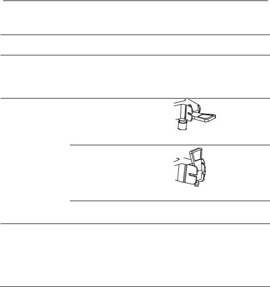
Figure 2-5 the breathing system components function control
Item |
Description |
1Absorber mount release
Two soda lime canisters are applied with a volume of 1500mL for each so that it can be continuously used for 6 to 8 hours at full load. The water from the reaction is drained via the water collector underneath.
IPPV ventilation “off”:
(gas into reservoir bag)
6 |
Bag / Ventilator |
|
switch |
||
|
IPPV ventilation “on”:
(gas into bellows)
Select manual ventilation (reservoir bag) or IPPV ventilation (ventilator).
Adjust the pressure limit of the breathing system during the manual ventilation process. The readings are approximate.
8 APL valve The colors represent different pressure zones. Green represents safety zone; yellow represents transition zone; red represents high pressure zone. Adjusting ranges between 0.19-6kPa.
2–8
2 Anesthetic System Control
2.2.1Bellows assembly Ports
Figure 2-6 Ports of bellows assembly
1 Breathing system connector 2 Exhaust gas port 3 Driving gas connector 4 Adapter
 WARNING: Never connect exhaust gas port with sub-atmospheric system directly. Or else leakage of breathing system generates.
The adapter can be used to connect the waste gas scavenging system to the bellows assembly if the standard pipeline is used in the waste gas scavenging system.
2–9
Aeon7400A User Manual
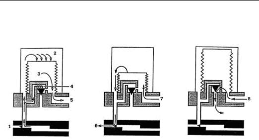
2.2.2Ventilating circulation
Inhalation |
primary |
Exhalation |
primary |
Exhalation end phase: |
||
phase: |
|
phase: |
|
8 Excess gas of patient |
||
|
|
|
|
|
|
|
1 |
Exhalation valve |
6 |
Driving gas |
|
circuit |
|
2 |
Driving gas |
|
7 |
From patient circuit |
|
|
3 |
Gas of patient circuit |
|
|
|
|
|
4 |
Pressure-relief valve |
|
|
|
|
|
5 To patient circuit
2.3Vaporizer Control
Refer to operating and maintenance manual of vaporizer for more details.
 WARNING: Anesthetic vapor delivery device used with anesthetic system must be in accordance with ISO 8835-4.
2.4Ventilator Control
 CAUTION: Anesthetic ventilator accords with ISO 8835-5.
2–10
2 Anesthetic System Control
 CAUTION: Monitoring conditions of this system: Ambient temperature: 29 ;
Air temperature: 30 ;Air humidity: 30%; Gas component:
Oxygen.
 CAUTION: If the temperature of sensor is lower than dew point of breathing gas, vapor may coagulate on the surface of sensor, and oxygen concentration monitored may be lower than practice value.
 CAUTION: If the temperature of sensor is lower than dew point of breathing gas, vapor may coagulate on the surface of sensor, and tidal volume monitored may be lower than practice value.
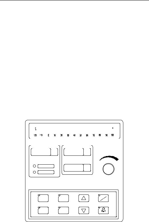
2.4.1Front Panel
Front panel consists of display screen, keys, indicators, and a knob.
|
|
|
Airway pressure |
|
X0.1kPa |
|||||||||||||||||
|
|
|
|
|
|
|
|
|
|
|
|
|
|
|
|
|
|
|
|
|
|
|
|
|
|
|
|
|
|
|
|
|
|
|
|
|
|
|
|
|
|
|
|
|
|
|
|
|
|
|
|
|
|
|
|
|
|
|
|
|
|
|
|
|
|
|
|
|
|
|
|
|
|
|
|
|
|
|
|
|
|
|
|
|
|
|
|
|
|
|
|
|
|
|
|
|
|
|
|
|
|
|
|
|
|
|
|
|
|
|
|
|
|
|
|
|
|
|
|
|
|
|
|
|
|
|
|
|
|
|
|
|
|
|
|
|
|
|
|
|
|
|
|
|
|
|
|
|
|
|
|
|
|
|
|
|
|
|
|
|
|
|
|
|
|
|
|
|
|
|
|
|
|
|
|
|
|
|
|
|
|
|
|
|
|
|
|
|
|
|
|
|
|
|
|
|
|
|
|
|
|
|
|
|
|
|
mL |
bpm |
VT |
f |
High Paw |
I:E |
|
|
Low Paw |
|
Tidal volume
0.1kPa |
BPM |
MANUAL |
HIGH PRESSURE |
f |
IPPV |
0.1kPa |
I:E |
LOW PRESSURE |
2min |
|
Figure 2-7 Front Panel
2–11
Aeon7400A User Manual
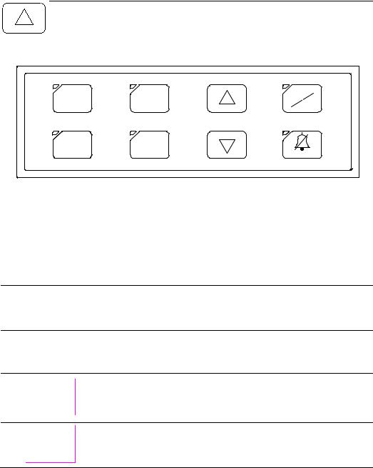
2.4.1.1Control part
0.1kPa |
BPM |
MANUAL |
|
||
HIGH PRESSURE |
f |
IPPV |
0.1kPa |
I:E |
|
LOW PRESSURE |
|
2min |
|
|
Figure 2-8 |
Control Part |
|
|
Items |
Function |
|
|
High airway pressure limit setting key.
Low airway pressure limit setting key.
Respiratory frequency setting key ranging from six to sixty bpm.
Inspiration and respiratory ratio setting key, totally six positions:
1:4, 1:3, 1:2, 2:3, 1:1, 2:1.
Increase each parameter’s value on screen. (Increasing key)
2–12
2 Anesthetic System Control
Decrease each parameter’s value on screen. (Decreasing key)
Manual/IPPV change switch
Eliminate alarm. When alarming, press the key to eliminate alarm.
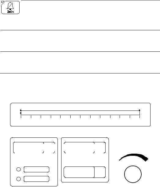
2.4.1.2Display Screen
Airway pressure |
|
|
|
|
|
|
|
X0.1kPa |
||||
-20 |
-10 |
O |
10 |
20 |
30 |
40 |
50 |
60 |
70 |
80 |
90 |
100 |
|
mL |
|
|
|
bpm |
|
|
VT |
|
|
|
f |
|
|
|
|
|
|
|
|
High Paw |
I:E |
|
|
Low Paw |
|
Tidal volume
Figure 2-9 Display Screen
2–13

Aeon7400A User Manual
Display symbol’s |
Function |
|
implication |
||
|
||
|
|
|
|
Airway pressure display |
|
Airway pressure |
Reflect the airway pressure change when patients |
|
|
respiration. |
|
|
|
|
|
Display the tidal volume value. |
|
|
|
|
|
Display Respiratory frequency. |
|
|
|
|
|
Display Inspiration and respiratory ratio. |
|
|
|
|
|
Alarm indicator for High Paw. |
|
|
|
|
|
Alarm indicator for Low Paw. |
|
|
|
2–14
2 Anesthetic System Control
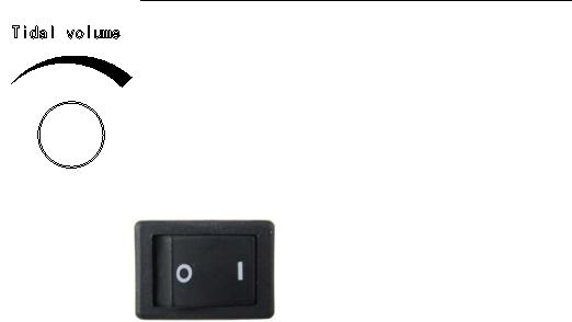
2.4.1.3Others
The nether picture shows the drawings of the power switch and the tidal volume control knob.
|
Figure 2-10 Others Part |
|
|
|
|
Items |
Function |
|
|
|
|
Power switch |
“I” is the denotation of "switch on", and the “O” is the denotation of |
|
|
"switch off". |
|
|
|
|
Tidal Volume |
Using for inspiratory VT. Turn the knob clockwise to enlarge the VT. |
|
control knob |
||
|
||
|
|
2–15
Aeon7400A User Manual
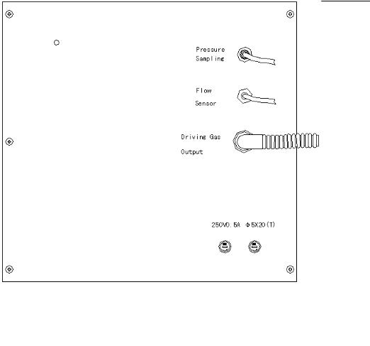
2.4.2Rear Panel
|
Figure 2-11 Rear Panel |
Legend: |
|
|
|
Items |
Function |
|
|
Pressure Sampling: |
Gather Paw by pressure sampling port and then |
|
transfer them to the system at real time to offer gist for |
|
system's monitor and trouble judgment. |
|
|
Flow Sensor: |
The monitor of VT is gained from the flow, which was |
|
gathered by the Flow Sensor. |
|
|
Driving Gas Output: |
Offer driving gas to drive bellows. |
|
|
Fuse: |
Please refer to section 10.3 |
|
|
2–16

3 Operating Guide
3.1Starting System
Step 1: Connect power supply
Plug the power cord into AC power outlet.
Step 2: Power-on
Set power switch to ON (“I”).
 WARNING If any unusual malfunction appears, change bag / ventilator switch to manual mode, stop mechanical ventilating.
3.1.1Alarm Limit Set
Step 1
Press , the indicator light on the top left corner will be lighten and this shows the upper limit of Paw can be reset now.
Step 2
Pressing the keys of or , the position of the red light on the right side of the Paw display tube will be changed which shows the upper limit of the Paw has been reset.
Reset of the lower limit of Paw is the same.
3–1

Aeon7400A User Manual
3.1.2Ventilator Control Set
Press , the indicator light on the top left corner will be lighten and then press or to reset the RATE.
Press , the indicator light on the top left corner will be lighten and then press or to reset the RATIO.
3–2
 Loading...