

Page 1
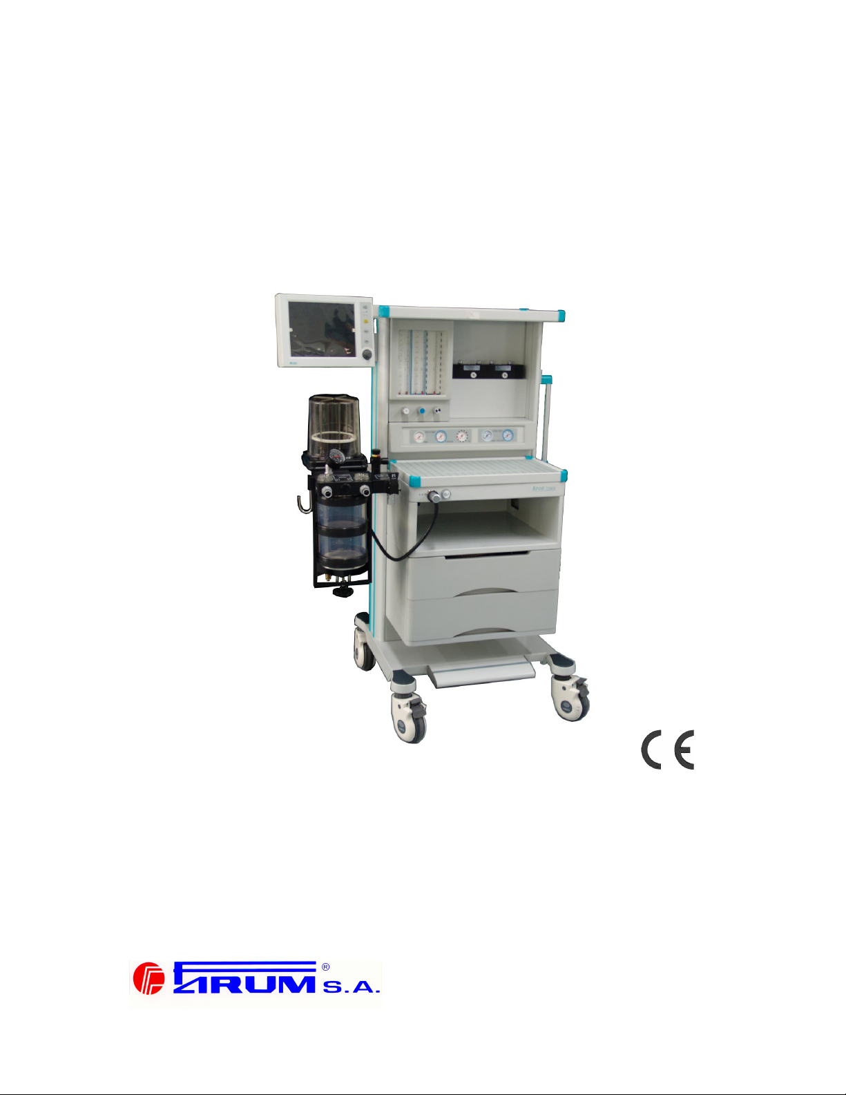
Anesthetic Apparatus
Typ Anastazja 7500
0297
User’s Manual
01/2008
14.01.2008
FARUM S.A.
Adres: 74 Jagiellońska street, 03-301 Warszawa,Poland
Heandquarter (0-22) 811 14 11 Sales Department (0-22) 811 06 79
Fax. (0-22) 811 40 59 Tel./Fax. (0-22) 811 19 22
www.farum.com.pl
Page 2

ANASTAZJA 7500 User Manual
User Responsibility
This product will perform in conformity with the description contained in the operating manual
and accompanying labels and /or inserts, when assembled, operated, maintained and repaired
in accordance with the instructions provided. This product must be checked periodically. Do not
use product if defective. Replace all broken, missing, worn, distorted or contaminated parts. If
repair or replacement becomes necessary, a telephone call or written request for service
advice should be made to the nearest Aeonmed customer service center. This product or any
of its parts must be repaired in accordance with the written instructions provided by Aeonmed
and by Aeonmed trained personnel. The product must not be altered without the prior written
approval of Aeonmed. The user of this product shall assume the full responsibility for any
malfunction resulting from improper use, faulty maintenance, improper repair, damage or
alteration by anyone other than Aeonmed personnel.
NOTE:
Each FARUM S.A. product has a serial number, such as
Anastazja7500 xxxx-xxxxx
ANASTAZJA 7500: machine model
the first xxxx : the year of manufacturing
the second xx : the month
the third xxx : equipment number
2 01/2008
Page 3

Statement
FARUM S.A. holds the copyrights to this manual, which is non-public published, and reserves
the rights to keep it as a secure document. Refer to this manual when operating, maintaining
and repairing FARUM S.A. products only. Anyone other than FARUM S.A. may not make it
known to others.
Proprietary materials protected by the copyright law are included in this manual. Any section of
it cannot be reproduced, copied, or translated into other languages without any prior written
approval from FARUM S.A. who reserves the copyright.
Everything written in this manual is considered to be correct. FARUM S.A. is not legally
responsible for any mistakes printed within and any damages caused by incorrect installation
and operation. FARUM S.A. does not supply privileges endowed by the patent law to any other
parties. FARUM S.A. is not legally responsible for the results caused by patent law breaking
and any rights of the third party violating.
Refer to this manual before any FARUM S.A. product is used. The manual includes operating
procedures which must be performed with cautiously, operations that may result in non-normal
working conditions and the dangers which may damage equipment or cause bodily harm.
FARUM S.A. is not responsible for the security, reliability and function of the equipments in
case that the dangers, damages and non-normal phenomenon mentioned in this manual
happen. Free repairs for these malfunctions will not be provided by FARUM S.A..
FARUM S.A. have the rights to replace any content in this manual without notice.
Manufacturer Responsibility:
FARUM S.A. is responsible for the security, reliability and function of the equipments when to
following conditions are adhered to:
Installation, adjustments, mending and repairs must be performed by individuals
authorized by FARUM S.A.;
Necessary electrical equipment and the working environment must be in accordance with
the national standards, professional standards and the requirements listed in this manual;
Equipment must be used as instructed in the operating instructions.
CAUTION: This equipment is not for family use.
CAUTION: Malfunctioning equipment may become invalid and cause bodily injury if a
set of effective and approving repairing proposals cannot be submitted by the institution
which is responsible for using this equipment.
The paid theoretical framework diagram will be supplied according to customer
requirements by FARUM S.A., plus calibrating method and other information to help the
customer, under the assistance of qualified technicians, repair the equipment parts where can
be done by customer himself based on the stipulation by FARUM S.A..
01/2008 1
Page 4

ANASTAZJA 7500 User Manual
Warranty:
Manufacturing techniques and materials:
For a period of three months from the date of original delivery, the components and assemblies
of this product is warranted to be free from defects manufacturing techniques and materials,
provided that the same is properly operated under the conditions of normal use and regular
maintenance. The warranty period for other parts is three years. Expendable parts are not
included. FARUM S.A. obligation under the above warranties is limited to repairing free of
charge.
Free Obligations:
FARUM S.A. obligation under the above warranties does not include the freight and
other fees;
FARUM S.A. is not responsible for any direct, indirect or final product broken and
delay which result from improper use, alteration by using the assemblies unratified
and maintenance by anyone other than FARUM S.A.;
This warranty does not apply to the followings:
Improper use
Machines without maintenance or machines broken
The label of FARUM S.A. original serial number or mark is removed or replaced
Other manufacturers’ product
Security, reliability and operating condition:
FARUM S.A. is not responsible for the security, reliability and operating condition of this product
in case that:
The assemblies are disassembled, extended and readjusted
This product is not operated correctly in accordance with the manual instruction. The
power supply used or operating environment does not follow the requirements in this
manual.
2 01/2008
Page 5

Return
Follow the steps in case that the product needs to be returned to FARUM S.A.:
1. Obtain the rights of return
Contact with the customer service of FARUM S.A. by informing them the number and type
of the product. The number is marked on the surface of the product. Return is unacceptable if
the number cannot be identified. Enclose a statement of the number, type and the reason of
return as well.
2. Transportation charges
Transportation and insurance charges must be prepaid by the user for transporting the
product to FARUM S.A. for repairing. (Customers charges is added with regard to the products
sold to non-Chinese mainland users)
01/2008 3
Page 6

Page 7

Contents
STATEMENT ............................................................................................................................... 1
1 INTRODUCTION............................................................................................................... 1-1
1.1 WHAT’S ANASTAZJA 7500?..............................................................................................1-1
1.1.1 Range for used ......................................................................................................... 1-1
1.2 SYMBOLS USED IN THE MANUAL AND IN THE EQUIPMENT ......................................................1-3
2 ANESTHETIC SYSTEM CONTROL ................................................................................ 2-1
2.1 ANESTHETIC SYSTEM.......................................................................................................... 2-1
2.2 THE BREATHING SYSTEM MODULE ....................................................................................... 2-5
2.2.1 Absorber cycle .......................................................................................................... 2-7
2.2.2 Bellows Assembly................................................................................................... 2-10
2.3 VAPORIZER CONTROL ....................................................................................................... 2-11
2.4 VENTILATOR CONTROL...................................................................................................... 2-11
2.4.1 Front Panel ............................................................................................................. 2-11
2.4.2 Keys........................................................................................................................ 2-12
2.4.3 Indicators ................................................................................................................ 2-12
2.4.4 Knob ....................................................................................................................... 2-12
2.4.5 Display Screen........................................................................................................2-13
2.4.6 Rear Panel.............................................................................................................. 2-15
2.5 MENU .............................................................................................................................. 2-17
2.5.1 Operating Guide ..................................................................................................... 2-17
2.5.2 Menu diagram......................................................................................................... 2-20
3 OPERATING GUIDE......................................................................................................... 3-1
3.1 STARTING SYSTEM ............................................................................................................. 3-1
3.1.1 Alarm Limit Set ......................................................................................................... 3-3
3.1.2 Restore Default Set .................................................................................................. 3-6
3.1.3 Ventilation Mode Set................................................................................................. 3-9
3.1.4 Ventilator Control Set..............................................................................................3-10
3.2 STARTING AUTO VENTILATION ........................................................................................... 3-11
3.3 SHUTTING OFF AUTO VENTILATION.................................................................................... 3-12
3.4 ALARM ............................................................................................................................. 3-13
3.4.1 Alarm tone .............................................................................................................. 3-13
3.4.2 Alarm Silence..........................................................................................................3-13
3.5 WAVEFORM ...................................................................................................................... 3-14
4 PREOPERATIVE CHECKOUT......................................................................................... 4-1
4.1 ANASTAZJA7500 PREOPERATIVE CHECKOUT PROCEDURES..................................................4-1
4.1.1 System Checkout ..................................................................................................... 4-2
4.1.2 Mains failure alarm test ............................................................................................4-2
4.2 TESTING THE GAS SUPPLY PIPELINE AND THE GAS CYLINDER ................................................. 4-3
4.3 MONITORING FLOW CONTROL............................................................................................. 4-5
4.3.1 Monitoring without oxygen........................................................................................ 4-5
4.3.2 Monitoring with Oxygen ............................................................................................ 4-7
4.4 INSTALLING AND TESTING OF VAPORIZER .............................................................................. 4-9
4.4.1 Installation................................................................................................................. 4-9
4.4.2 Testing Vaporizer Back Pressure ............................................................................. 4-9
4.5 TESTING ALARM................................................................................................................ 4-10
4.6 TESTING THE BREATHING SYSTEM.....................................................................................4-12
4.6.1 Checking Oxygen flush Switch ............................................................................... 4-12
4.6.2 Testing Breathing System....................................................................................... 4-12
4.6.3 Testing APL Valve................................................................................................... 4-12
4.7 TESTING VENTILATOR .......................................................................................................4-13
01/2008 i
Page 8

ANASTAZJA 7500 User Manual
5 INSTALLING AND CONNECTING................................................................................... 5-1
5.1 INSTALLING PRODUCT .........................................................................................................5-2
5.1.1 Shelf..........................................................................................................................5-2
5.1.2 Breathing circuit limb ................................................................................................ 5-2
5.1.3 Absorber cycle ..........................................................................................................5-2
5.1.4 The bellows Assembly base ..................................................................................... 5-2
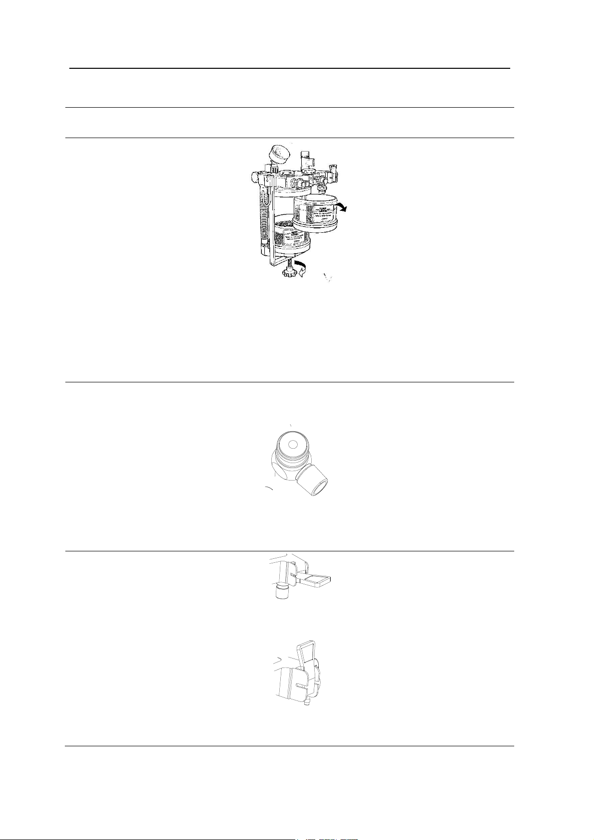
5.2 INSTALLING ABSORBER .......................................................................................................5-3
5.2.1 When to replace absorbent ......................................................................................5-3
5.2.2 Disassembling Absorber...........................................................................................5-4
5.2.3 Filling Absorbent .......................................................................................................5-4
5.3 CONNECTING TUBES AND LINES ...........................................................................................5-5
5.4 CONNECTING GAS AND ELECTRICITY ...................................................................................5-6
5.4.1 AC inlet .....................................................................................................................5-6
5.4.2 Auxiliary mains socket outlet .................................................................................... 5-7
5.4.3 Serial Port .................................................................................................................5-7
5.4.4 Pipeline gas supply inlet ........................................................................................... 5-8
5.4.5 Cylinder gas supply inlet...........................................................................................5-8
5.5 HOW TO INSTALL GAS CYLINDER (TESTING HIGH PRESSURE LEAK) ......................................... 5-9
5.6 CONNECT GAS SCAVENGING TRANSFER & RECEIVING SYSTEM............................................. 5-10
6 CLEANING AND STERILIZING....................................................................................... 6-1
6.1 CLEANING AND STERILIZATION OF PRE-USE FIRST ................................................................. 6-2
6.2 CLEANABLE BREATHING SYSTEM COMPONENTS...................................................................6-2
6.3 ABSORBER ......................................................................................................................... 6-3
6.3.1 Auto cleaning with agent or disinfector ..................................................................... 6-3
6.3.2 Manual cleaning........................................................................................................6-3
6.3.3 Advanced Sterilizing .................................................................................................6-3
6.4 ABSORBER ASSEMBLY.........................................................................................................6-4
6.5 THE BELLOWS ASSEMBLY....................................................................................................6-4
6.5.1 Disassembling .......................................................................................................... 6-5
6.5.2 Testing Function........................................................................................................6-8
6.5.3 Assembly lists .........................................................................................................6-10
6.5.4 Cleaning and Sterilizing .......................................................................................... 6-11
6.5.5 Regular Maintenance..............................................................................................6-12
7 USER MAINTENANCE..................................................................................................... 7-1
7.1 REPAIR POLICY................................................................................................................... 7-1
7.2 MAINTAINING OUTLINE AND SCHEDULE ................................................................................7-2
7.2.1 User maintenance.....................................................................................................7-2
7.2.2 Permissive Repairing................................................................................................7-2
7.2.3 Useful life estimation.................................................................................................7-3
7.3 MAINTAINING THE BREATHING SYSTEM ................................................................................7-3
7.3.1 Replace O2 sensor....................................................................................................7-3
7.3.2 Calibrate O2 sensor .................................................................................................. 7-4
7.3.3 Calibrate flow sensor .............................................................................................. 7-11
7.3.4 Calibrate flow valve.................................................................................................7-14
7.4 MAINTAINING OXYGEN SENSOR.......................................................................................... 7-15
7.4.1 Technical requirements...........................................................................................7-15
7.4.2 Recommended O2 sensor ...................................................................................... 7-15
7.5 REPLACING FUSES............................................................................................................7-16
7.5.1 Replacing fuse of mains supply .............................................................................. 7-16
7.5.2 Replacing fuse of auxiliary mains socket outlets....................................................7-17
7.5.3 Replacing fuse of ventilator .................................................................................... 7-17
7.6 MAINTAINING BATTERY ......................................................................................................7-18
8 ALARM AND TROUBLESHOOTING............................................................................... 8-1
8.1 ABOUT ALARM..................................................................................................................... 8-1
8.2 ALARM MESSAGE LIST ......................................................................................................... 8-2
8.2.1 Technical alarm.........................................................................................................8-2
ii 01/2008
Page 9

8.2.2 Functional alarm ....................................................................................................... 8-3
8.3 TROUBLESHOOTING............................................................................................................ 8-4
8.3.1 Anesthesia machine troubleshooting and analyzing ................................................ 8-4
8.3.2 MV300 Troubleshooting and Analyzing .................................................................... 8-5
8.4 DEFAULT SETTING............................................................................................................... 8-6
9 ACCESSORIES ................................................................................................................ 9-1
9.1 THE BREATHING SYSTEM..................................................................................................... 9-1
9.2 THE ABSORBER ASSEMBLY ................................................................................................. 9-1
9.3 OTHERS............................................................................................................................. 9-2
10 SPECIFICATIONS AND OPERATION THEORY ....................................................... 10-1
10.1 GAS CIRCUIT OF ANASTAZJA 7500 ................................................................................. 10-1
10.2 SYSTEM TECHNICAL SPECIFICATION ................................................................................... 10-3
10.2.1 Drive ....................................................................................................................... 10-3
10.2.2 Flow ........................................................................................................................ 10-3
10.2.3 Classification...........................................................................................................10-4
10.3 POWER SUPPLY ................................................................................................................10-4
10.3.1 Power cord.............................................................................................................. 10-5
10.4 ELECTROMAGNETIC COMPATIBILITY ................................................................................... 10-5
10.5 PHYSICAL SPECIFICATION................................................................................................ 10-10
10.6 ENVIRONMENT REQUIREMENTS ....................................................................................... 10-10
10.7 BREATHING SYSTEM TECHNICAL SPECIFICATIONS.............................................................. 10-11
10.8 ANESTHESIA VENTILATOR................................................................................................10-12
10.8.1 Operation Theory.................................................................................................. 10-12
10.8.2 Performance of ventilator .....................................................................................10-13
10.8.3 Setting ventilation mode ....................................................................................... 10-14
10.8.4 Setting ventilating parameters .............................................................................. 10-14
10.8.5 Gas dynamics performance.................................................................................. 10-14
10.8.6 Setting alarm parameters ..................................................................................... 10-15
10.8.7 Volume..................................................................................................................10-15
10.8.8 Monitoring performance........................................................................................ 10-16
10.8.9 O2 monitoring specification ................................................................................... 10-17
01/2008 iii
Page 10

Page 11

1 Introduction
1.1 What’s ANASTAZJA 7500?
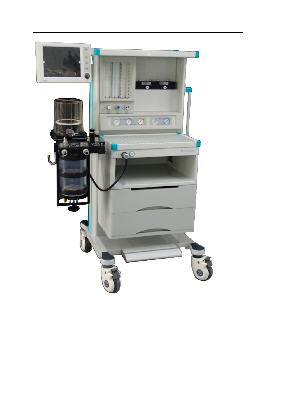
ANASTAZJA 7500 is a compact and integrated anesthesia transmitting system. The breathing
machine not only provides patients in operation with auto ventilation, but also monitors and
displays the patient’s various parameters. The ventilator used in the system is controlled by a
microprocessor.
The anesthetic ventilator controlled by microprocessor of ANASTAZJA 7500 includes monitor
internally, volume mode, and other functions optional. It can be used for communication with
cardiac blood vessel and monitor of breathing gas by serial interface.
Not all the optional functions available may be included in the manual. It is also possible to add
other equipment to the top or middle of this system for added functions. For more information
with respect to the existing product, please feel free to contact the local representatives.
WARNING: The user of ANASTAZJA 7500 must be professional and trained.
WARNING: ANASTAZJA 7500 is unsuitable for use in a magnetic resonance
imaging (MRI) environment.
1.1.1 Range for used
ANASTAZJA 7500 is applicable for patients of over 25 Kg with standard set and for child of over
12 Kg with cycles and CO2 monitoring device of child.
WARNING: ANASTAZJA 7500 is not to be used with infant.
01/2008 1-1
Page 12
ANASTAZJA 7500 User Manual
Figure 1-1 ANASTAZJA 7500
1-2 01/2008
Page 13
1 Introduction
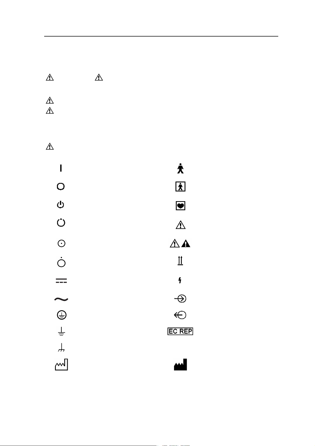
1.2 Symbols Used in the Manual and in the Equipment
Warnings and Cautions indicate all the possible dangers in case of violation of the
stipulations in this manual. Refer to and follow them.
WARNING: indicates potential hazards to operators or patients
CAUTION: indicates potential damage to equipment
Instead of illustrations, other symbols may also be utilized. Not all of them may necessarily
appear in the equipment and manual. The symbols include:
CAUTION: This manual complies with EN 1041.
ON(Power)
OFF(Power)
Stand-by
Stand-by or preparatory state
for a part of the equipment
ON only for part of the
equipment
OFF only for part of the
equipment
Direct Current
Alternating Current
Protectively earth
Type B equipment
Type BF equipment
Type CF equipment
Warning or Caution, ISO
7000-0434
NOTE: refer to the manual,
IEC601-1
This way up
Dangerous Voltage
Input
Output
Earth
Frame or chassis ground
Date of manufacture
SN
01/2008 1-3
CE Representative
Serial Number
Address of manufacture
Page 14
ANASTAZJA 7500 User Manual
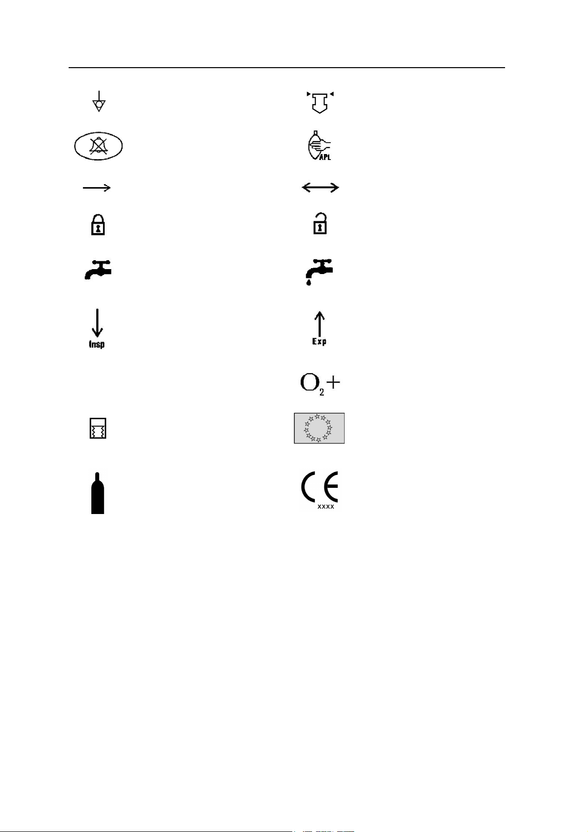
Equipotential
Alarm Silence
Movement in one direction
Lock
Close drain valve
Inspiration flow
View the reading on the top of
float
Reservoir bag location/manual
ventilation
Movement in two directions
Unlock
Open drain valve (release
liquid)
Expiration flow
134ºc
Autoclavable
Auto ventilation
Gas cylinder
Oxygen flush
CE Representative
The system, with this label
under the stipulations in the
operating manual, complies
with the requirements related
from 93/42/EEC. xxxx is the
certificate number used by
FARUM S.A. quality system to
certify authorizations
1-4 01/2008
Page 15

2 Anesthetic System Control
2.1 Anesthetic system
CAUTION: The anesthetic system is intended to be used with the following
monitoring devices, alarm systems, and protection devices:
-- pressure measuring in accordance with 8.1 of ISO 8835-2;
-- pressure limitation device in accordance with 51.101.1 of
IEC60601-2-13;
-- exhaled volume monitor in accordance with 51.101.4 of
IEC60601-2-13;
-- breathing system integrity alarm system in accordance with
51.101.5 of IEC60601-2-13;
-- continuing pressure alarm in accordance with 51.101.6 of
IEC60601-2-13;
-- O2 monitor in accordance with ISO 9918.
WARNING: To avoid explosion hazards, flammable anesthetic agents such as
ether and cyclopropane shall not be used in this anesthetic
workstation. Only anesthetic agents which comply with the
requirements for non-flammable anesthetic agents as specified in
this manual.
Halothane, desflurane, sevoflurane, enflurane,and isoflurane have
been found to be non-flammable agents.
WARNING: Independent means of ventilation (e.g. a self-inflating manually
powered resuscitator with mask) should be available whenever the
anesthetic system is in use.
WARNING: Do not use antistatic or electrically-conductive breathing tubes and
mask.
WARNING: Leakage and douse of liquid, such as anesthetic agent, bring on
dangerous states or malfunctions inside device.
01/2008 2-1
Page 16
ANASTAZJA 7500 User Manual
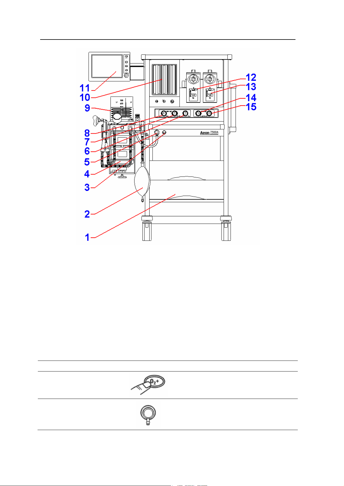
Figure 2-1 ANASTAZJA 7500 (front view)
1 Drawer 2 Reservoir Bag
3 Oxygen Flush 4 Absorber cycle
5 Common Gas Outlet 6 Air pipeline pressure gauge
7 N2O pipeline pressure gauge 8 O2 pipeline pressure gauge
9 Autoclavable Bellows Assembly 10 Flowmeters
Display Screen of anesthetic
11
ventilator
12 Enflurane Vaporizer
13 Isoflurane Vaporizer 14 O2 cylinder pressure gauge
15 N2O cylinder pressure gauge
Figure 2-1 each control function on the front view of Anastazja7500
Item Diagram Description
Press Oxygen Flush button to
3 Oxygen Flush
supply O2 to the breathing system
with high flow rate
Common gas
5
outlet
connects the anesthesia machine to
the breathing system
2-2 01/2008
Page 17
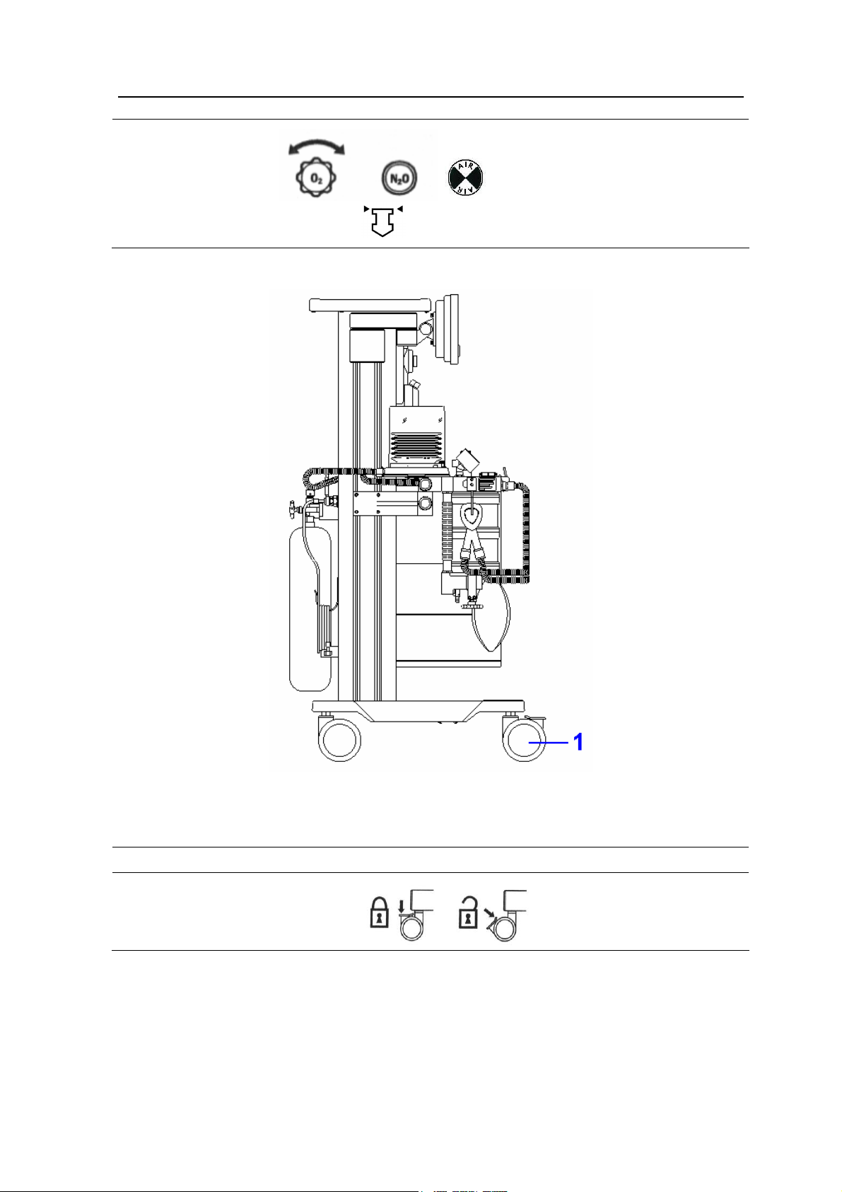
10 Flow Control
2 Anesthetic System Control
Turn the knob counterclockwise to
increase the flow; turn clockwise to
decrease the flow.
Read top of float when the
flowmeter is being read.
Figure 2-2 ANASTAZJA 7500 (side view)
Figure 2-2 each control function on the side view of Anastazja7500
Item Diagram Description
1
Castor(with break)
Push down to lock, and
pull up to unlock.
01/2008 2-3
Page 18
ANASTAZJA 7500 User Manual
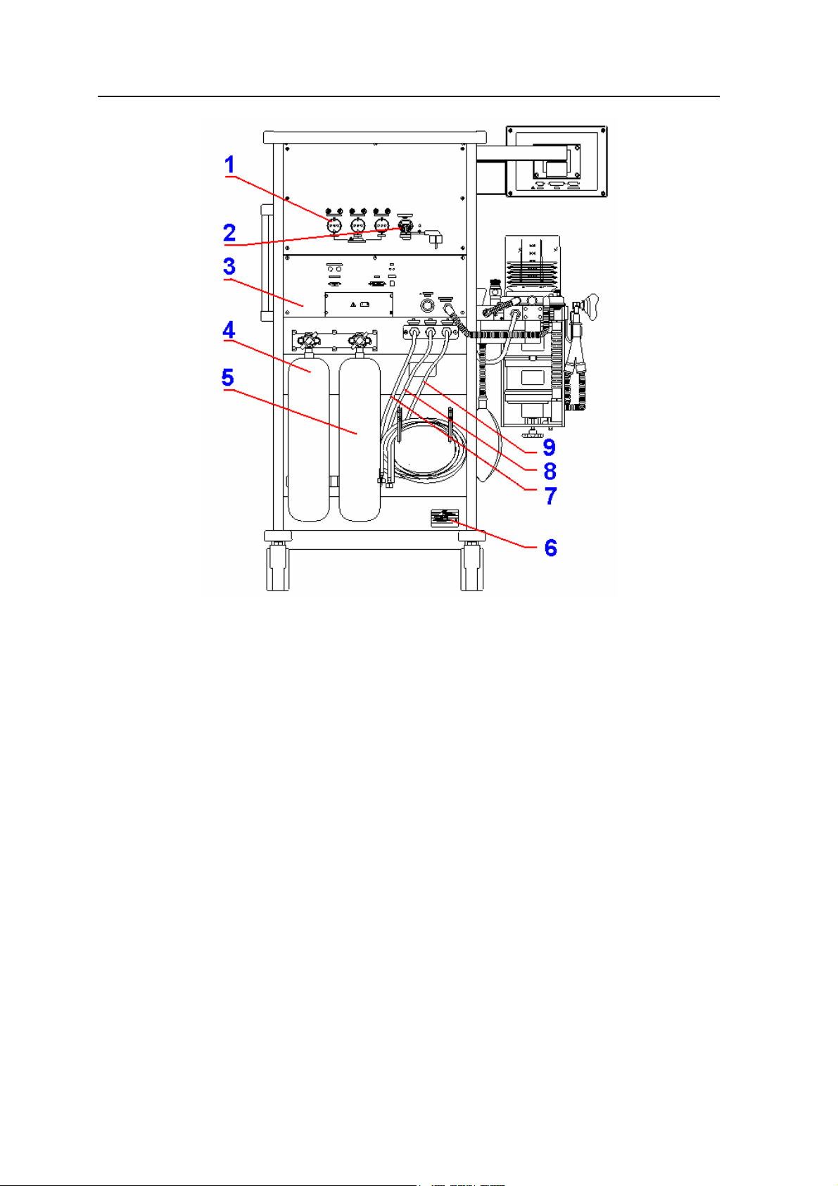
Figure 2-3 Anastazja7500 (back view)
1 Auxiliary mains socket outlet 2 Power socket
3 Anesthetic ventilator unit 4 N2O cylinder
5 O2 cylinder 6 Nameplate
7 Air pipeline 8 N2O pipeline
9 O2 pipeline
2-4 01/2008
Page 19
2 Anesthetic System Control
2.2 The Breathing system module
CAUTION: Any adult anesthetic ventilator system used together with the
anesthetic gas supply system must be in accordance with ISO
8835-2.
Figure 2-4 Breathing system module
1 Absorber mount release handle
2 Absorber (Carbon dioxide absorbent)
3 Exhalation Port / patient circuit connector
4 Exhalation valve
5 Airway pressure gauge
6 Bellows assembly (auto ventilation)
7 APL (adjustable pressure limit) valve
8 Inhalation valve
9 Manual reservoir bag/auto ventilation switch
10 Inhalation Port/Patient circuit port
11 Manual reservoir bag port
01/2008 2-5
Page 20
ANASTAZJA 7500 User Manual
Figure 2-4 the breathing system components function control
Item Diagram Description
2
Absorber mount
release
7 APL valve
Two soda lime canisters are
applied with a volume of 1500
ml for each so that it can be
continuously used for 6-8 hours
at full load. The water from the
reaction is drained via the
water collector underneath.
Adjust the pressure limit of
the breathing system
during the manual
ventilation process. The
readings are approximate.
The colors represent
different pressure zones.
Green represents safety
zone; yellow represents
transition zone; red
represents high pressure
zone. Adjusting ranges
between 0.19-6 kPa.
Auto ventilation “off” gas into
reservoir bag
Manual reservoir
9
bag/auto ventilation
switch
Auto ventilation “on” gas into
bellows
2-6 01/2008
Select manual ventilation
(reservoir bag) or auto
ventilation (ventilator).
Page 21
2 Anesthetic System Control
2.2.1 Absorber cycle
2.2.1.1 Structure
The functions of absorber cycle: absorb carbon dioxide; vent exhaust gas; assistant respiration;
monitor airway pressure; drain water generated by chemistry etc.
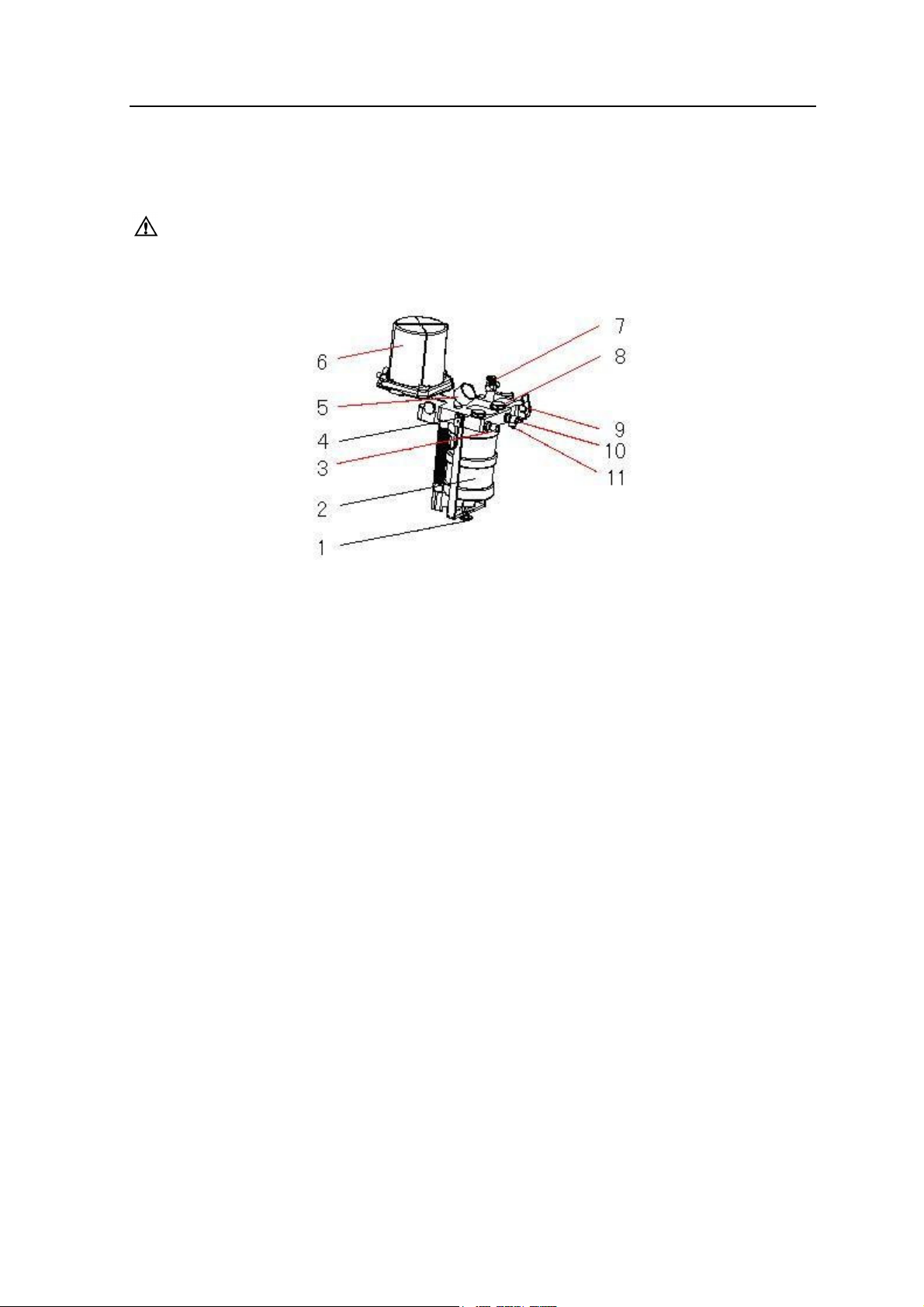
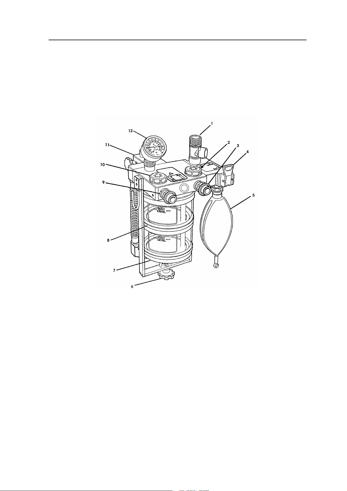
Figure 2-5 Absorber cycle
1. APL valve 7. Lower absorber
2. Inhalation valve 8. Upper absorber
3. Inspiratory port 9. Expiratory port
4. Bag/Ventilator Switch 10. Exhalation valve
5. Reservoir Bag 11. Fixation module
6. Handle 12. Airway Pressure Gauge
2.2.1.2 Principle
Gas flow schematic diagram, see Figure 2-6.
01/2008 2-7
Page 22
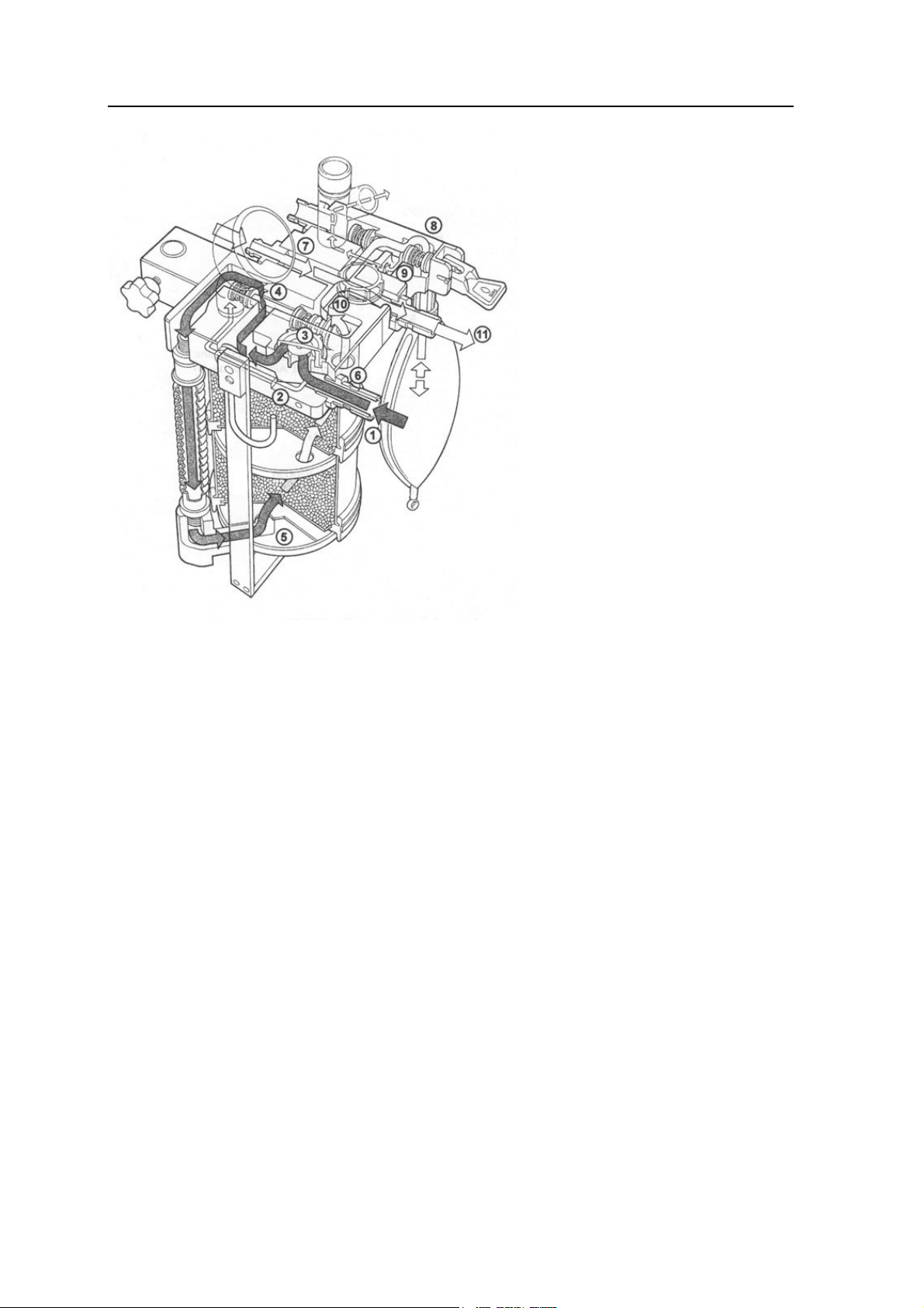
ANASTAZJA 7500 User Manual
Bag operating
1-Expiratory gas of patient;
2-Sampling airway pressure;
3-via exhalation valve
(unidirectional);
4-bypass switch (normal close);
5-enter into absorber;
6-leave absorber;
7-fresh gas compensation;
8-Bag/Ventilator (Bag ”ON”);
9-APL valve sampling path;
10- via exhalation valve;
(unidirectional);
11-Inspiratory gas
2-8 01/2008
Page 23
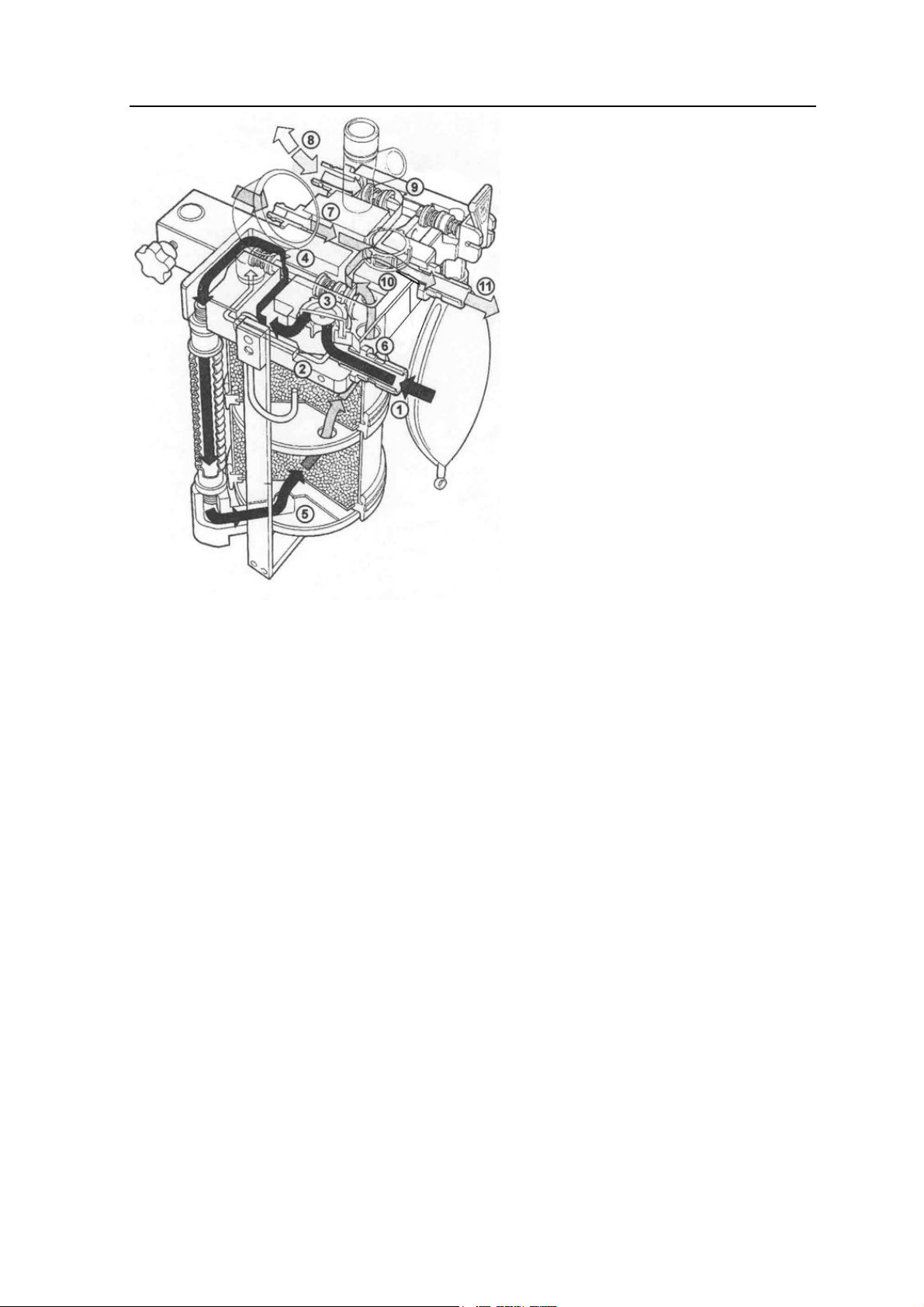
2 Anesthetic System Control
Ventilator operating
1-Expiratory gas of patient;
2-Sampling airway pressure;
3-via exhalation valve
(unidirectional);
4-bypass switch (normal close);
5-enter into absorber;
6-leave absorber;
7-fresh gas compensation;
8-gas of patient
9- Bag/Ventilator (Bag ”OFF”);
10- via exhalation valve;
(unidirectional);
11- Inspiratory gas
Figure 2-6 Gas flow schematic diagram
01/2008 2-9
Page 24
ANASTAZJA 7500 User Manual
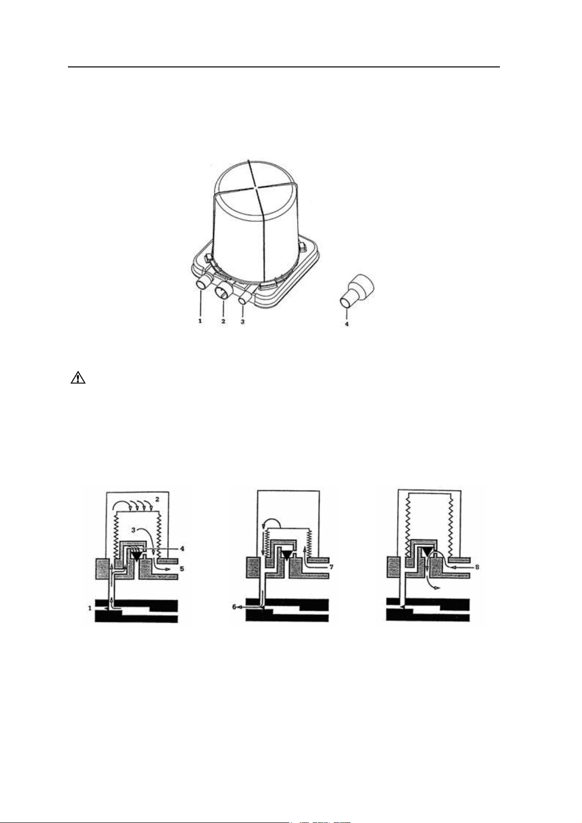
2.2.2 Bellows Assembly
2.2.2.1 Ports
Figure 2-7 Ports of bellows assembly
1 Breathing system connector 2 Exhaust gas port 3 Driven gas connector 4 Adapter
WARNING: Never connect exhaust gas port with sub-atmospheric system
directly. Or else leakage of breathing system generates.
The adapter can be used to connect the waste gas scavenging system to the bellows assembly
if the standard pipeline is used in the waste gas scavenging system.
2.2.2.2 ventilating circulation
Inhalation primary phase:
Exhalation primary phase:
Exhalation end phase:
1 Exhalation valve
2 Driving gas
6 Driving gas
7 From patient circuit
3 Gas of patient circuit
4 Spill-over valve
5 To patient circuit
2-10 01/2008
8 Excess gas of patient
circuit
Page 25
2 Anesthetic System Control
2.3 Vaporizer Control
Refer to operating and maintenance manual of vaporizer for more details.
WARNING: Anesthetic vapour delivery device used with anesthetic system
must be in accordance with ISO 8835-4.
2.4 Ventilator Control
CAUTION: Anesthetic ventilator accords with ISO 8835-5.
CAUTION: Monitoring conditions of this system: Ambient temperature: 29℃℃℃℃;;;;
Air temperature: 30℃℃℃℃;;;;Air humidity: 30%; Gas component: Oxygen.
CAUTION: If the temperature of sensor is lower than dew point of breathing
gas, vapour may coagulate on the surface of sensor, and oxygen
concentration monitored may be lower than practice value.
Optional function: SIMV mode, P-V loop and V-Flow loop can be added by code.
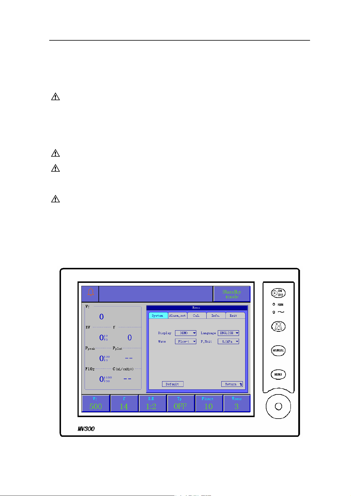
2.4.1 Front Panel
Front panel consists of display screen, keys, indicators, and a knob.
Figure 2-8 Front Panel
01/2008 2-11
Page 26
ANASTAZJA 7500 User Manual
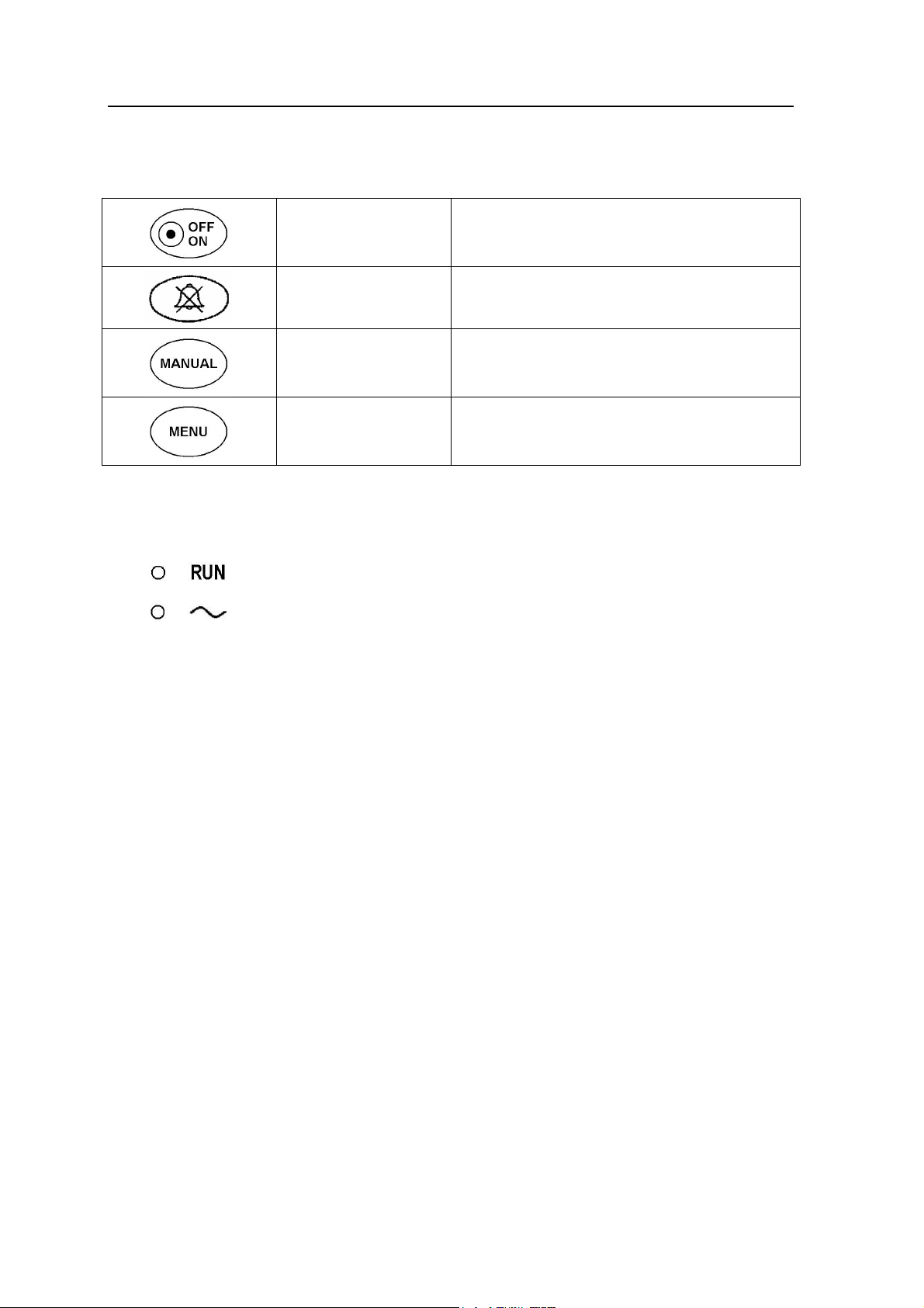
2.4.2 Keys
Mains switch key
Alarm silence key Press the key, alarm mutes for 110 seconds.
Manual mode key
Menu key
2.4.3 Indicators
Running Indicator The indicator brightly as ventilator operating.
AC Indicator The indicator brightly as AC power effectively;
Press the key and hold on for 2 second, you
can start or shut off ventilator.
Press the key, change original ventilation
mode to manual mode; Press again, back to
the original ventilation mode.
Press the key, a “Menu” window appeared on
the display screen, more details refer to
section 2.5.
The indicator dark as AC power failure.
2.4.4 Knob
The user may use the rotary knob to select the menu item and modify the setup. It can be
rotated clockwise or counter-clockwise and pressed like other buttons. The user may use the
knob to realize the operations on the screen and in the system menu and parameter menu.
The rectangular mark on the screen that moves with the rotation of the knob is called “cursor”.
Operation can be performed at any position at which the cursor can stay.
Operating method:
Move the cursor to the item where the operation is wanted
Press the knob
One of the following four situations may appear:
The background color of cursor may become into the contrast color, which
implies that the content in the frame can change with the rotation of the knob.
Pull down menu or dialogue box may appear on the screen, or the original menu
is replaced by the new menu.
Save setup.
2-12 01/2008
Page 27
2 Anesthetic System Control
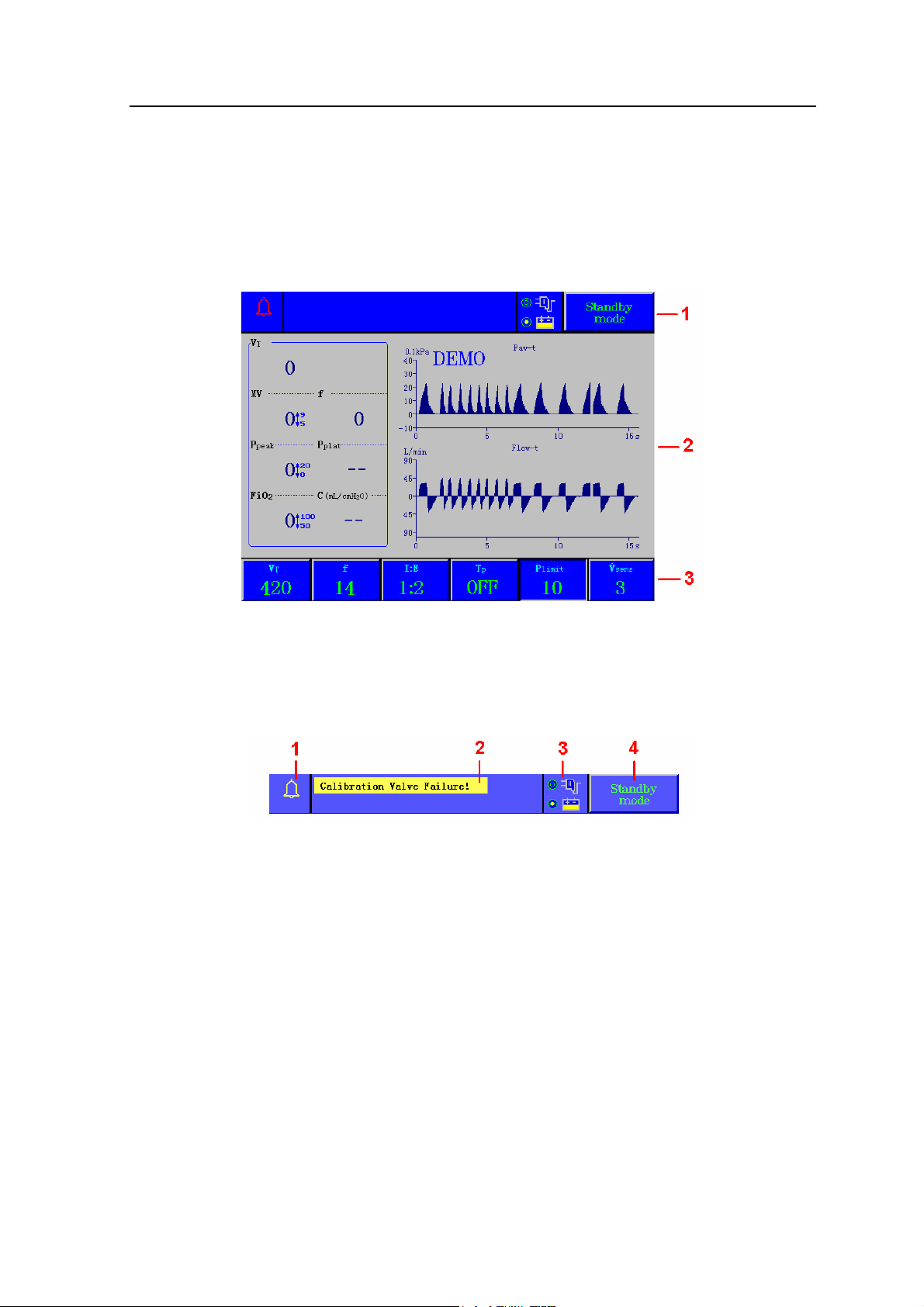
2.4.5 Display Screen
The display of the ventilator is a color TFT, which can display the monitoring and setting
parameters, waveforms, alarm information as well as displayed on the screen. See Figure 2-9.
The screen has three areas: information area (1), monitoring area (2), and parameter setup
area (3).
Figure 2-9 Display Screen
2.4.5.1 Information area
Information area lies on the top part of the screen, which is used to display the current status of
the ventilator and the patient. The information area contains following components:
Figure 2-10 Information area
1 Alarm bell
When alarm appears, the color of alarm bell accords with the background color of the
upper prior alarm message; press alarm silence key, “X” dashed line appears on the alarm
bell, and 110 seconds counts down. More details refer to section 8.1.
2 Alarm messages
Technical alarm and functional alarm supplied by the system, and not more than two alarm
messages displayed on the top of the screen. More details refer to section 8.2.
3 Power supply
Two kinds of power supply: AC power external and internal battery.
4 Ventilation mode
Five ventilation modes: VCV mode, Pressure mode, SIMV mode, Manual mode, and
Standby mode.
Turn and press the knob to setup ventilation mode required, and press again to save it.
01/2008 2-13
Page 28

ANASTAZJA 7500 User Manual
2.4.5.2 Monitoring area
Monitoring area has two parts: Patient parameter and waveform.
Patient parameter is fixedly displayed in the left side of the monitoring area. It includes seven
parameters:
Tidal volume MV: Minute volume
VT:
f: Respiratory frequency P
P
: Pressure at the end of
plat
: Peak value of airway pressure
peak
FiO2: Oxygen concentration
inspiratory pause time
C: compliance
Waveform is displayed in the right side of the monitoring area. It has four types:
Flow-t waveform, V-t waveform, Paw-V loop and V-FLOW loop.
More details refer to section 3.5.
2.4.5.3 Parameter setup area
Parameter setup area lies on the bottom part of the screen. It includes:
VT: Tidal volume f: Breaths per minute
I:E: Inspiration to expiration time TP: Inspiratory pause time
P
: Maximum airway pressure limit
limit
V
: Triggering flow sensitivity
sens
setting
2-14 01/2008
Page 29
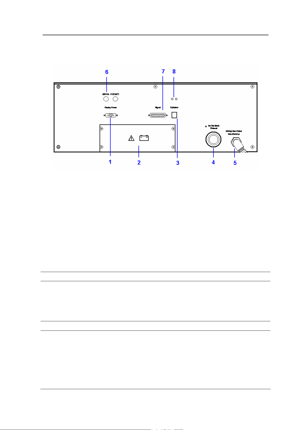
2.4.6 Rear Panel
2 Anesthetic System Control
Figure 2-11 Rear Panel
1 Display Power interface
2 Battery
3 O2 Sensor interface
4 Exhaust Port
5 Driven Gas Outlet
6 Fuse
7 Signal interface
8 P&V interface of sampling parallel line
Item Description
Use display power cable and signal cable to connect relevant
interface of rear panel with interfaces on rear of display screen
respectively.
Display power interface and signal interface: provide power supply
1&7
Display Power
interface and
Signal interface
and signal to the display.
2 Battery Refer to section 7.6
RJ 11 standard interface.
O2 Sensor
3
Interface
Use oxygen sampling line to connect O2 sensor with O2 sensor
interface.
Oxygen concentration value measured by O2 sensor is transmitted
to the ventilator through O2 sensor interface.
If no O2 sensor in the breathing system, the alarm message “No O2
sensor!” will be shown in the display screen.
01/2008 2-15
Page 30

ANASTAZJA 7500 User Manual
Don’t block exhaust port.
It is only a outlet of driven gas. Safety valve inside exhaust port may
4 Exhaust Port
be used to limit maximum of airway pressure. When airway
pressure exceeding the maximum, the safety valve will open and
exhaust for protecting airway of patient.
The maximum airway pressure is 6 kPa.
Size: male 16 mm taper
Use thread-tube to connect driven gas outlet with driven gas inlet of
bellows.
5 Driven Gas Outlet
6 Fuse
8 P&V interface
Inspiratory phase: gas from ventilator drives bellows to make fresh
gas enter into the airway;
Expiratory phase: return gas from the airway drives bellows to make
gas from ventilator exhaust through exhaust port.
250V 1A ∅5X20(T), more details refer to section 7.5.3
Connect sampling parallel line to P&V interface, the other end to
probe.
It provides basis for monitoring and troubleshooting that the real
time airway pressure is transmitted to the ventilator.
Parameter monitored such as VT and MV, are calculated by
ventilator basing on the flow via the probe.
CAUTION Ensure sampling line and probe connect
right, avoid liquid entering and leakage.
—— Probe of sampling and sampling parallel line
Flow of breathing cycle is measured by means of pressure
difference.
Avoid water entering into the probe and sampling parallel line in the
process of operating, otherwise parameter monitored will be
affected.
Ensure airtightness of sampling system, if sampling device is aging,
Accessory relatively
please replace it.
Sterilization: cleaning it with sterilizing agent, then swing it
mechanically. The formation and preparation of the agent must be
done in accordance with the direction given by the manufacturer.
—— O2 Sensor
Operation condition: 0.5 to 2.0 Bar. More details refer to section 7.4
2-16 01/2008
Page 31

2 Anesthetic System Control
2.5 Menu
2.5.1 Operating Guide
Calibrate or carry out other process, explanation will be displayed on the screen.
A demonstration like the following steps:
Step 1
Press ”MENU”
key, then display
a menu window
on the screen.
Step 2
Press knob to
select “Return”.
01/2008 2-17
Page 32

ANASTAZJA 7500 User Manual
Step 3
Turn the knob to
select option
required such as
“Wave”.
Step 4
Press the knob,
then a pull down
menu appears.
Step 5
Turn the knob to
select option
required.
2-18 01/2008
Page 33

Step 6
Press the knob
to save new
setup.
Go to next setup
or exit “System”
menu.
2 Anesthetic System Control
Step 7
Exit “System”
menu:
Turn the knob to
select”Return”,
and then press
it.
Step 8
Exit “Menu”:
1. Turn the knob
to select “Exit”
menu, and then
press it, or
2. Press “MENU”
key directly.
01/2008 2-19
Page 34

ANASTAZJA 7500 User Manual
2.5.2 Menu diagram
See Figure 2-12. Some functions are optional.
Press ”MENU” key, the Menu window
displaying on the screen.
Turn the knob to select a submenu.
Figure 2-12 Menu diagram
2-20 01/2008
Page 35

3 Operating Guide
3.1 Starting System
Step 1 Connect power supply
Plug the power cord into AC power outlet. The power
indicator light will be bright when power is connected.
Step 2 Power-on self-test
Press power ON/OFF key and last 2 seconds:
Display start, “RUN” indicator light brightly, and enter
LOGO interface; See Figure 3-1
Later, self-testing interface appears. See Figure 3-2
If self-testing succeeds, the display works normally and
the system is situated stand-by mode.
If failure, alarm message is displayed on the screen.
Please carry out operation in accordance with the prompt
information.
Figure 3-1 LOGO interface
01/2008 3-1
Page 36

ANASTAZJA 7500 User Manual
Figure 3-2 Self-testing
Figure 3-3 Self-test failure
WARNING if any unwonted malfunction appears, change bag / ventilator
switch to manual mode, stop mechanical ventilating.
3-2 01/2008
Page 37

3.1.1 Alarm Limit Set
Step 1
Press ”MENU” key,
then display a menu
window on the screen.
Step 2
3 Operating Guide
Turn the knob to
select “Alarm_set”
submenu.
Step 3
Press the knob to
select “Return”.
01/2008 3-3
Page 38

ANASTAZJA 7500 User Manual
Step 4
Turn the knob to
select option required.
Step 5
Press the knob, the
grounding of option
displays different color
and high brightness.
Step 6
Turn the knob to
adjust the value.
3-4 01/2008
Page 39

Step 7
Press the knob to save
the new adjustment.
Go to next setup or
exit “Alarm_set” menu.
Step 8
Exit “Alarm_set”
menu:
3 Operating Guide
Turn the knob to
select ”Return”, and
then press it.
Step 9
Exit “Menu”:
1. Turn the knob to
select “Exit” menu,
and then press it, or
2. Press “MENU” key
directly.
01/2008 3-5
Page 40

ANASTAZJA 7500 User Manual
3.1.2 Restore Default Set
Restore default setting includes:
Wave and P_unit items in the system submenu;
All items in the alarm_set submenu.
In a state of default, waveform display and pressure unit is “Flow-t” and ” 0.1kPa” respectively;
about details of alarm setting refer to section 8.4.
Step 1
Press ”MENU” key,
then display a menu
window on the screen.
Step 2
Press the knob, the
cursor point to
“Return” automatically.
3-6 01/2008
Page 41

Step 3
Turn the knob to select
“Default”.
Step 4
Press the knob, and
then display a
dialogue box on the
menu.
3 Operating Guide
Step 5
Turn the knob to
select “Yes”, and then
the state of “Wave”
and “P_Unit” restore
default setup. See
section 8.4.
01/2008 3-7
Page 42

ANASTAZJA 7500 User Manual
Step 6
Exit “System” menu:
Turn the knob to
select ”Return”, and
then press it.
Step 7
Exit “Menu”:
1. Turn the knob to
select “Exit” menu,
and then press it, or
2. Press “MENU” key
directly.
3-8 01/2008
Page 43

3.1.3 Ventilation Mode Set
Current ventilation mode shown at top
right corner of the display, with arrow
pointed up. See figure 3-4.
Standby mode
VCV mode
Pressure mode
SIMV mode
Manual mode
Step 1
Turn the knob; make cursor point to the current ventilation mode.
Figure 3-4
3 Operating Guide
CAUTION Exit the menu before carrying out this step.
Step 2
Press the knob to make sure the grounding changed.
Step 3
Turn the knob to select ventilation mode required.
Step 4
Press the knob to save the setup.
01/2008 3-9
Page 44

ANASTAZJA 7500 User Manual
3.1.4 Ventilator Control Set
1. Standby mode: all parameters can be adjusted.
2. SIMV mode: f
replace f; TP and Plimit displays “- -”, it means unadjusted.
IMV
Adjustable range:
VT: 0, 50 ~ 1500 mL
f
: 1 ~ 40 times
IMV
TI: 0.5 ~ 4.0s
Vsens: 1 ~ 30L/min
3. VCV mode: Plimit and Vsens displays “- -”, it means unadjusted.
According to VT, f, I:E, TP, the flow of inspiratory phase can be calculated by the following
formula:
Flow= VT ×(I+E)× f/(1000*I)(L/min)
Gas flow limit: lower: 5L/min; upper: 75L/min
4. Pressure mode: TP and Vsens displays“- -”, it means unadjusted.
5. Manual mode: all parameters displays“- -”, it means unadjusted.
Steps of setting refer to section 3.1.3.
3-10 01/2008
Page 45

3 Operating Guide
3.2 Starting Auto Ventilation
WARNING: Before getting started, make sure to set the patient circuit installing
and controlling correctly.
The following procedures assume that the system is in on position
and manual reservoir gas ventilating mode.
Step 1
Make sure the control settings coincide with the clinical settings.
Step 2
Set the reservoir bag / ventilator switch to auto
ventilation position.
Step 3
Select auto ventilation. Refer to section 3.1.3.
Step 4
Fill the bellows with O2 flush if necessary.
Auto ventilation ON (gas goes to the bellow)
01/2008 3-11
Page 46

ANASTAZJA 7500 User Manual
3.3 Shutting Off Auto Ventilation
Step 1
Before stopping the auto ventilation, make
sure the setting of manual circuit is complete,
and the setting of APL valve is correct.
This valve is used to adjust the pressure limit
of the breathing system during the manual
ventilation period.
Step 2
Set the reservoir bag / ventilation switch to
reservoir bag position
Select Manual ventilation, stop auto
ventilation (ventilator).
Auto ventilation OFF
(gas goes to the reservoir bag)
CAUTION: Take the monitoring reading of the anesthetic ventilator rather than
the observed reading of the bellows.
3-12 01/2008
Page 47

3 Operating Guide
3.4 Alarm
Alarm message displays on the top of screen.
The grounding of top prior alarms is red, but the grounding of middle prior and the lowest prior
ones are yellow.
3.4.1 Alarm tone
Judging prior level from the tone of alarms:
Top prior: 5 tones, 2 hurry, 9 seconds interval, repeat
Middle prior: 3 tones, 6 seconds interval, repeat
Low prior: 2 tones
3.4.2 Alarm Silence
When alarming, press alarm silence key, eliminate sound for 110 seconds.
During the silence, spare time displayed on the screen.
Details about alarm messages refer to chapter 8.
01/2008 3-13
Page 48

ANASTAZJA 7500 User Manual
3.5 Waveform
1 Paw-t waveform
Y-Axis: airway pressure; X-Axis: time. More details refer to section 10.8.8.
Figure 3-5 Paw-t waveform
2 Flow-t waveform
Flow scale: -90 to 90L/min. Time scale: 0 to 15s.
Time-Axis: Positive inspiratory direction above 0L/min level; minus expiratory direction
below 0L/min level; no gas flow on 0L/min level.
Figure 3-6 Flow-t waveform
3 V-t waveform
Y-Axis: Tidal volume, range: 0 to 1.2L.
Waveform of respiratory phase presents saw-shaped.
See Figure 3-7, (1) inspiratory phase; (2) expiratory phase.
Figure 3-7 V-t waveform
3-14 01/2008
Page 49

4 Paw-V Loop (Optional)
Y-Axis: pressure; X-Axis: tidal volume. See Figure 3-8.
Figure 3-8 Paw-V loop
5 V-FLOW Loop (Optional)
3 Operating Guide
Y-Axis: flow; inspiratory flow above 0L/min level; expiratory flow below 0L/min level.
X-Axis: tidal volume. See Figure 3-9.
Figure 3-9 V-FLOW loop
01/2008 3-15
Page 50

Page 51

4 Preoperative Checkout
4.1 Anastazja7500 Preoperative Checkout procedures
Test interval Preoperative Checkout should be done in the following situation:
Before use of the first patient each day.
Before use of each patient.
After repair or maintenance.
Test schedule is given in the table below:
Before use of the first patient each day Before use of each patient
System check:
Power failure alarm test:
Gas pipeline and gas cylinder test:
Flow control test:
Vaporizer installation and test
Alarm test:
Breathing system test:
Ventilator test:
WARNING: Do not use this system before the operation and maintenance
manual are read and understood.
• Whole system connection
• All warnings and cautions
• Using guide of each system module
• Testing method of each system module
Before using this system:
Breathing system test:
Ventilator test:
• Complete all tests of this section
• Test all the rest of system modules
If test failure, do not use this system. Please contact service representative.
01/2008 4-1
Page 52

ANASTAZJA 7500 User Manual
4.1.1 System Checkout
WARNING: make sure the breathing circuit is connected correctly and in good
condition.
Make sure:
1 Equipment is in good condition.
2 All the components are correctly connected.
3 Breathing circuit is correctly connected and in good condition; there is sufficient
absorbent in the breathing system.
4 Vaporizer is in lock position and is filled with sufficient anesthetic.
5 The connection and pressure of pipeline gas supply system are correct.
6 The connected cylinder valve should be closed if there are backup cylinders.
WARNING: Do not leave the cylinder valves open during pipeline gas supply
period; otherwise, cylinder gas supply will be used up and lead to
insufficient supply in case of pipeline malfunction.
7. The required emergency device is ready and in good condition.
8. The device for airway maintenance, organ cannula are ready and in good condition.
9. The applicable anesthetic and emergency medicine are ready.
10. Make sure the truckles are tight and locked and free of motion.
11. Connect the power cord to the AC power outlet. The power indicator light will light up
when power is connected.
If failure, that means no electric power supplying. Exchange other sockets, close
breaker, or replace power cord.
4.1.2 Mains failure alarm test
1 Press power ON/OFF key lasting 2 seconds, stand-by interface appears after
self-test.
2 After operating 5 minutes, pull out power cord.
3 Make sure that power off failure alarm occurs, it has the following characteristics:
• Alarm sound;
• “Mains Failure!” message displays on the screen;
• Mains icon flickering.
4 Connect power cord again.
5 Make sure the alarm eliminate.
4-2 01/2008
Page 53

4 Preoperative Checkout
4.2 Testing the gas supply pipeline and the gas cylinder
CAUTION: A user must confirm that gas supply is connected correctly; there
is no any disconnection, leakage, faulty connection in gas circuits
and pressure indicates correctly. Stop using and check gas
connections if abnormal.
CAUTION: To prevent from damage:
Open cylinder valve slowly.
Never control the flow with excessive force.
Skip step 2 if the system is not using cylinder gas supply.
1 Disconnect all pipeline gas supply and close all the cylinder valves.
• If the readings of the pipeline pressure gauge and cylinder pressure gauge are
not zero.
• switch on O2 supply.
• Adjust flow control to middle range.
• Make sure all the pressure gauges are reset to zero except the O2 pressure
gauge.
• Switch off O2 supply.
• Make sure the O2 pressure gauge is reset to zero. The low O2 supply alarm
should be on when pressure drops.
2 Make sure cylinders are fully filled:
• Open each cylinder valve.
• Make sure the pressure of each cylinder is high enough. In case the pressure is
insufficient, close the corresponding cylinder valve and install a fully filled
cylinder.
3 Test cylinder high pressure leak one by one.
4 Close flowmeters.
5 Open the cylinders.
6 Record the cylinder pressures.
7 Close the cylinder valves.
8 Begin to record the pressures after one minute. If O2 pressure drops to 5000kPa, it
means there is a leakage:
• If leakage exists, according to direction of section 5.5, replace a new sheet
gasket, and then tighten T handle.
• Perform this step again. If leakage exists all the same, do not use this system.
9 Step 5 ~ 7 should be repeated for all the cylinders. N2O pressure drop in one minute
should not exceed 700kPa.
10 Close all the cylinder valves.
01/2008 4-3
Page 54

ANASTAZJA 7500 User Manual
CAUTION: Do not leave the cylinder valves open during pipeline gas supply
period; otherwise, cylinder gas supply will be used up and lead to
insufficient supply in case of pipeline malfunction.
11 Connect pipeline gas supply.
12 Check pipeline pressure according to the table below:
ANSI (U.S. and International), Australia, Canada,
345kPa (50psig)
France and Japan
ISO, Italy, Scandinavia, South Africa, Spain and Switzerland 414kPa (60psig)
Austria and Germany 500kPa (75psig)
4-4 01/2008
Page 55

4 Preoperative Checkout
4.3 Monitoring Flow Control
WARNING: Refer to Step 1 to 13 of monitoring without oxygen for monitoring
without oxygen.
Refer to Step 1 to 13 of monitoring with oxygen for monitoring with
oxygen.
4.3.1 Monitoring without oxygen
WARNING: The monitoring system cannot be replaced by link system. The
fresh gas containing enough oxygen may not avoid the existence
of low oxygen mixture in the breathing circuit.
If N2O exists, it will pass through the system during the test, which
should be securely collected and removed.
Patients may be injured by improper gas mixture. The link system
should not be used if a proper ratio of O2 and N2O is not possible.
The following procedures can test whether the link system has
serious malfunction; however, it cannot determine whether the
calibration is correct.
CAUTION: The gas flow switch should be adjusted slowly. Do not turn it hard
when the reading of the flowmeter goes beyond the maximum or
minimum flow rate; otherwise, the control valve can be damaged
and the control will not work.
Follow the steps to test the flow control:
1. Connect the pipeline gas supply or open the cylinder valves slowly.
2. Turn clockwise all the flow control till the end (minimum flow).
3. Turn on mains switch.
4. Do not use this system if the battery is not fully charged or other ventilator failure alarm
occurs.
5. Make sure:
• The oxygen flow is between 25mL/min and 75mL/min.
• No gas flowing in any other flow tube.
• Step 6 and step 7 are only applicable for the N2O system test.
01/2008 4-5
Page 56

ANASTAZJA 7500 User Manual
WARNING: During Step 6 to Step 7, keep link systems working state.
Only adjust testing of control (N2O in step 6 and O2 in step 7).
Adjust flow according to order (N2O firstly O2 secondly).
If adjustable range exceeds, please adjust flow control to the
nearest place and perform this step again.
6. To test the flow increase of the link system:
• Turn clockwise the N2O and O2 flow control till the end (minimum flow).
• Turn counterclockwise the N2O flow control slowly.
• Set N2O flow control to the rate described in the following table. The O2 flow must be
higher than the minimum flow limit.
Set N2O flow to
(liters per minute):
O2 flow must be higher than the minimum flow
(liters per minute):
0.6 0.2
1.5 0.5
3 1.0
7.5 2.5
7. This step tests the function of the Link System when flow is reduced, you should:
Set N2O flow to
(liters per minute):
O2 flow must be higher than the minimum flow
(liters per minute):
6.0 2.0
3.0 1.0
0.6 0.2
8. Adjust full flow of all the gas to ensure that the flowmeter float must move smoothly.
9. Shut off the oxygen supply either by closing the oxygen cylinder valve, or by disconnecting
the oxygen pipeline supply.
10. Make sure:
• As pressure decreases, the oxygen-supply failure alarm must continuously sound.
• Disconnect the flow of nitrous oxide and oxygen to be sure that the oxygen flow will be
the last to stop.
• Air flow remains.
• If the oxygen is the driving gas of the ventilator, the oxygen-supply failure alarm must
continuously sound.
11. Turn all of the flow control valve knobs completely clockwise to the minimum flow.
12. Reconnect oxygen pipeline supplies or slowly open the oxygen cylinder valve.
13. Turn off mains supply.
4-6 01/2008
Page 57

4 Preoperative Checkout
4.3.2 Monitoring with Oxygen
WARNING: The monitoring system cannot be replaced by link system. The
fresh gas containing enough oxygen may not avoid the existence
of low oxygen mixture in the breathing circuit.
If N2O exists, it will pass through the system during the test, which
should be securely collected and removed according to safe and
eligible methods.
Patients may be injured by improper gas mixture. The link system
should not be used if a proper ratio of O2 and N2O is not possible.
CAUTION: Before continuous testing, perform test of the O2 monitoring
device according to step 8 in section 4.6.
Follow the steps to test the flow control:
1. Connect the pipeline gas supplies, or slowly open the cylinder valve.
2. Turn all of the flow control valve knobs completely clockwise to the minimum flow.
3. Turn on mains switch.
4. Do not use this system if the battery is not fully charged or other ventilator failure alarms
occur.
5. Make sure:
• The oxygen flow is between 25mL/min and 75mL/min.
• No gas flowing in any other flow tube.
• Step 6 and step 7 are only applicable for the N2O system test.
WARNING: During Step 6 to Step 7, keep link systems working state.
Only adjust testing of control (N2O in step 6 and O2 in step 7).
Adjust flow according to order (N2O firstly O2 secondly).
The oxygen sensor being used must be calibrated correctly.
6 To test the flow increase of the link system:
• Turn clockwise the N2O and O2 flow control till the end (minimum flow).
• Turn counterclockwise the N2O flow control slowly.
• Make sure that the oxygen flow is increasing. The concentration of the oxygen tested
must ≥ 21% during the complete process.
01/2008 4-7
Page 58

ANASTAZJA 7500 User Manual
7 To test the flow increase of the link system:
• Set the nitrous oxide flow to 9.0L/min.
• Set the oxygen flow to 3/min or higher.
• Turn the flow control valve knob of the oxygen clockwise slowly.
• Be sure that the oxygen flow is getting reduced. The concentration of the oxygen
tested must ≥
21% during the complete process.
8 Adjust all of the gas full flow to ensure that the flowmeter floats must move smoothly.
9 Shut off the oxygen supply either by closing the oxygen cylinder valve, or by disconnecting
the oxygen pipeline supply.
10 Make sure:
• As pressure decreases, the oxygen-supply failure alarm must continuously sound.
• Disconnect the flow of nitrous oxide and oxygen to be sure that the oxygen flow will be
the last to stop.
• Air flow remains.
• If oxygen is the driving gas of the ventilator, the oxygen-supply failure alarm must
continuously sound.
11 Turn all of the flow control valve knobs completely clockwise to the minimum flow.
12 Reconnect oxygen pipeline supplies or open the oxygen cylinder valve slowly.
13 Turn off mains supply.
4-8 01/2008
Page 59

4 Preoperative Checkout
4.4 Installing and testing of vaporizer
4.4.1 Installation
WARNING: Do not take the vaporizer away from the bypass valve with its
locking lever locked.
Do not use more than one vaporizer at the same time in this
system.
Install vaporizers in accordance with the following steps:
1. The vaporizer must be disassembled and reinstalled if its top is not horizontal.
2. Set the locking lever of the vaporizer so that it is locked.
3. Try to lift the vaporizer directly upwards so as to separate itself from the bypass valve, but
do not pull the vaporizer forwards. Be careful not to rotate it on the bypass valve.
4. As the vaporizer is taken away from the bypass valve, reinstall the vaporizer and then
follow step 1 to step 3. Do not use this system if you cannot put return the vaporizer to a
horizontal position on the bypass valve.
5. Try on opening two vaporizers at the same time.
• Testing any possible instance of each combination.
• If more than one vaporizer can be opened at the same time, disassemble and reinstall
them, then perform step 1 to step 5.
4.4.2 Testing Vaporizer Back Pressure
CAUTION: About performance testing of vaporizer refer to relevant instruction
for use.
01/2008 4-9
Page 60

ANASTAZJA 7500 User Manual
4.5 Testing alarm
1 Connect reservoir bag to patient end.
2 Set bag/ventilator switch to ventilator control.
3 Turn on mains switch.
4 Set control options:
Ventilation mode: VCV mode
Ventilator: VT: 700ml
f: 20bpm
I:E: 1:2
Plimit:40cmH2O
Anesthetic machine: O2 flow: minimum flow (25-75mL/min)
All other gas: close
Press O2 flush button to inflate bellows.
5 Set bag/ventilator switch to bag control, and then set to ventilator control again. Make sure:
• Auto ventilation start.
• Display right data on the screen.
• Bellow assembly up and down during auto ventilation.
6 Adjust O2 flow to 5L/min.
7 Make sure:
• Pressure at the end of expiration is 0cmH2O approximately.
• Right data displayed on the screen.
• Bellow assembly up and down during auto ventilation.
8 Test O2 monitoring and alarm:
• Remove O2 sensor from the absorber cycle, and confirm that O2 concentration
measured in the room air is about 21%.
• Adjust lower limit of O2 concentration to 50%, and confirm that “FiO2 low!!” alarm
occurs.
• Adjust lower limit of O2 concentration to 21% again, and confirm that the alarm
eliminates.
• Put O2 sensor back to the absorber cycle.
• Adjust upper limit of O2 concentration to 50% again.
• Press O2 flush to charge the breathing system, and confirm that “FiO2 high!!” alarm
occurs.
• Adjust upper limit of O2 concentration to 100%, and conform that the alarm eliminates.
• Let O2 sensor pass pure O2 for 2 minutes, and conform that O2 concentration
measured is about 100%.
4-10 01/2008
Page 61

4 Preoperative Checkout
9 Test low minute volume alarm:
• Turn to “Alarm_set” menu.
• Adjust lower limit of MV to 6L/min, and conform that “Minute Volume Low!!” alarm
occurs.
• Turn to “Alarm_set” menu again.
• Adjust lower limit of MV to 10L/min, and conform that the alarm eliminates.
10 Test high airway pressure alarm:
• View P
• Adjust lower limit of Paw to below P
• Adjust lower limit of Paw to above P
on the screen.
peak
, and conform that “Paw high!!!” alarm occurs.
peak
, and conform that “Paw high!!!” alarm
peak
eliminates.
11 Test low airway pressure alarm:
• Remove reservoir bag form the absorber cycle.
• Other alarm occurs, such as “Minute volume low!!”.
• Make sure that “Paw low!!” alarm occurs.
12 Test continuous high airway pressure alarm:
• Set control options:
APL valve: Set to the maximum value
Bag / Ventilator switch: Bag
• Set bag / ventilator switch to bag control, auto ventilation should stop.
• Block up patient end and press O2 flush button.
• Make sure that “Paw continuous high!!!” alarm occurs after 15 seconds approximately.
13 Turn off mains supply.
01/2008 4-11
Page 62

ANASTAZJA 7500 User Manual
4.6 Testing the Breathing System
Refer to the operating manual and:
Verify the non-return valve in the Breathing circuit module works normally:
The non-return exhalation valve will ascend during the exhalation period while it will descend
during the inhalation period.
WARNING: Objects in the breathing system can interrupt or disrupt the
delivery of breathing system gas, resulting in possible patient
death or injury:
Do not use any testing plug small enough to slip completely into
the breathing system.
4.6.1 Checking Oxygen flush Switch
Press the oxygen flush button (the sound of gas should be heard from the fresh gas outlet) then
release. The button must immediately drop back to its position and stop delivering the gas.
4.6.2 Testing Breathing System
Turn the switch of the anesthesia machine to Manual Bag. Pressure gauge is zeroed. APL
Valve knob should be fully clockwise to the maximum. Connect the wye connector to the test
lung.
Occlude the manual reservoir bag on the port below the switch. Press the oxygen flush button
or open the flowmeter to make the indication of the pressure gauge achieve 3KPa, then release
the button and close the flowmeter. After 20 seconds observation, the pressure indicated by the
pressure gauge must not exceed 0.3KPa.
4.6.3 Testing APL Valve
Adjust the positions of every switch and knob according to the method of testing Breathing
System Leak. Open the oxygen flow to 5 liters per minute. Adjust the APL valve to position the
pressure of the pressure gauge in different places respectively. The common gas outlet must
overflow some gas as the pressure is stable.
WARNING: Be sure that there is no any testing plug or foreign objects in the
Breathing System.
4-12 01/2008
Page 63

4 Preoperative Checkout
4.7 Testing Ventilator
1 Connect the test lung to the patient circuit port.
2 Set the Reservoir bag / Ventilator switch to the Reservoir bag position.
3 Turn on mains switch.
4 Set control options:
Ventilation mode: VCV mode
Ventilator: VT: 700ml
f: 20bpm
I:E: 1:2
Plimit:40cmH2O
Anesthetic machine: O2 flow: less than 200mL
All other gas: close
Press O2 flush to charge bellows.
5 Set the bag / Ventilator switch to ventilator control.
6 Press the Oxygen flush button to inflate the bellows.
7 Ensure:
• Auto ventilation start.
• No low pressure alarm.
• Ventilator displays the correct data.
• The bellows ascend and descend during the period of auto ventilation
8 Set the O2 flow control to 5L/min.
9 Ensure:
• Ending expiratory pressure is about 0 cmH2O.
• Ventilator displays the correct data.
• The bellows inflate and scavenge during the period of auto ventilation.
10 Set the ventilator control and alarm limits to the proper clinical level.
11 Turn off mains supply and close all valves of gas cylinders if not to use the system.
12 Ensure that the things in the following table should be prepared completely.
Apparatus: Airway maintenance
Manual ventilation
Organ cannula
anesthesia and emergent drugs applicably
01/2008 4-13
Page 64

ANASTAZJA 7500 User Manual
13 System preparation:
• Close all vaporizers.
• Open the APL valve.
• Set the bag / ventilator switch to bag control.
• Set all the flow controls to the minimum.
• Be sure that the breathing system connects correctly
WARNING: Be sure that the breathing system connects correctly.
WARNING: Flush the anesthesia machine for at least one minute by using O2
with 5L/min flow speed to remove unnecessary mixed gas and
objects in the system before connecting the equipment to the
patient end.
WARNING: Anesthesia equipment must be connected to the waste gas
scavenging system to outlet the waste gas to prevent the staff
working in the operating rooms from injury.
This requirement must be followed in the testing and clinical
application.
4-14 01/2008
Page 65

5 Installing and Connecting
CAUTION: O2 monitoring must be used on this equipment. For the related
stipulations, refer to local standards.
CAUTION: According to the European standard EN 740 and International
Standard IEC 60601-2-13 / ISO 8835-1, this equipment must use
expiratory volume monitoring, O2 monitoring (in accordance with EN
12342 or ISO 7767) and CO2 monitoring (in accordance with EN 864 or
ISO 9918).
CAUTION: Anesthetic monitoring (in accordance with ISO 21647:2004) must
be made as the anesthetic vaporizer is being used according to the
European standard EN 740 and International Standard IEC
60601-2-13 / ISO 8835-1.
WARNING: Operating room environment can be influenced by the expiratory
gas. Some unexpected dangers may occur if the anesthetic has
been not tested for a long time. The operator must dispose of
expiratory gas in a timely fashion according as required, and
examine other items to minimize the chances of danger and
malfunction.
WARNING: Be sure the gas pipeline supply hoses and the breathing circuit
components are non-poisonous, do not cause patient allergy, and
do not create dangerous by-product through reaction with the
anesthesia gas or the anesthetic.
WARNING: To prevent generating wrong data and malfunction, please use the
cables, hoses, and tubes from FARUM S.A..
CAUTION: It is dangerous if there is anesthetic in the absorber. Measures
must be made to prevent the soda lime in the absorber from drying.
Turn off all the gas supplies after finishing using the system.
CAUTION: This system can be operated correctly under IEC 60601-1-2
interference. Higher-level interference may cause alarm and result
in auto ventilation suspension.
CAUTION: To avoid equipment false alarm caused by high strength electric
field:
• Put the electricity surgical conducting wire far from the place
where the breathing system and the O2 sensor are put on.
• Do not put the electricity surgical conducting wire on any parts
of the anesthetic system.
01/2008 5-1
Page 66

ANASTAZJA 7500 User Manual
CAUTION: To protect the patient, as the electricity surgical equipment is being
used:
• Monitor and ensure that all the life supporting and monitoring
equipment are operated correctly.
• Ensure that the backup manual ventilator can be used
immediately in case that electricity surgical equipment cannot
secure the use of ventilator.
• Never use electrical conduction masks or hoses.
5.1 Installing Product
5.1.1 Shelf
Unpack the bottom package, take out the shelf
and lock its truckles so it cannot move freely.
5.1.2 Breathing circuit limb
Connect the breathing circuit limb to its
mounting tracks, then tighten the screws.
5.1.3 Absorber cycle
When installing, hold the top plate of the
breathing circuit with both hands, connect the
position fixing hole to the limb post, sit it on the
limb post, then tighten the knob .
1 knob
2 fixing hole
3 bolt hole
5.1.4 The bellows Assembly base
Connect the bellows assembly base to the bolt hole (3) of the absorber cycle, then tighten the
screws.
5-2 01/2008
Page 67

5 Installing and Connecting
5.2 Installing Absorber
CAUTION: The ANASTAZJA 7500 shall comply with configurations and
conditions under which clause 24 of the General Standard IEC
601-1.
WARNING: Follow the proper security measures:
• Do not use the absorber if the anesthetic is chloroform or
trichloroethylene.
• Avoid to let the skin or eyes touch the materials in the absorber.
Clean the affected part immediately and seek medical attention
if materials come in contact with skin or eyes.
• Do not replace absorber during the period of ventilating.
• Replace the absorbent often to prevent the deposition of
non-metabolism gas as the system is not on.
• Check the color of the absorbent after finishing each case. The
original color of the absorbent may be restored when not in
use. Refer to the labels of the absorbent for the details.
• Carbon monoxide is released if completely dried absorbent
contact with the anesthetic. Replace the absorbent for security.
• Perform leakage testing of breathing system in bag control
mode after disassembling the absorber.
The absorber in this system can be used repetitious.
The capacity of each absorber is 1500mL. It is recommended to use Medisorb absorbent.
Only air, oxygen, carbon monoxide, halothane, enflurane, isoflurane, sevoflurane and can
desflurane be used for the absorber.
5.2.1 When to replace absorbent
Changed color of the soda lime in the absorbent indicates that it has absorbed the carbon
dioxide; however, this color is not 100% accurate. To decide whether to replace the absorbent,
use CO2 monitoring machine.
Remove the changed-color absorbent immediately. The soda lime will restore its original color
several hours later and that may mislead the operator.
01/2008 5-3
Page 68

ANASTAZJA 7500 User Manual
5.2.2 Disassembling Absorber
The absorber is reusable. Follow the disassembling procedures:
Turn on drain valve to get rid of water
1
generated by chemical reaction.
2 Rotate the handle clockwise to
disassemble the absorber.
5.2.3 Filling Absorbent
1 Remove the absorbent of absorber.
2 Cleaning and sterilization refer to section 6.3.
3 Fill the absorber with fresh absorbent after dryness. Wipe soda lime fell on the edge of
absorber, and then install it back. Make sure the airtightness is well, and that no leakage
and spillage.
5-4 01/2008
Page 69

5 Installing and Connecting
5.3 Connecting tubes and lines
CAUTION: CO2 monitor (in accordance with ISO 9918) should be connected at
elbow bend of patient end.
CAUTION: Anesthetic agent monitor (in accordance with ISO 21647:2004)
should be connected at pipe T installed inspiratory port.
CAUTION::::
O2 sensor should be connected at pipe T
installed inspiratory port.
1 O2 sensor connector
2 pipe T
01/2008 5-5
Page 70

ANASTAZJA 7500 User Manual
5.4 Connecting Gas and Electricity
WARNING: IEC 60601-1-1 applies both for combination of items of medical
electrical equipment and for combinations of at least one item of
medical electrical equipment with one or more items of
non-medical electrical equipment. Even if there is no functional
connection between the individual pieces of equipment, when they
are connected to an auxiliary mains socket outlet they constitute a
medical electrical system. It is essential that operators are aware of
the risks of increased leakage currents when equipment is
connected to an auxiliary mains socket outlet.
WARNING: The equipment connected to the power outlet will increase electric
current leakage. Test electric current leakage regularly.
WARNING: A malfunction of the central gas supply system may cause more
than one or even all devices connected to it to stop their operation
simultaneously.
CAUTION: Disconnect the anesthetic workstation from the gas supply after
use to prevent contamination or pollution of the pipeline system.
CAUTION: Only the medical gas supply should be used. Other types of gas
supply may contain water, oil or other pollutants.
WARNING: All connectors of gas supply have different dimensions and
structures. It can avoid wrong operation occurs.
5.4.1 AC inlet
AC Power:
230VAC 50Hz;
5.5A Max.
Fuse:
250V6A, ∅5X20(F)
Clasp can stop power cord breaking off.
WARNING Switch the anesthesia machine to backup battery in case of AC
failure alarm, and prompt alarm message displaying on the screen.
5-6 01/2008
Page 71

5 Installing and Connecting
5.4.2 Auxiliary mains socket outlet
CAUTION Auxiliary mains socket outlets operator- accessible should be not
more than four when in use ANASTAZJA 7500.
This label displays the voltage of the power supply and the rated ampere value of the circuit
breaker.
Fuse: 250V 2A φ5X20(F)
Maximum current outlet: 1.5A (each); 4.5A (total)
5.4.3 Serial Port
RS-232 port on the rear of display can permit serial inlet and outlet of command and data.
Signal Standard: RS232C (EIA-574)
Signal Definition: DTE configuration
Interface: DB9/M
DB-9 Connector Pin Out
Pin # Signal Name Signal Description
1 CD Carrier Detect
2 RXD Receive Data
3 TXD Transmit Data
4 DTR Data Terminal Ready
5 GND Signal Ground / Common
6 DSR Data Set Ready
7 RTS Request To Send
8 CTS Clear To Send
9 RI Ring Indicator
01/2008 5-7
Page 72

ANASTAZJA 7500 User Manual
5.4.4 Pipeline gas supply inlet
Pressure inlet: 280 to 600 kPa
Pipeline connector: DISS (Diameter-indexed safety system) and NIST
(non-interchangeable screw-threaded).
It can prevent wrong connection generating.
5.4.5 Cylinder gas supply inlet
Cylinder connector: PISS (Pin-indexed safety system)
It can prevent wrong connection generating.
WARNING: The connecting procedures of O2 and N2O to the rear of the
anesthesia system have been provided. Each has a different
dimension to avoid user’s misoperation. A continuous pressure
monitoring device is installed in the front of the anesthesia system
to monitor each gas that connects with hospital supply pipelines.
5-8 01/2008
Page 73

5 Installing and Connecting
5.5 How to install gas cylinder (Testing high pressure leak)
CAUTION: Do not turn the cylinder valve on when the pipeline gas supply is
being used. The gas supply of the cylinder may be used out in case
of pipeline failure so that the backup supply may be insufficient.
1 Turn the handle T of the cylinder valve clockwise until it is tight. Close the valve of the
cylinder to be changed.
2 Release the yoke piece, then disassemble the cylinder.
3 Remove the valve cap from the new cylinder.
4 Keep the cylinder inlet away from all the objects which could be damaged by the release of
high pressure gas.
5 To clear the cylinder valve of any debris, use the cylinder wrench to briefly open, then close
the cylinder.
6 Install the cylinder.
• Align index pin with the basic hole of the gas cylinder.
• Close yoke piece and screw handle T.
7 Perform the high pressure leak test:
• Disconnect the pipeline gas supply.
• Close flowmeter.
• Open the cylinder.
• Close the cylinder.
• Record the pressure of the cylinder.
• If the pressure of the O2 cylinder drops more than 5000 KPa (725PSi) after one minute,
the high pressure circuit has an unacceptable leak.
• If the pressure of the N2O cylinder drops more than 690 KPa after one minute, the
high pressure circuit has an unacceptable leak.
Repairing gas leak
Install a fresh cylinder gasket and tighten the connector.
Repeat this step. Do not use this system in case of continuous gas leak.
01/2008 5-9
Page 74

ANASTAZJA 7500 User Manual
5.6 Connect gas scavenging transfer & receiving system
There are two ports releasing exhaust gas in this system. Connect the two ports to gas
scavenging transfer and receiving system with tubes.
1. APL valve
2. Exhausting port of bellows assembly
See the following figure; number 2 is the exhausting port.
5-10 01/2008
Page 75

6 Cleaning and sterilizing
WARNING: Use a cleaning and sterilizing schedule that conforms to your
institution’s sterilization and risk-management policies.
Refer to the material safety data policy of each agent.
Refer to the operating and maintaining manual of all the
sterilizing equipments.
Wear safety gloves and safety goggles. The O2 sensor may
leak and burn (by Chlorine Potassium Oxide) if damaged. Do
not inhale fumes.
Do not inhale fume.
CAUTION: To prevent damage:
Refer to the data supplied by the manufacturer if there are any
questions about the agent.
Never use any organic, halogenate or oil base solvent,
anesthetic, glass agent, acestone or other irritant agents.
Never use any abrasive agent to clean any of the components
(i.e. Steel wool, silver polish or agent).
Keep liquids far from the electrical components.
Prevent liquid from entering the equipment.
Do not immerse the synthetic rubber components more than
15 minutes: any longer will cause inflation, or accelerating
aging.
Only the components marked 134 are pressure-resistant and
heat-resistant.
The PH value of the cleaning solution must be from 7.0 to 10.5.
WARNING: Talc, zinc stearate, calcium carbonate, or corn starch that has been
used to prevent tackiness could contaminate a patient’s lung or
esophagus, causing injury.
CAUTION: Never immerse the circuit O2 sensor or flow sensor connector in
the liquid.
Never dispose the circuit O2 sensor connector by using hot press.
Do not clean the inner surface of the flow sensor. Clean the outer
surface by using a damp cloth.
Check if there is damage in the components. Replace if necessary.
01/2008 6-1
Page 76

ANASTAZJA 7500 User Manual
6.1 Cleaning and sterilization of pre-use first
Main unit
Breathing system
components
Absorber cycle Washing, refer to section 6.4
Bellows assembly Washing refer to section 6.5.4
Clean the machine’s panel and all surfaces with soft cloth soaked
with the water soluble sterilizing agent.
Sterilize main unit with ultraviolet radiation. Do not use acetic
hyctro peroxide or formaldehyde steaming.
Refer to section 6.2
6.2 Cleanable Breathing System Components
Threaded tubes
(contacted with
patient),mask, Y piece
connector, elbow bend,
reservior bag
Threaded tubes and bag
(repetitious)
Pipe T Washing to sterilize
Designed for using only once, not need to sterilize.
The waste should be recovered.
When to replace these expendable, products with medical level
and equal specification should be selected to use.
Washing to sterilize
Sampling probe and
parallel lines of flow
Components marked 134℃ are pressure-resistant and heat-resistant and can be cleaned by
hand or by machine (by using the mild agent with PH < 10.5). Scrub them thoroughly, then air
out to dry.
Clean the bellows assembly by disassembling them, or they will take longer to dry. To dry, hang
the bellows by from its top disk while spread fully. Moisture remaining in the folds of the bellows
may make the bellows tacky.
Reassemble the bellows assembly prior to the hot-press disposal. Put the bellows assembly up
side down when the hot-press disposal is being processed.
Clean with soap before use of each patient, and then washing in
disinfecting solution after airing.
6-2 01/2008
Page 77

6 Cleaning and sterilizing
6.3 Absorber
Refer to “Disassembling the Absorber” in the section 5.2.2
WARNING: The dry absorber may be very dangerous with the presence of any
anesthetic. Take proper measures to avoid dry soda lime in the
absorbent. Switch off all gas supplies after use.
6.3.1 Auto cleaning with agent or disinfector
Clean the absorber in the agent or disinfector according to the cleaning procedure.
Put the absorber in the heat-up room with the maximum temperature as 80ºC or with the room
temperature.
Higher-level sterilization is recommended if the agent and disinfector cannot sterilize
equipment.
6.3.2 Manual cleaning
Rinse the absorber.
Immerse the absorber completely in the sink with water and agent about three minutes at a
temperature of 40 ºC (104).
Rinse the absorber.
Higher-level sterilization must be performed after cleaning by hand.
6.3.3 Advanced Sterilizing
The absorber must be cleaned before advanced sterilizing.
The absorber can be placed in high temperature and high pressure conditions. The maximum
temperature recommended is 134ºC (273).
Put the soda lime into the absorber after being dried, and then tighten the knob. Clear all soda
lime debris.
01/2008 6-3
Page 78

ANASTAZJA 7500 User Manual
6.4 Absorber assembly
1 Inhalation valve and exhalation valve
Dismount the cover of the inspiration and expiratory valves by rotating it counter clockwise,
then clean all parts of them with the gauze soaked with water soluble sterilizing agent, after all
parts cleaned and dried recover it in original integration. Then one must check the leakage and
the movement of the inspiration and expiration valves in accordance with the required
regulation and checking procedure. Please handle all parts with care preventing any damage.
2 Absorber module
Either vapouring (not more than 50ºC) or immersion sterilization can be used in practice, in
case of immersion all sterilized parts must be dried with the high pressure air or oxygen before
reuse.
6.5 The Bellows Assembly
This section is about disassembling, assembling, cleaning and sterilizing the bellows assembly.
Read all content of this section before disassembling, assembling, cleaning and sterilizing the
bellows assembly to avoid equipment malfunction and patient injury.
CAUTION: The material of the bellows is made of latex.
6-4 01/2008
Page 79

6 Cleaning and sterilizing
6.5.1 Disassembling
To disassembling the bellows assembly:
(To assemble the bellows assembly, perform the steps in “Disassembling the bellows
assembly” in reverse order):
1 Loosen the screws from the bellows assembly base, then remove the bellows assembly.
2 Turn counterclockwise and remove the bellows housing.
3 Detach the bellows from the base plate.
01/2008 6-5
Page 80

ANASTAZJA 7500 User Manual
4 Detach the top plate from the bellows.
5 Remove the bellows assembly’s adapter ring.
6 Push the locking spring to the center, and then remove the plate.
6-6 01/2008
Page 81

6 Cleaning and sterilizing
7 Remove the pop-off valve diaphragm and the pop-off valve seat.
WARNING: Do not remove bellows assembly seat from diaphragm of the
pressure relief valve. This can distort the seat or diaphragm and
cause injury to the patient.
8 Push to the center, then remove the locking spring.
9 Remove the seal.
01/2008 6-7
Page 82

ANASTAZJA 7500 User Manual
6.5.2 Testing Function
WARNING: Do not use any object small enough to slip completely into the
system when occluding the breathing system for test purposes.
WARNING: Always check the breathing system components for foreign
objects before using on a patient.
This test is to ensure all the components are installed correctly. It cannot replace the system
test. The bellows assembling can be installed in case they requirement testing. Otherwise, they
need to be disassembled to check and replace broken components, then reassembled and
tested.
Hold the bellows assembly in hands vertically upwards to occlude the driving gas port before
installing.
Invert the bellows assembly. If the descending velocity of the bellows top is no more than 100
ml/min, this could be because the driving gas port is not properly sealed, bellows or seal is not
installed correctly or other component are broken and that the descending velocity exceeds the
limit.
6-8 01/2008
Page 83

6 Cleaning and sterilizing
Open the driving gas port to make the bellows fully spread, and then occludes the breathing
system connector.
Turn the bellows assembly so it faces vertically upwards. If the descending velocity of the
bellows top is no more than 100 ml/min this could be because the bellows or pop-off valve is
not installed correctly or other component are broken and the descending velocity exceeds the
limit.
01/2008 6-9
Page 84

ANASTAZJA 7500 User Manual
6.5.3 Assembly lists
1. housing 5. locking spring
2. bellows 6. seal
3. rim 7. bellows base
4. spill-over valve 8. holder
6-10 01/2008
Page 85

6 Cleaning and sterilizing
6.5.4 Cleaning and Sterilizing
Follow the machine and sterilizer manufacturer’s cleaning recommendations.
1 Cleaning
1) Disassembling.
WARNING: Never separate the diaphragm and the valve seat in a pop-off valve.
2) To prevent component damage, clean them lightly. Put the recommended nonenzyme mild
agent used for latex and plastic in hot water.
CAUTION: Do not immerse them more than 15 minutes to prevent inflation or
aging.
3) Rinse using clean hot water, and then dry.
CAUTION: Dry by hanging while fully spread. If moisture is left in the bellows,
they may become tacky.
4) Check the components if they are broken or damp, then perform the assembling and
function test.
5) Connect the bellow assembly, ventilator and breathing system.
6) Perform the preoperative check.
2 Sterilizing
Cleaning and sterilizing must be performed at the same time. Follow instructions for the
common bellows assembly sterilization methods.
Sterilizing after general patient use:
Clean the inner and outer parts of the bellows assembly in a soap-and-water solution. Rinse
thoroughly in cold water, and dry with soft cloth. Immerse plastic and latex instruments in
70-80% ethyl alcohol for half an hour. Take them out using the aseptically transmits pliers, then
store in clean containers. Repeat this step before next use. Components made of metal and
glass can be sterilized with high pressure steam. When the steam pressure is increased by the
autoclave, the rising temperature can concrete the bacterium protein rapidly to kill bacteria. In
1.05 KG/CM2 steam pressure, the temperature rises to 121C. All bacteria and most sorus can
be killed if this temperature is maintained for 15-25 minutes.
Sterilizing after special infection or infectious patient use:
Open pulmonary TB, pulmonary abscess, pseudomonas, tetanus aeruginosa infection, gas
gangrene or infectious hepatitis is included. Used bellows assembly components must be
completely sterilized according to preliminary and final disposal procedures.
01/2008 6-11
Page 86

ANASTAZJA 7500 User Manual
1) Preliminary disposal: Perform in accordance with the isolated disposal stipulation. Collect
and leave all the used bellows assembly components during the operation process in the
operating room. Immerse the bellows assembly components in the 1:1000 benzalkonium
bromide or 1-5% cresol for 30 minutes after finishing the operation.
2) Final disposal: perform the final sterilizing disposal after the bellows assembly components
are processed by the above-mentioned preliminary disposal:
• Scrub the bellows assembly in a soap-and-water solution. Thoroughly rinse in cold
water, and dry;
• If conditions permit, suffocating the components directly contacted with patients with
formald or oxirane is preferred, or perform immersing sterilization respectively. For
example: the components used by open pulmonary TB patients must be immersed in
3% cresol for 30 minutes; the components used by tetanus aeruginosa infection
patients must be immersed in 0.2% potassium permanganate for 30 minutes; the
components used by gas gangrene patients must be immersed in 0.1% chlorhexidine
for 30 minutes; the components used by pulmonary abscess patients must be
immersed in 0.1% benzalkonium bromide for 60 minutes; the components used by
pseudomonas patients must be immersed in 0.1% benzalkonium bromide for 120
minutes;
• the components being immersed need to be rinsed by water and dried for next use;
• scrub and rinse the components indirectly contacted with patients with 1-3% phenol
solution or soap-and-water solution and water. Irradiate them by using the ultraviolet
ray for 30 minutes if necessary.
6.5.5 Regular Maintenance
WARNING: Do not perform any tests and repairs when the equipment is being
used to avoid patient injury.
Perform the following check every 30 days to be sure that component worn by use and daily
cleaning are replaced in time.
Test by eyes
Separate the bellows assembly and anesthesia machine
Disassemble the bellows assembly
WARNING: Never separate the diaphragm and the valve seat in a pop-off valve
Check each component carefully to check for cracks, distortion, dissolution, inflation and other
physical changes. Replace them if necessary.
Assemble the bellows assembly, and then perform the leak test.
6-12 01/2008
Page 87

7 User Maintenance
WARNING: To avoid fire:
Use the lubricant approved for anesthesia or O2 equipments’
use.
Never oil or grease any anesthesia or O2 equipment. In general,
oils and greases oxidize readily, and – the presence of O2 – are
highly flammable.
All the covers or housings for the system use must be made of
static proof material, as static material may cause fire.
WARNING: Follow sterilizing control and security stipulations because used
equipment may contain blood and body fluids.
WARNING: Movable components and detachable parts can cause injury. Use
caution when system components and parts are being moved or
replaced.
WARNING: No shock and strong vibration should happen during
transportation because the glass cover of flowmeter is fragile.
WARNING: Disposal of waste or invalidated apparatus must be in accordance
with the relevant policies in local government.
7.1 Repair Policy
Do not use malfunctioning equipment. Make all necessary repairs, or have the equipment
serviced by an authorized FARUM S.A. Service Representative. After repair, test the equipment
to ensure that it is functioning properly, in accordance with the manufacturer’s published
specifications.
To ensure full reliability, have all repairs and service done by an authorized FARUM S.A.
Representative. If this is not possible, replacement and maintenance of parts in this manual
should be performed by a competent, trained individual with experience in Anesthesia Systems
repair, and appropriate testing and calibration equipment.
CAUTION: No repair should ever be undertaken or attempted by anyone
without proper qualifications and equipment.
It is recommended that you replace damaged parts with components manufactured or sold by
FARUM S.A.. After any repair work, test the unit to ensure it complies with the manufacturer’s
published specifications.
Contact the nearest FARUM S.A. Service Center for service assistance. In all cases, other than
where FARUM S.A. warranty is applicable, repairs will be made at FARUM S.A. current list
price for the replacement part(s) plus a reasonable labor charge.
01/2008 7-1
Page 88

ANASTAZJA 7500 User Manual
7.2 Maintaining Outline and Schedule
The following schedule is a recommended minimum standard based upon normal usage and
environmental conditions. Frequency of maintenance for the equipment should be higher if
your actual schedule is more than the minimum standard.
7.2.1 User maintenance
Minimum maintaining
Standard
Daily Clean the outer surface.
weekly Perform 21% O2 sensor calibration.
Planned maintaining Standard
Ventilate the system, open flowmeter, and make sure that
the float move up and down smoothly. It can prevent
blocking and clinging.
monthly Perform 100% O2 sensor calibration.
Test leakage of bellows assembly. (refer to section 6.5.2)
When cleaning and installing Check if any components are broken, and replace or
repair them if necessary.
As required Replace new gasket of cylinder gas supply.
Perform flow sensor calibration when flow waveform is
unusual.
Replace O2 sensor (one year generally).
Open the drain valve and replace absorbent in the
absorber.
7.2.2 Permissive Repairing
Minimum maintaining
Standard
6 months Test electric current leakage.
6 months Test mechanical safety valve.
Planned maintaining Standard
12 months Perform the maintenance, checking, testing, calibrating
and replacing of the components stipulated in this manual
by qualified individuals.
Notes: This is the recommended minimum maintaining
level. Perform the local policies if they are equal to or
higher than those in this manual.
7-2 01/2008
Page 89

7 User Maintenance
7.2.3 Useful life estimation
CAUTION: The useful life of the following parts should be considered in
normal environment and operating requirements.
Sampling probe and parallel lines 1500 times
Threaded tubes used repetitiously Not less than 1 year
Power cord, cables,
sampling line of O2 sensor
Bellows assembly (except bellows) 1500 times
Drain valve 5000 times
Battery 1 year
Lamp tubes of display 50,000 hours
Pipelines, pipe T 8 years
Main unit 8 years
8 years
7.3 Maintaining the Breathing System
Parts that are broken, crushed, worn or distorted must be replaced immediately when cleaning
the breathing system.
Refer to the sections corresponding to reassembly and testing.
7.3.1 Replace O2 sensor
WARNING: Comply with the relevant rules about biohazard when to dispose
sensor. No burning.
Replacement steps:
1 Pull out the connector of sampling line from O2 sensor.
2 Pull out the O2 sensor from the pipe T.
3 Replace it with a new one, and connect the sampling line to O2 sensor.
01/2008 7-3
Page 90

ANASTAZJA 7500 User Manual
7.3.2 Calibrate O2 sensor
WARNING: Do not perform the calibration steps when the system connected
with patient.
When to calibrate O2 sensor, ambient pressure must be equal with
monitoring pressure of delivering O2 in the patient circuit.
If operating pressure is not equal with calibrating pressure, the
accuracy of reading may exceed range stated.
7.3.2.1 Calibrate 21% O2 sensor
It will cost more than 3 minutes to perform 21% O2 sensor calibration.
Before performing 100% O2 sensor calibration, 21% O2 sensor calibration must be finished.
7-4 01/2008
Page 91

Step 1
Press “MENU” key, a
menu window appears
on the screen.
Step 2
Turn the knob to select
“Cal.” submenu.
7 User Maintenance
Press the knob, the
cursor appears on the
“Return”.
01/2008 7-5
Page 92

ANASTAZJA 7500 User Manual
Step 3
Turn the knob to select
“Oxygen Sensor”.
Press the knob, a new
menu named “Oxygen
Sensor Calibration”
cover the original.
Please attention to the
message on the menu.
Step 4
Press the knob, a new
window named “21%
Oxygen Sensor
Calibration” cover the
original.
Perform the operation in
accordance with the
prompt on the screen.
Disassemble O2 sensor
from absorber cycle, and
put it in the air not less
than 3 minutes.
7-6 01/2008
Page 93

Step 5
Press the knob to
perform the
calibration.
In the process of
calibration, the word
“Calibrating” displays
on the screen.
“CAL. finish.” will be displayed on the
window after the calibration succeed.
Then put O2 sensor back to the patient
circuit according to the prompt on the
window, and perform 100% calibration.
7 User Maintenance
If 21% calibration failure, the word “CAL
fault” displays on the window.
If the calibration failure occurs:
• Repeat these steps to calibrate it
again.
• If still failure, perform 100% oxygen
sensor calibration (step 7). And then
calibrate 21% O2 sensor again when
the 100% calibration succeeded. If
not, replace O2 sensor and then
recalibrate it.
01/2008 7-7
Page 94

ANASTAZJA 7500 User Manual
Step 6
Exit to “21% Oxygen
Sensor Calibration”
menu; please turn the
knob to select “Return”.
Press the knob, back
to ” Oxygen Sensor
Calibration” menu.
7-8 01/2008
Page 95

7 User Maintenance
7.3.2.2 Calibrate 100% O2 sensor
It will cost more than 3 minutes to perform 21% O2 sensor calibration.
Before performing 100% O2 sensor calibration, 21% O2 sensor calibration must be finished.
WARNING: Never to perform the calibration when the system connected with
patient.
Step 7
Turn the knob to
select ”100%” option.
Press the knob, a new
window named “100%
Oxygen Sensor
Calibration” cover the
original.
Perform the operation in
accordance with the
prompt on the screen.
01/2008 7-9
Page 96

ANASTAZJA 7500 User Manual
Step 8
Press the knob to
perform the
calibration.
In the process of
calibration, the word
“Calibrating”
displays on the
screen.
“CAL. finish.” will be displayed on the
window after the calibration succeed.
If 100% calibration failure, the word “CAL
fault” displays on the window.
If the calibration failure occurs:
• Recalibrate it.
• Reduce airway pressure and try it
again.
• If failure still exists, replace O2
sensor and perform 21% calibration.
Step 9
Press “MENU” key to exit directly.
7-10 01/2008
Page 97

7.3.3 Calibrate flow sensor
Step 1
Press “MENU” key, a
menu window appears
on the screen.
7 User Maintenance
Step 2
Turn the knob to select
“Cal.” submenu.
Press the knob, the
cursor appears on the
“Return”.
01/2008 7-11
Page 98

ANASTAZJA 7500 User Manual
Step 3
Turn the knob to select
“Flow sensor”.
Press the knob, a new
window named “Flow
Sensor Calibration”
covers the original.
Pay attention to the
prompt on the screen.
Step 4
Press the knob to
perform the calibration.
In the process of
calibration, the word
“Calibrating” displays on
the screen.
7-12 01/2008
Page 99

“CAL. finish.” will be displayed on the
window after the calibration succeeds.
Step 5
Turn the knob to
select “Return”
option.
7 User Maintenance
Press the knob,
back to “Cal.”
menu.
Step 6
Exit: Select “Return” and press knob, then turn to “Exit” menu and press it again; or press the
“MENU” key directly.
01/2008 7-13
Page 100

ANASTAZJA 7500 User Manual
7.3.4 Calibrate flow valve
Make sure:
• Pressure range of driven gas (oxygen): 280 to 600kPa
• All connections of tubes and lines should be correct
• Leakage of breathing system should comply with the requirements in section 4.6
• Operating 5min. at least in VCV mode: Vt=500, f=20, I:E=1:2, Tp=OFF
Calibrating:
Press “MENU” key, and perform flow sensor calibration according to the steps of section7.3.3.
Input “2020” on the following figure, and
press “OK”, then the calibrating starts until
“Calibration finish” displays on the
window. And the ventilation mode
becomes standby.
During the calibrating process, press the
“MENU” key to exit and the calibrating will
cease.
If the calibration failure, it may be because
the increase of tidal volume monitored is
non-linear, just contact eligible service
representative.
If password is wrong, see the following
figure.
To calibrate flow valve when there be a
difference of 30% between the value of
tidal volume monitored and the settings.
7-14 01/2008
 Loading...