

Page 1

Statement
Beijing Aeonmed Co, Ltd. (Aeonmed for short) holds the copyrights to this manual,
which is non-public published, and reserves the rights to keep it as a secure
document. Refer to this manual when operating, maintaining and repairing
Aeonmed products only. Anyone other than Aeonmed may not make it known to
others.
Proprietary materials protected by the copyright law are included in this manual. Any
section of it cannot be reproduced, copied, or translated into other languages
without any prior written approval from Aeonmed who reserves the copyright.
Everything written in this manual is considered to be correct. Aeonmed is not legally
responsible for any mistakes printed within and any damages caused by incorrect
installation and operation. Aeonmed does not supply privileges endowed by the
patent law to any other parties. Aeonmed is not legally responsible for the results
caused by patent law breaking and any rights of the third party violating.
Refer to this manual before any Aeonmed product is used. The manual includes
operating procedures which must be performed with cautiously, operations that may
result in non-normal working conditions and the dangers which may damage
equipment or cause bodily harm. Aeonmed is not responsible for the security,
reliability and function of the equipments in case that the dangers, damages and
non-normal phenomenon mentioned in this manual happen. Free repairs for these
malfunctions will not be provided by Aeonmed.
Aeonmed have the rights to replace any content in this manual without notice.
Manufacturer Responsibility:
Aeonmed is responsible for the security, reliability and function of the equipments
when to following conditions are adhered to:
Installation, adjustments, mending and repairs must be performed by
individuals authorized by Aeonmed;
Necessary electrical equipment and the working environment must be in
accordance with the national standards, professional standards and the
requirements listed in this manual;
Equipment must be used as instructed in the operating instructions.
i
Page 2

Aeon7400A User Manual
CAUTION: This equipment is not for family use.
CAUTION: Malfunctioning equipment may become invalid and cause bodily
injury if a set of effective and approving repairing proposals
cannot be submitted by the institution which is responsible for
using this equipment.
The paid theoretical framework diagram will be supplied according to customer
requirements by Aeonmed, plus calibrating method and other information to help the
customer, under the assistance of qualified technicians, repair the equipment parts
where can be done by customer himself based on the stipulation by Aeonmed.
Warranty:
Manufacturing techniques and materials:
For a period of one year from the date of original delivery, the components and
assemblies of this product is warranted to be free from defects manufacturing
techniques and materials, provided that the same is properly operated under the
conditions of normal use and regular maintenance. The warranty period for other
parts is three months. Expendable parts are not included. Aeonmed’s
under the above warranties is limited to repairing free of charge.
obligation
Free Obligations:
Aeonmed’s obligation under the above warranties does not include the
freight and other fees;
Aeonmed is not responsible for any direct, indirect or final product broken
and delay which result from improper use, alteration by using the
assemblies unratified and maintenance by anyone other than Aeonmed;
This warranty does not apply to the followings:
Improper use;
Machines without maintenance or machines broken;
The label of Aeonmed original serial number or mark is removed or
replaced;
Other manufacturers’ product.
ii
Page 3

Contents
Security, reliability and operating condition:
Aeonmed is not responsible for the security, reliability and operating condition of this
product in case that:
The assemblies are disassembled, extended and readjusted
This product is not operated correctly in accordance with the manual
instruction. The power supply used or operating environment does not
follow the requirements in this manual.
Return
Follow the steps in case that the product needs to be returned to Aeonmed:
1. Obtain the rights of return
Contact with the customer service of Aeonmed by informing them the number and
type of the product. The number is marked on the surface of the product. Return is
unacceptable if the number cannot be identified. Enclose a statement of the number,
type and the reason of return as well.
2. Transportation charges
Transportation and insurance charges must be prepaid by the user for transporting
the product to Aeonmed for repairing. (Customers charges is added with regard to
the products sold to non-Chinese mainland users)
iii
Page 4

Aeon7400A User Manual
NOTE:
Each Aeonmed product has a serial number, such as
Aeon7400A xx xx xx
Aeon7400A: machine model
the first xx : the year of manufacturing
the second xx : the month
the third xx : equipment number
Manufacture: Beijing Aeonmed Co., Ltd.
Address: No.4, Hangfeng Road, Fengtai Science Park, Fengtai
District, Beijing, China
European
Shanghai International Holding Corp. GmbH (Europe)
Representative:
Address: Eiffestrasse 80, 20537 Hamburg Germany
P.C.: 100070
Tel: +86-10-83681616
Fax: +86-10-63718989
E-mail: service@aeonmed.com
iv
Page 5

Contents
1 Introduction.........................................................................................................1–1
1.1 What’s Aeon7400A?......................................................................................1–1
1.1.1 Intended Use .........................................................................................1–1
1.2 Symbols.........................................................................................................1–2
1.3 Definition, abbreviation..................................................................................1–4
2 Anesthetic System Control................................................................................2–1
2.1 Anesthetic system .........................................................................................2–1
2.2 The Breathing system module ......................................................................2–7
2.2.1 Bellows assembly Ports.........................................................................2–9
2.2.2 Ventilating circulation...........................................................................2–10
2.3 Vaporizer Control.........................................................................................2–10
2.4 Ventilator Control.........................................................................................2–10
2.4.1 Front Panel .......................................................................................... 2–11
2.4.2 Rear Panel...........................................................................................2–16
3 Operating Guide..................................................................................................3–1
3.1 Starting System .............................................................................................3–1
3.1.1 Alarm Limit Set ......................................................................................3–1
3.1.2 Ventilator Control Set.............................................................................3–2
3.2 Starting IPPV Ventilation ...............................................................................3–3
3.3 Starting Manual Ventilation............................................................................3–4
4 Preoperative Checkout.......................................................................................4–1
4.1 Preoperative Checkout procedures...............................................................4–1
4.1.1 System Checkout...................................................................................4–3
4.1.2 Mains failure alarm test..........................................................................4–4
4.2 Testing gas supply pipeline and gas cylinder................................................4–4
4.3 Monitoring Flow Control ................................................................................4–7
4.4 Installing and testing of vaporizer................................................................4–10
4.5 Alarm testing ...............................................................................................4–10
4.6 Testing the Breathing System .....................................................................4–10
4.6.1 Checking Oxygen flush button............................................................. 4–11
4.6.2 Testing Breathing System.................................................................... 4–11
4.6.3 Testing APL Valve ................................................................................4–11
4.7 Testing Ventilator.........................................................................................4–12
v
Page 6

Aeon7400A User Manual
5 Installing and Connecting..................................................................................5–1
5.1 Installing Product ...........................................................................................5–3
5.2 Installing Absorber.........................................................................................5–5
5.2.1 When to replace absorbent....................................................................5–6
5.2.2 Disassembling Absorber........................................................................5–6
5.2.3 Filling Absorbent ....................................................................................5–7
5.3 Connecting tubes and lines ...........................................................................5–7
5.4 Connecting Gas and Electricity ...................................................................5–11
5.4.1 AC inlet ............................................................................................... 5–12
5.4.2 Auxiliary mains socket outlet .............................................................. 5–13
5.4.3 Pipeline gas supply inlet ..................................................................... 5–14
5.4.4 Cylinder gas supply inlet..................................................................... 5–14
5.5 Install gas cylinder (Test high pressure leak) ............................................. 5–15
5.6 Connect to AGSS ....................................................................................... 5–17
6 Cleaning and Disinfecting..................................................................................6–1
6.1 Cleaning and disinfection of pre-use first ......................................................6–2
6.2 Cleanable Breathing System Components ...................................................6–3
6.3 Absorber ........................................................................................................6–4
6.3.1 Auto cleaning with agent or disinfectant ................................................6–4
6.3.2 Manual cleaning.....................................................................................6–4
6.3.3 Advanced Sterilizing ..............................................................................6–4
6.4 Absorber assembly........................................................................................6–5
6.5 The Bellows Assembly...................................................................................6–5
6.5.1 Disassembling........................................................................................6–6
6.5.2 Testing Function.....................................................................................6–9
6.5.3 Bellows Assembly lists........................................................................ 6–12
6.5.4 Cleaning and Disinfecting ................................................................... 6–13
6.5.5 Regular Maintenance.......................................................................... 6–16
7 User Maintenance ...............................................................................................7–1
7.1 Repair Policy .................................................................................................7–2
7.2 Maintaining Outline and Schedule.................................................................7–2
7.2.1 User maintenance..................................................................................7–3
7.2.2 Permissive Repairing .............................................................................7–3
7.2.3 Useful life estimation..............................................................................7–4
7.3 Maintaining the Breathing System.................................................................7–4
vi
Page 7

Contents
7.4 Maintaining flow sensor.................................................................................7–4
7.5 Replacing fuses.............................................................................................7–5
7.5.1 Replacing fuse of mains supply.............................................................7–5
7.5.2 Replacing fuse of auxiliary mains socket outlets...................................7–6
7.5.3 Replacing fuse of the ventilator .............................................................7–6
8 Alarm and Troubleshooting...............................................................................8–1
8.1 About alarm ...................................................................................................8–1
8.2 Troubleshooting.............................................................................................8–2
8.2.1 Anesthesia machine ..............................................................................8–2
8.2.2 Anesthetic Ventilator..............................................................................8–3
9 Ordering information..........................................................................................9–1
9.1 Key components............................................................................................9–1
9.2 Bellows Parts List ..........................................................................................9–2
9.3 Accessories ...................................................................................................9–3
9.4 Expendable parts...........................................................................................9–4
10 Specifications and Operation Theory ......................................................... 10-1
10.1 Schematic diagram...................................................................................... 10-1
10.2 System technical specification .................................................................... 10-3
10.2.1 Drive..................................................................................................... 10-3
10.2.2 Flow ..................................................................................................... 10-4
10.2.3 Classification........................................................................................ 10-5
10.3 Power supply ............................................................................................... 10-5
10.4 Electromagnetic Compatibility ..................................................................... 10-6
10.5 Physical specification .................................................................................. 10-8
10.6 Environment requirements .......................................................................... 10-8
10.7 Breathing system technical specifications................................................... 10-9
10.7.1 Performance of ventilator................................................................... 10-10
10.7.2 Setting ventilation mode .................................................................... 10-10
10.7.3 Setting ventilating parameters ........................................................... 10-10
10.7.4 Gas dynamics performance................................................................10-11
10.7.5 Setting alarm parameters ...................................................................10-11
10.7.6 Volume and pressure..........................................................................10-11
10.7.7 Monitoring performance..................................................................... 10-12
vii
Page 8

Aeon7400A User Manual
viii
Page 9

1 Introduction
1.1 What’s Aeon7400A?
Aeon7400A is a compact and integrated anesthesia transmitting system. The
breathing machine not only provides patients in operation with IPPV ventilation, but
also monitors and displays the patient’s various parameters. The ventilator used in
the system is controlled by a microprocessor. Aeon7400A is intended for use in the
operating room and emergency department of hospital.
Not all the optional functions available may be included in the manual. It is also
possible to add other equipment to the top or middle of this system for added
functions. For more information with respect to the existing product, please feel free
to contact the local representatives.
WARNING: The user of Aeon7400A must be professional and trained.
WARNING: Aeon7400A is unsuitable for use in a magnetic resonance
imaging (MRI) environment.
1.1.1 Intended Use
Aeon7400A is applicable for patients of over 25Kg with standard configuration.
WARNING: Aeon7400A is not to be used for infant anaesthesia.
1–1
Page 10
Aeon7400A User Manual
1.2 Symbols
Warnings and Cautions indicate all the possible dangers in case of
violation of the stipulations in this manual. Refer to and follow them.
WARNING: indicates potential hazards to operators or patients
CAUTION: indicates potential damage to equipment
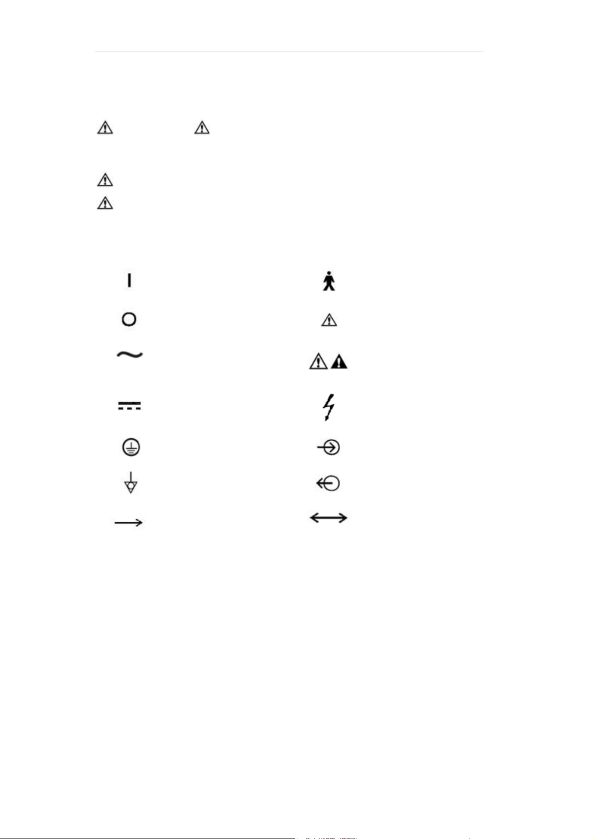
Instead of illustrations, other symbols may also be utilized. Not all of them may
necessarily appear in the equipment and manual. The symbols include:
ON(Power)
OFF(Power)
Alternating Current
Direct Current
Protectively earth
Equipotential
Movement in one
direction
Type B equipment
Warning or Caution, ISO
7000-0434
NOTE: refer to the
manual, IEC601-1
Dangerous Voltage
Input
Output
Movement in two
directions
1–2
Page 11
1 Introduction
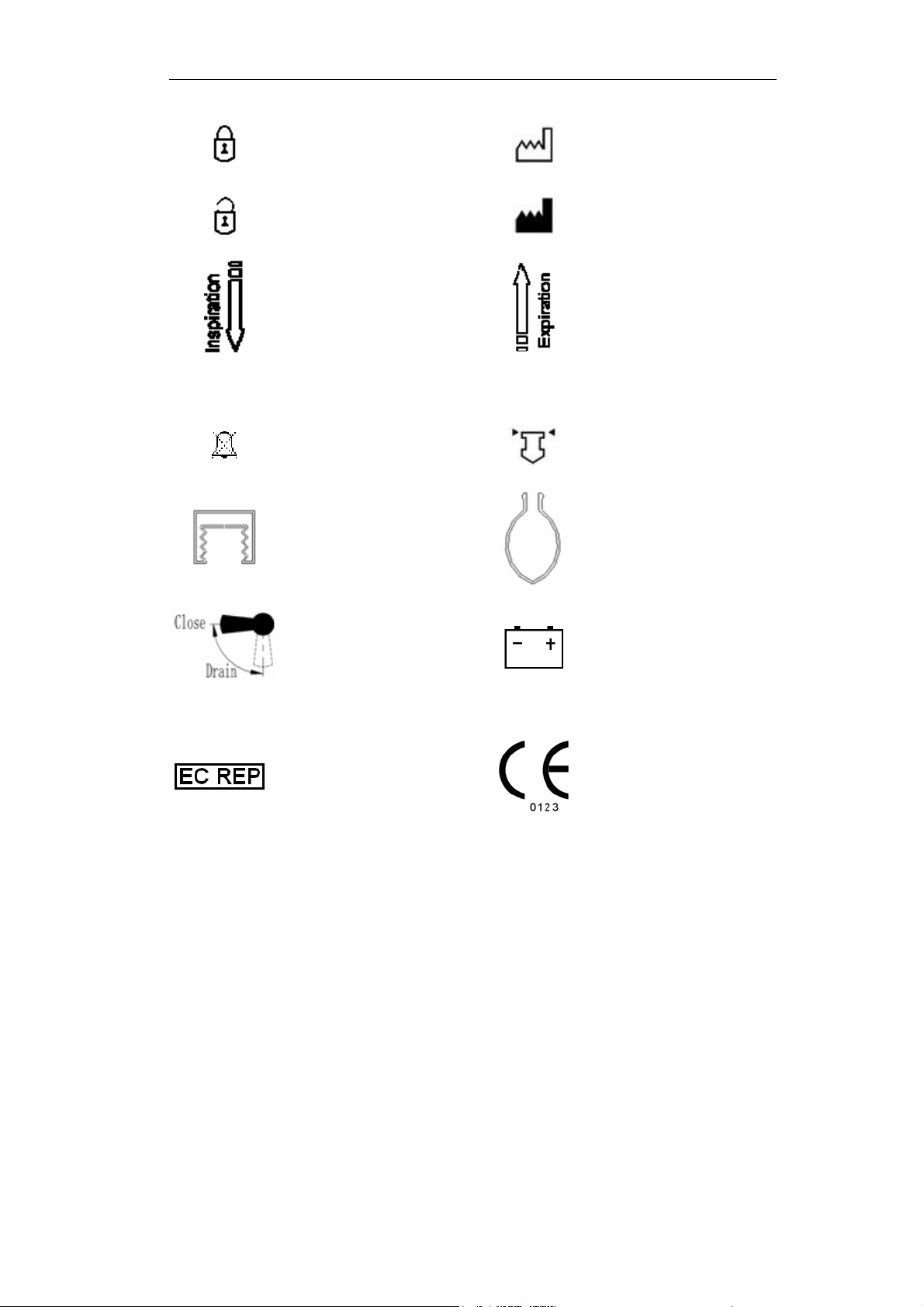
O2+
Lock
Unlock
Inspiration flow
Oxygen flush
Alarm Silence
Ventilator operate Bag operate
SN
Date of manufacture
Address of manufacture
Expiration flow
Serial Number
View the reading on the
top of float
Directions of Drain Valve
CE Representative
Battery
The system, with this
label under the
stipulations in the
operating manual,
complies with the
requirements related
from 93/42/EEC.
1–3
Page 12

Aeon7400A User Manual
1.3 Definition, abbreviation
Not all of the following definition or abbreviation may necessarily appear in the
equipment and manual.
AC100 Code name of Circle Absorber with rotation handle
AC110 Code name of Circle Absorber with pulling handle
AGSS Anesthetic gas scavenging transfer & receiving system
APL Adjustable Pressure Limit
BA100 Code name of bellows for adult use
BA150 Code name of bellows for pediatric use
C Compliance
CGO Common Gas Outlet
f Breath frequency
FiO2 Oxygen concentration
Flow-t Flow-time waveform
I:E Inspiration to expiration time
IPPV Intermittent positive pressure ventilation
Manual Manual ventilation
MV Minute volume
Paw Pressure of airway
P
Peak pressure
peak
P
Plat pressure
plat
Paw-t Pressure-time waveform
V-t Tidal volume-time waveform
F-t Flow-Time waveform
VT Tidal volume
VTI Inspiratory tidal volume
VTE Expiratory tidal volume
1–4
Page 13

2 Anesthetic System Control
2.1 Anesthetic system
CAUTION: The anesthetic system is intended to be used with the
following monitoring devices, alarm systems, and
protection devices:
-- pressure measuring in accordance with 8.1 of ISO 8835-2;
-- pressure limitation device in accordance with 51.101.1 of
IEC60601-2-13;
-- exhaled volume monitor in accordance with 51.101.4 of
IEC60601-2-13;
-- breathing system integrity alarm system in accordance
with 51.101.5 of IEC60601-2-13;
-- continuing pressure alarm in accordance with 51.101.6 of
IEC60601-2-13;
monitor in accordance with ISO 7767.
-- O
2
WARNING: To avoid explosion hazards, flammable anesthetic agents
such as ether and cyclopropane shall not be used in this
anesthetic workstation. Only anesthetic agents which
comply with the requirements for non-flammable
anesthetic agents as specified in this manual.
Halothane, Desflurane, Sevoflurane, Enflurane, and
Isoflurane have been found to be non-flammable agents.
WARNING: Independent means of ventilation (e.g. a self-inflating
manually powered resuscitator with mask) should be
available whenever the anesthetic system is in use.
WARNING: Do not use antistatic or electrically-conductive breathing
tubes and mask.
WARNING: Leakage and douse of liquid, such as anesthetic agent,
bring on dangerous states or malfunctions inside device.
2–1
Page 14
Aeon7400A User Manual
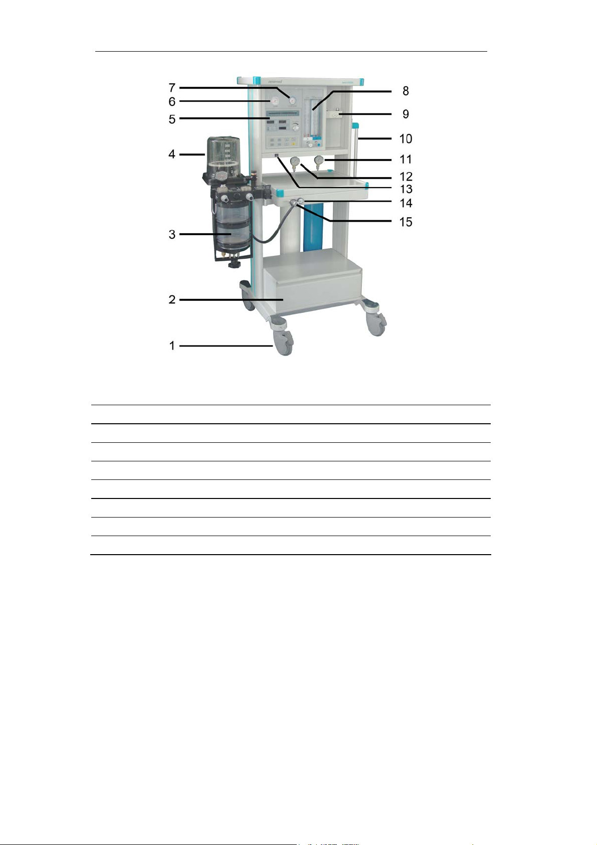
Figure 2-1 Aeon7400A front view (European version)
Legend:
1 Castor 2 Drawer
3 AC100 4 BA100
5 MV200B 6 O2 pipeline pressure gauge
7 N2O pipeline pressure gauge 8 Flowmeters
9 Manifold valve 10 Handle
11 N2O cylinder pressure gauge* 12 O2 cylinder pressure gauge*
13 Power switch 14 Oxygen Flush
15 CGO
*Cylinder pressure gauges are available when Aeon7400A equipped with gas
cylinders.
2–2
Page 15
2 Anesthetic System Control
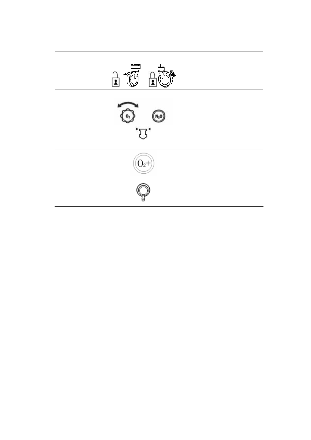
Figure 2-1 each control function on the front view of Aeon 7400A
Item Diagram Description
Castor(with
1
break)
8 Flow Control
Oxygen
14
Flush
15 CGO
Push down to lock, and pull up
to unlock.
Turn the knob counterclockwise
to increase the flow; turn
clockwise to decrease the flow.
Read top of float when the
flowmeter is being read.
Press Oxygen Flush button to
supply O
system with high flow rate
to the breathing
2
Connects the anesthesia
machine to the breathing
system
2–3
Page 16
Aeon7400A User Manual
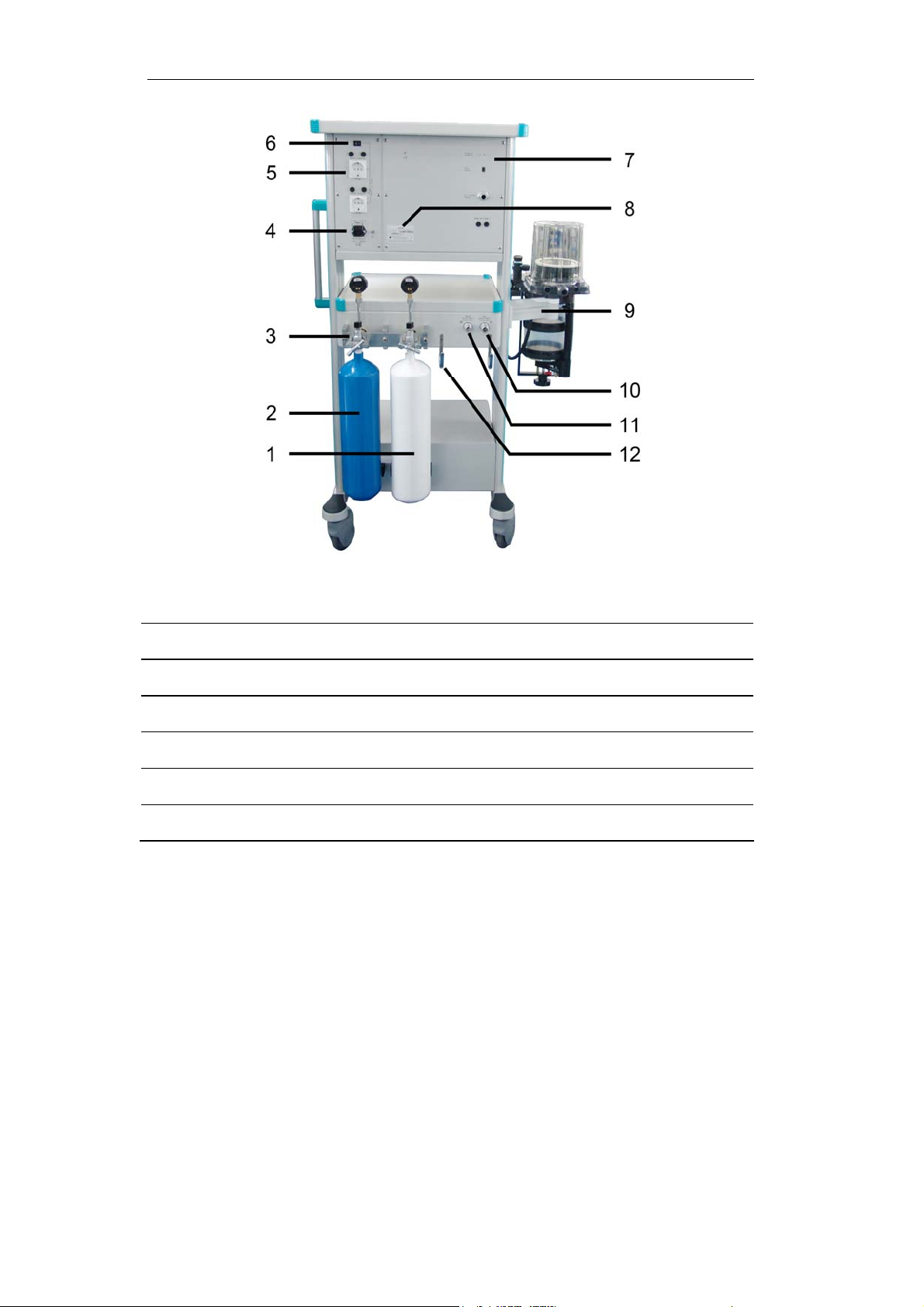
Figure 2-2 Aeon 7400A back view (European version)
Legend:
cylinder (optional) 2 N2O cylinder (optional)
1 O
2
3 Yoke system (optional) 4 Power socket
5 AMSO 6 Auxiliary mains switch
7 Rear panel of MV200B 8 Nameplate
9 Support arm 10 O2 pipeline inlet
11 N2O pipeline inlet 12 Hook
2–4
Page 17
2 Anesthetic System Control
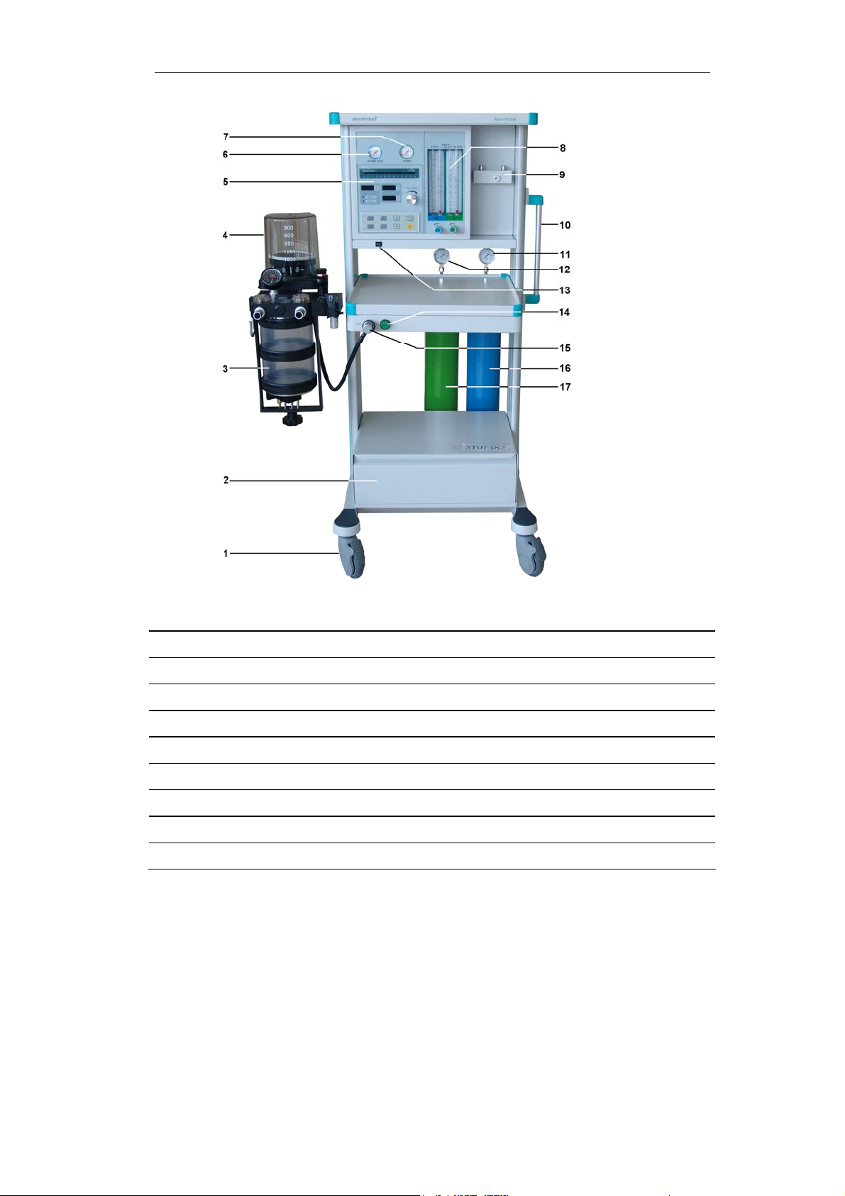
Figure 2-3 Aeon7400A front view (USA version)
Legend:
1 Castor 2 Drawer
3 AC100 4 BA100
5 MV200B 6 N2O pipeline pressure gauge
7 O2 pipeline pressure gauge 8 Flowmeters
9 Manifold valve 10 Handle
11 N2O cylinder pressure gauge* 12 O2 cylinder pressure gauge*
13 Power switch 14 Oxygen Flush
15 CGO 16 N2O cylinder (optional)
17 O2 cylinder (optional)
*Cylinder pressure gauges are available when Aeon7400A equipped with gas
cylinders.
2–5
Page 18
Aeon7400A User Manual
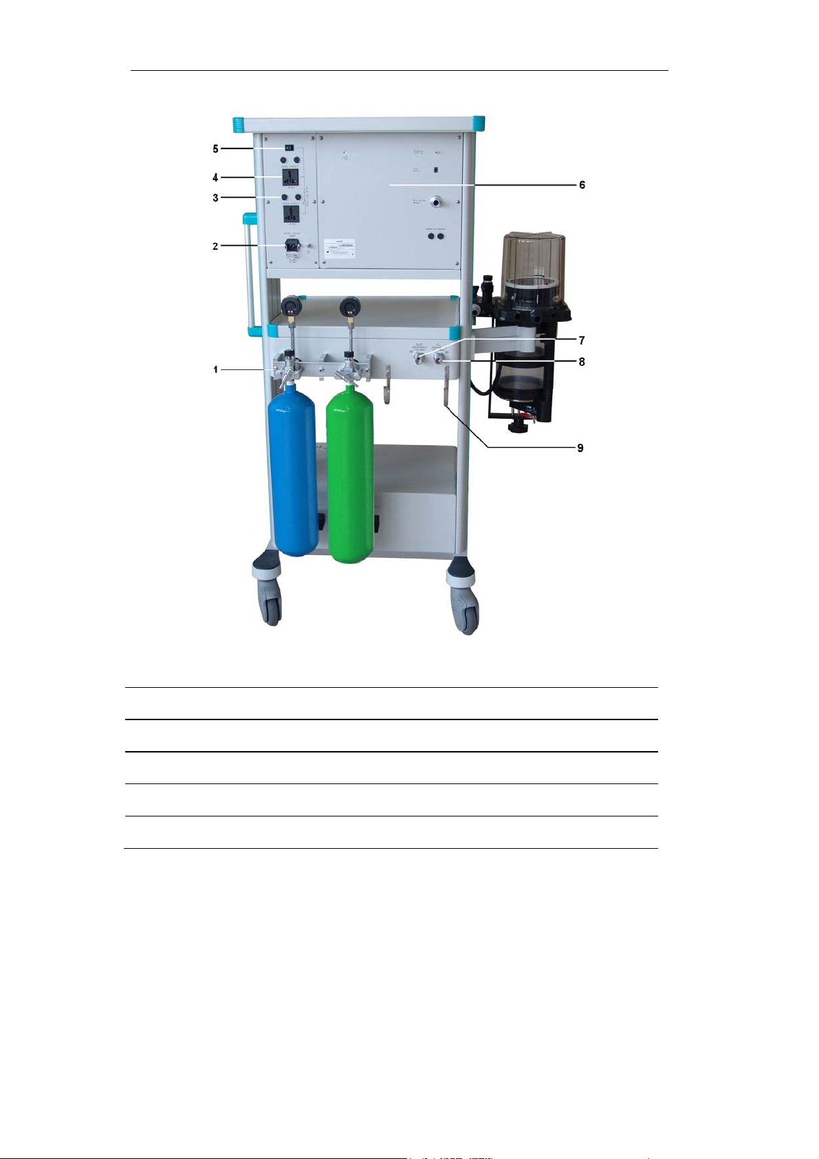
Figure 2-4 Aeon 7400A back view (USA version)
Legend:
1 Yoke system (optional) 2 Power socket
3 Fuse 4 AMSO
5 Auxiliary mains switch 6 Rear panel of MV200B
7 N2O pipeline inlet 8 O2 pipeline inlet
9 Hook
2–6
Page 19
2 Anesthetic System Control
2.2 The Breathing system module
CAUTION: Any adult anesthetic ventilator system used together
with the anesthetic gas supply system must be in
accordance with ISO 8835-2.
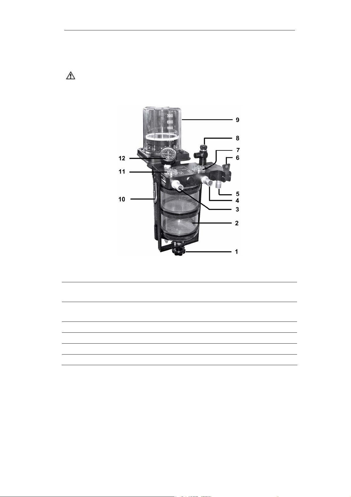
Figure 2-5 Breathing system module
Legend:
1 Absorber mount release handle 2 Absorber
(Carbon dioxide absorbent)
3 Expiratory Port
(Patient circuit connector)
5 Manual reservoir bag port 6 Bag / Ventilator switch
7 Inspiratory valve 8 APL valve
9 Bellows assembly (IPPV ventilation) 10 Hook
11 Expiratory valve 12 Airway pressure gauge
4 Inspiratory Port
(Patient circuit connector)
2–7
Page 20
Aeon7400A User Manual
Figure 2-5 the breathing system components function control
Item Description
Two soda lime canisters are applied with a volume of 1500mL
Absorber
1
mount release
for each so that it can be continuously used for 6 to 8 hours at
full load. The water from the reaction is drained via the water
collector underneath.
IPPV ventilation “off”:
(gas into reservoir bag)
Bag / Ventilator
6
switch
IPPV ventilation “on”:
(gas into bellows)
8 APL valve
Select manual ventilation (reservoir bag) or IPPV ventilation
(ventilator).
Adjust the pressure limit of the breathing system during the
manual ventilation process. The readings are approximate.
The colors represent different pressure zones. Green
represents safety zone; yellow represents transition zone; red
represents high pressure zone. Adjusting ranges between
0.19-6kPa.
2–8
Page 21
2 Anesthetic System Control
2.2.1 Bellows assembly Ports
Figure 2-6 Ports of bellows assembly
1 Breathing system connector 2 Exhaust gas port 3 Driving gas connector 4 Adapter
WARNING: Never connect exhaust gas port with sub-atmospheric
system directly. Or else leakage of breathing system
generates.
The adapter can be used to connect the waste gas scavenging system to the
bellows assembly if the standard pipeline is used in the waste gas scavenging
system.
2–9
Page 22
Aeon7400A User Manual
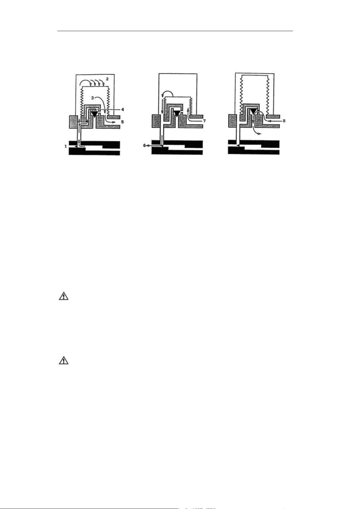
2.2.2 Ventilating circulation
Inhalation primary
phase:
1 Exhalation valve
2 Driving gas
3 Gas of patient circuit
4 Pressure-relief valve
5 To patient circuit
Exhalation primary
phase:
6 Driving gas
7 From patient circuit
Exhalation end phase:
8 Excess gas of patient
circuit
2.3 Vaporizer Control
Refer to operating and maintenance manual of vaporizer for more details.
WARNING: Anesthetic vapor delivery device used with anesthetic
system must be in accordance with ISO 8835-4.
2.4 Ventilator Control
CAUTION: Anesthetic ventilator accords with ISO 8835-5.
2–10
Page 23
2 Anesthetic System Control
CAUTION: Monitoring conditions of this system: Ambient
temperature: 29 ;℃
Air temperature: 30 ;℃ Air humidity: 30%; Gas component:
Oxygen.
CAUTION: If the temperature of sensor is lower than dew point of
breathing gas, vapor may coagulate on the surface of
sensor, and oxygen concentration monitored may be
lower than practice value.
CAUTION: If the temperature of sensor is lower than dew point of
breathing gas, vapor may coagulate on the surface of
sensor, and tidal volume monitored may be lower than
practice value.
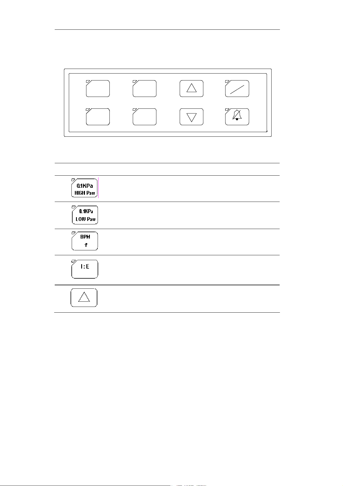
2.4.1 Front Panel
Front panel consists of display screen, keys, indicators, and a knob.
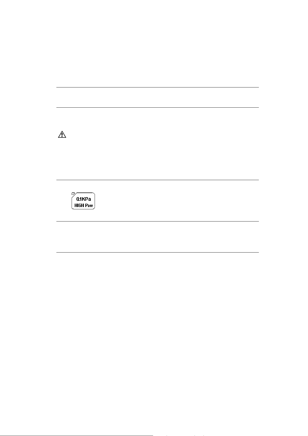
Airway press ure
aw
High P
aw
Low P
0.1kPa
HIG H PRES SURE
0.1kPa
LOW PRESSURE
mL
V
T
BPM
f
I:E
bpm
f
I:E
X0.1kPa
Tidal volume
MANUAL
IPPV
2min
Figure 2-7 Front Panel
2–11
Page 24
Aeon7400A User Manual
2.4.1.1 Control part
0.1kPa
HIGH PRE SSURE
LOW PRE SSURE
BPM
f
I:E0.1kPa
MANUAL
IPPV
2min
Figure 2-8 Control Part
Items Function
High airway pressure limit setting key.
Low airway pressure limit setting key.
Respiratory frequency setting key ranging from six to sixty
bpm.
2–12
Inspiration and respiratory ratio setting key, totally six
positions:
1:4, 1:3, 1:2, 2:3, 1:1, 2:1.
Increase each parameter’s value on screen. (Increasing key)
Page 25
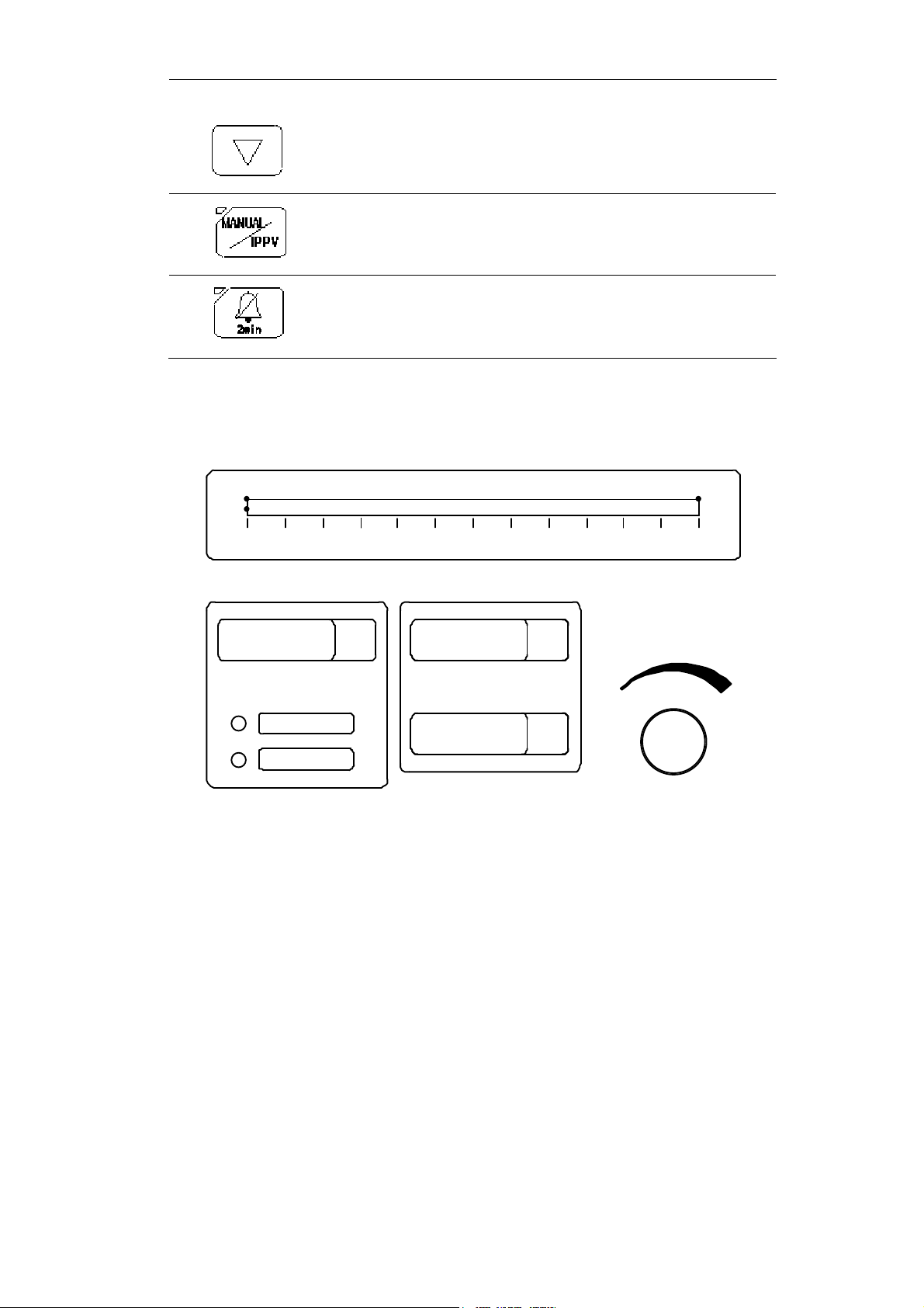
Decrease each parameter’s value on screen. (Decreasing
key)
Manual/IPPV change switch
Eliminate alarm. When alarming, press the key to eliminate
alarm.
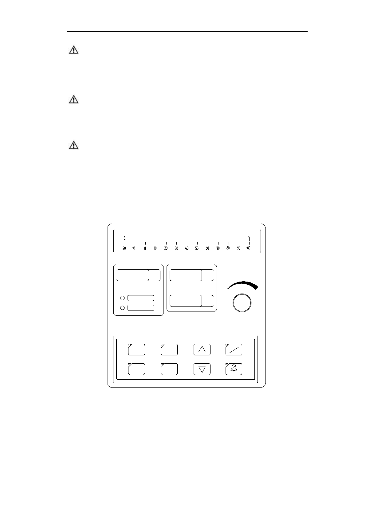
2.4.1.2 Display Screen
2 Anesthetic System Control
Airway pressure
-10-20
High P
Low P
O
aw
aw
30
40
2010
mL
V
T
Figure 2-9 Display Screen
X0.1kPa
60
50
bpm
f
I:E
9070 80 100
Tidal volume
2–13
Page 26
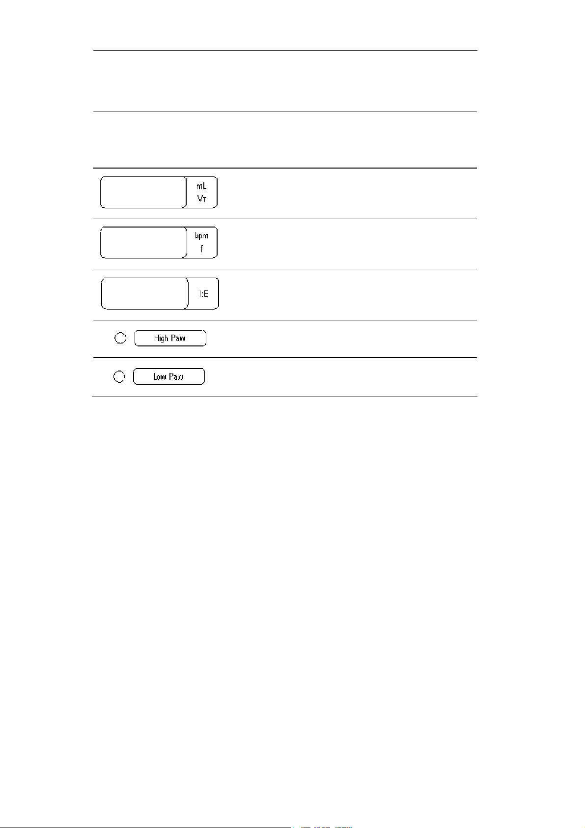
Aeon7400A User Manual
Display symbol’s
implication
Airway pressure
Function
Airway pressure display
Reflect the airway pressure change when patients
respiration.
Display the tidal volume value.
Display Respiratory frequency.
Display Inspiration and respiratory ratio.
Alarm indicator for High Paw.
Alarm indicator for Low Paw.
2–14
Page 27
2 Anesthetic System Control
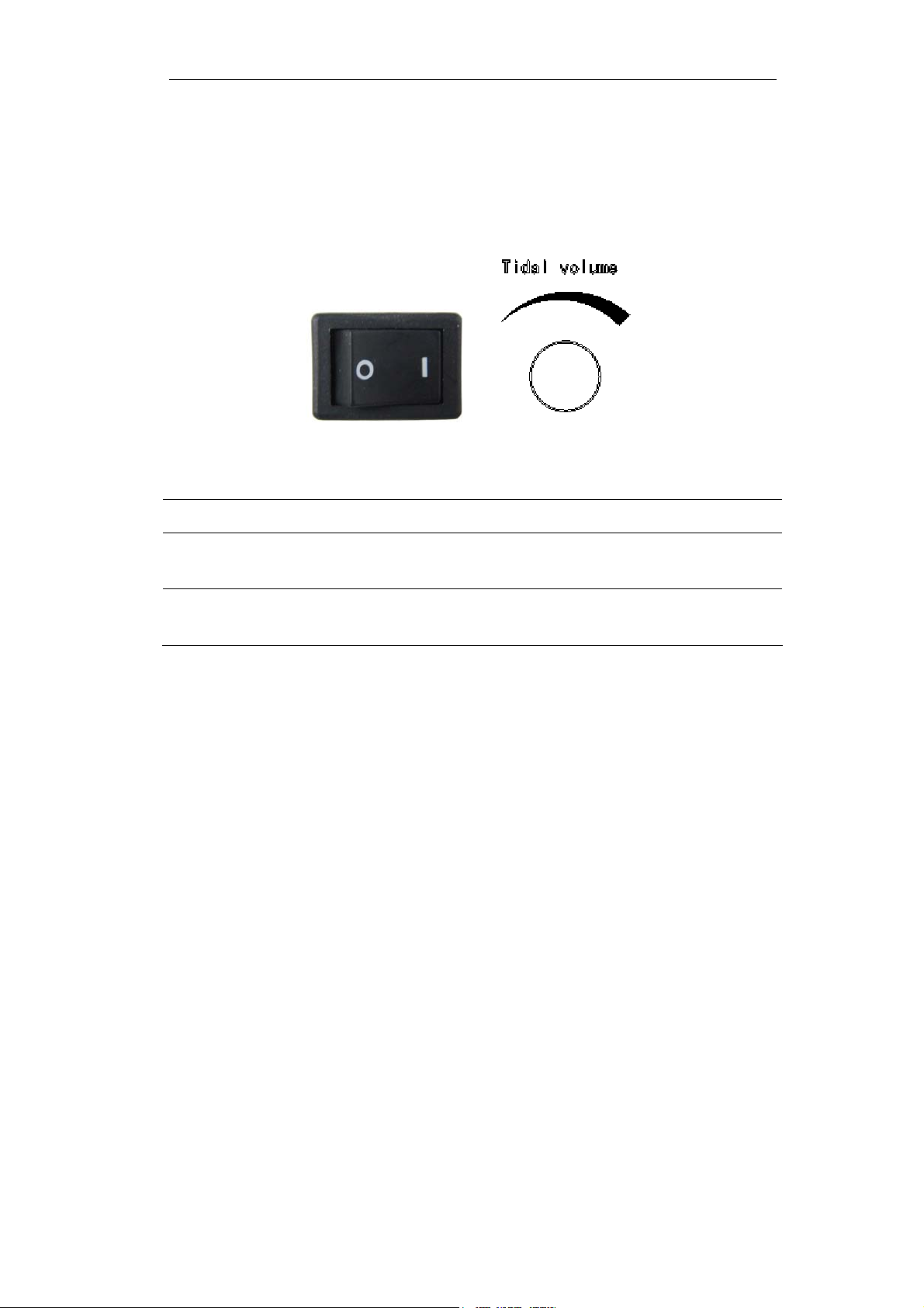
2.4.1.3 Others
The nether picture shows the drawings of the power switch and the tidal volume
control knob.
Figure 2-10 Others Part
Items Function
Power switch
Tidal Volume
control knob
“I” is the denotation of "switch on", and the “O” is the denotation of
"switch off".
Using for inspiratory V
. Turn the knob clockwise to enlarge the VT.
T
2–15
Page 28
Aeon7400A User Manual
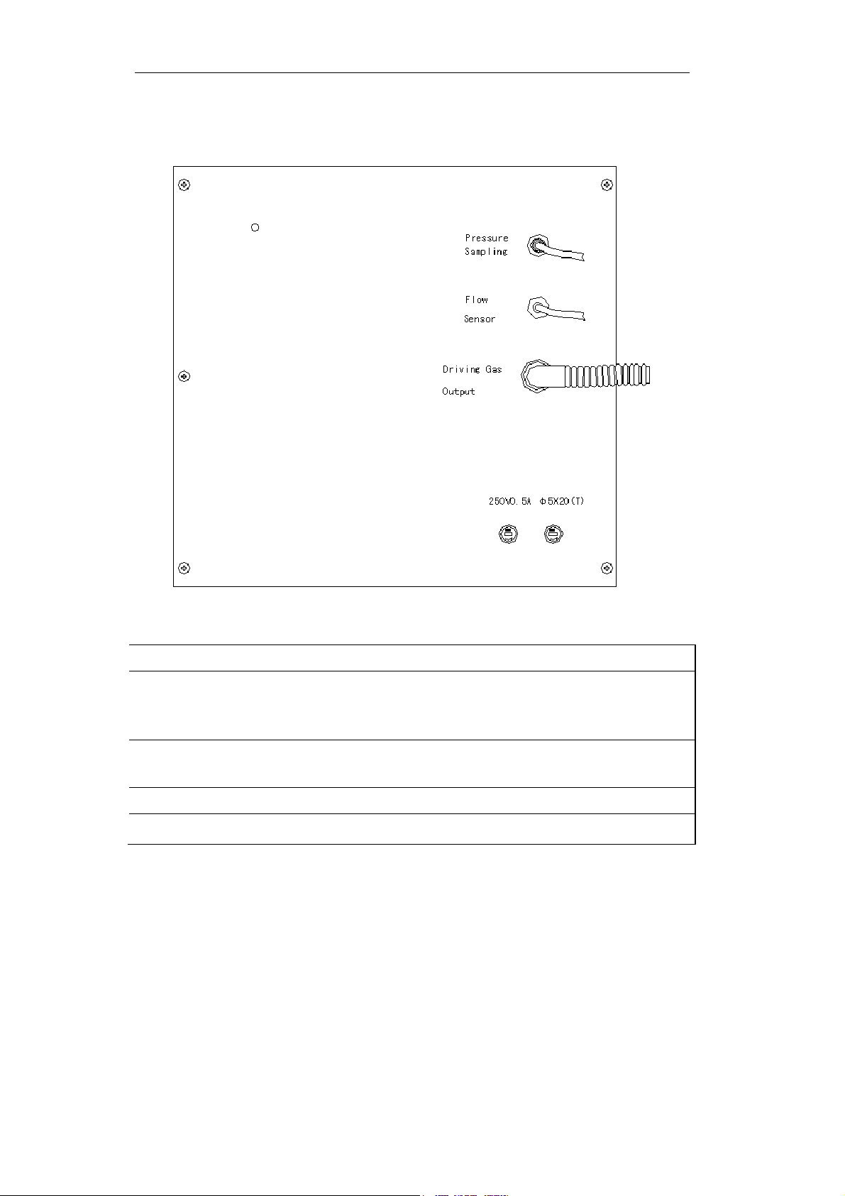
2.4.2 Rear Panel
Figure 2-11 Rear Panel
Legend:
Items Function
Pressure Sampling: Gather Paw by pressure sampling port and then
transfer them to the system at real time to offer gist for
system's monitor and trouble judgment.
Flow Sensor: The monitor of VT is gained from the flow, which was
gathered by the Flow Sensor.
Driving Gas Output: Offer driving gas to drive bellows.
Fuse: Please refer to section 10.3
2–16
Page 29
3 Operating Guide
3.1 Starting System
Step 1: Connect power supply
Plug the power cord into AC power outlet.
Step 2: Power-on
Set power switch to ON (“I”).
WARNING If any unusual malfunction appears, change bag /
ventilator switch to manual mode, stop mechanical
ventilating.
3.1.1 Alarm Limit Set
Step 1
Press , the indicator light on the top left corner will be lighten and this
shows the upper limit of Paw can be reset now.
Step 2
Pressing the keys of or, the position of the red light on the right side of the Paw
display tube will be changed which shows the upper limit of the Paw has been reset.
Reset of the lower limit of Paw is the same.
3–1
Page 30

Aeon7400A User Manual
3.1.2 Ventilator Control Set
Press
press or to reset the RATE.
Press
press or to reset the RATIO.
, the indicator light on the top left corner will be lighten and then
, the indicator light on the top left corner will be lighten and then
3–2
Page 31

3 Operating Guide
3.2 Starting IPPV Ventilation
WARNING: Before getting started, make sure to set the patient
circuit installing and controlling correctly.
The following procedures assume that the system is in
on position and manual reservoir gas ventilating mode.
Step 1
Make sure the control settings according with the clinical settings.
Step 2
Set the reservoir bag / ventilator switch
to ventilator position.
IPPV ventilation ON (gas goes to the
bellow)
Step 3
Press key to make the light on the top left corner dark. That means had
selected the IPPV ventilation mode.
Step 4
Fill the bellows with O
flush if necessary.
2
3–3
Page 32

Aeon7400A User Manual
3.3 Starting Manual Ventilation
Step 1
Before stopping the IPPV ventilation,
make sure the setting of manual circuit
is complete, and the setting of APL
valve is correct.
This valve is used to adjust the
pressure limit of the breathing system
during the manual ventilation period.
Step 2
Pressing the Manual/IPPV key, stop
IPPV ventilation (ventilator).
Set the reservoir bag / ventilation switch
to reservoir bag position, you can use
manual mode ventilation.
CAUTION: Take the monitoring reading of the anesthetic ventilator
rather than the observed reading of the bellows.
OFF (gas goes to the reservoir bag)
IPPV ventilation
3–4
Page 33

4 Preoperative Checkout
4.1 Preoperative Checkout procedures
Test interval Preoperative Checkout should be done in the following situation:
Before the first patient’s use everyday.
Before every patient’s use.
Perform the programs according to requirements after repair or
maintenance.
Test schedule is given in the table below:
Before use of the first patient each day Before use of each patient
System check:
Power failure alarm test:
Gas pipeline and gas cylinder test:
Flow control test:
Vaporizer installation and test
Alarm test:
Breathing system test:
Ventilator test:
Breathing system test:
Ventilator test:
4–1
Page 34

Aeon7400A User Manual
WARNING: Do not use this system before the operation and
maintenance manual are read and understood.
Whole system connection
All warnings and cautions
Using guide of each system module
Testing method of each system module
Before using this system:
Complete all tests of this section
Test all the rest of system modules
If test failure, do not use this system. Please contact service representative.
4–2
Page 35

4 Preoperative Checkout
4.1.1 System Checkout
WARNING: Make sure the breathing circuit is connected correctly
and in good condition.
Make sure:
1 Equipment is in good condition.
2 All the components are correctly connected.
3 Breathing circuit is correctly connected and in good condition; there is
sufficient absorbent in the breathing system.
4 Vaporizer is in lock position and is filled with sufficient anesthetic.
5 The connection and pressure of pipeline gas supply system are correct.
6 The connected cylinder valve should be closed if there are backup
cylinders.
WARNING: Do not leave the cylinder valves open during pipeline gas
supply period; otherwise, cylinder gas supply will be
used up and lead to insufficient supply in case of pipeline
malfunction.
7. The required emergency device is ready and in good condition.
8. The device for airway maintenance, organ cannula are ready and in good
condition.
9. The applicable anesthetic and emergency medicine are ready.
10. Make sure the truckles are tight and locked and free of motion.
Connect the power cord to the AC power outlet.
4–3
Page 36

Aeon7400A User Manual
4.1.2 Mains failure alarm test
1 Turn power switch to “I”. .
2 After operating 5 minutes, pull out power cord.
3 Make sure that power off failure alarm sound.
4 Connect power cord again.
5 Make sure the alarm eliminate.
4.2 Testing gas supply pipeline and gas cylinder
CAUTION: A user must confirm that gas supply is connected
correctly; there is no any disconnection, leakage, faulty
connection in gas circuits and pressure indicates
correctly. Stop using and check gas connections if
abnormal.
CAUTION: To prevent from damage:
Open cylinder valve slowly.
Never control the flow with excessive force.
Skip step 2 if the system is not using cylinder gas
supply.
4–4
Page 37

4 Preoperative Checkout
1 Disconnect all pipeline gas supply and close all the cylinder valves.
If the readings of the pipeline pressure gauge and cylinder pressure
gauge are not zero.
Switch on O
supply.
2
Adjust flow control to middle range.
Make sure all the pressure gauges are reset to zero except the O
pressure gauge.
Switch off O
Make sure the O
supply.
2
pressure gauge is reset to zero. The low O2 supply
2
alarm should be on when pressure drops.
2 Make sure cylinders are fully filled:
Open each cylinder valve.
Make sure the pressure of each cylinder is high enough. In case the
pressure is insufficient, close the corresponding cylinder valve and
install a fully filled cylinder.
3 Test cylinder high pressure leak one by one.
4 Close flowmeters.
5 Open the cylinders.
2
6 Record the cylinder pressures.
7 Close the cylinder valves.
8 Begin to record the pressures after one minute. If O
pressure drops to
2
5000kPa, it means there is a leakage:
If leakage exists, according to direction of section 5.5, replace a new
sheet gasket, and then tighten T handle.
Perform this step again. If leakage exists all the same, do not use this
system.
4–5
Page 38

Aeon7400A User Manual
9 Step 5~7 should be repeated for all the cylinders. N
O pressure drop in one
2
minute should not exceed 700kPa.
10 Close all the cylinder valves.
CAUTION: Do not leave the cylinder valves open during pipeline gas
supply period; otherwise, cylinder gas supply will be
used up and lead to insufficient supply in case of pipeline
malfunction.
11 Connect pipeline gas supply.
12 Check pipeline pressure according to the table below:
ANSI (U.S. and International), Australia, Canada,
345kPa (50 psig)
France and Japan
ISO, Italy, Scandinavia, South Africa, Spain and
414kPa (60 psig)
Switzerland
Austria and Germany 500kPa (75 psig)
4–6
Page 39

4 Preoperative Checkout
4.3 Monitoring Flow Control
WARNING: The monitoring system cannot be replaced by link system.
The fresh gas containing enough oxygen may not avoid the
existence of low oxygen mixture in the breathing circuit.
If N2O exists, it will pass through the system during the test,
which should be securely collected and removed.
Patients may be injured by improper gas mixture. The link
system should not be used if a proper ratio of O2 and N2O is
not possible.
The following procedures can test whether the link system
has serious malfunction; however, it cannot determine
whether the calibration is correct.
CAUTION: The gas flow switch should be adjusted slowly. Do not turn
it hard when the reading of the flowmeter goes beyond the
maximum or minimum flow rate; otherwise, the control
valve can be damaged and the control will not work.
Follow the steps to test the flow control:
1. Connect the pipeline gas supply or open the cylinder valves slowly.
2. Turn clockwise all the flow control till the end.
3. Turn on power switch.
4. Make sure:
No gas flowing in any flow tube.
Step 5 and step 6 are only applicable for the N
O system test.
2
4–7
Page 40

Aeon7400A User Manual
WARNING: During Step 5 to Step 6, keep link systems working st ate.
Only adjust testing of control (N2O in step 5 and O2 in
step 6).
Adjust flow according to order (N
If adjustable range exceeds, please adjust flow control to
the nearest place and perform this step again.
5. To test the flow increase of the link system:
Turn clockwise the N
Turn counterclockwise the N
Set N
O flow control to the rate described in the following table. The O2
2
O and O2 flow control till the end.
2
O flow control slowly.
2
flow must be higher than the minimum flow limit.
Set N
O flow to
2
O2 flow must be higher than the minimum
(liters per minute):
1.5 0.5
3.0 1.0
6.0 2.0
9.0 3.0
O firstly O2 secondly).
2
flow
(liters per minute):
7. This step tests the function of the Link System when flow is reduced, you
should:
Set N
(liters per minute):
O flow to
2
O2 flow must be higher than the minimum
flow
(liters per minute):
2.0 6.0
1.0 3.0
0.5 1.5
4–8
Page 41

4 Preoperative Checkout
8. Adjust full flow of all the gas to ensure that the flowmeter float must move
smoothly.
9. Shut off the oxygen supply either by closing the oxygen cylinder valve, or by
disconnecting the oxygen pipeline supply.
10. Make sure:
As pressure decreases, the oxygen-supply failure alarm must continuously
sound.
Disconnect the flow of nitrous oxide and oxygen to be sure that the oxygen
flow will be the last to stop.
If the oxygen is the driving gas of the ventilator, the oxygen-supply failure
alarm must continuously sound.
11. Turn all control valves completely clockwise to the close.
12. Reconnect oxygen pipeline supplies or slowly open the oxygen cylinder valve.
13. Turn off power switch.
4–9
Page 42

Aeon7400A User Manual
4.4 Installing and testing of vaporizer
Please refer to the User Manual of the vaporizer.
4.5 Alarm testing
1. Oxygen Pressure Low Alarm:
Depress the oxygen pressure gradually. The alarm for oxygen pressure low should
occur when the pressure is lower than 0.2MPa.
2. High Paw Alarm:
Regulate VT, make the indication of the peak Paw become 2.5kPa. Then reset the
upper limit of the High Paw alarm, when the value is under 2.5kPa, High Paw alarm
(audible and visual) should occur.
3. Low Paw Alarm:
Reset the upper limit of the Low Paw alarm to 0.1kPa, pick off the tube, and the
audible and visual alarm should occurs after 4~15 seconds.
4.6 Testing the Breathing System
Refer to the operating manual and:
Verify the non-return valve in the Breathing circuit module works normally:
The non-return exhalation valve will ascend during the exhalation period while it will
descend during the inhalation period.
WARNING: Objects in the breathing system can interrupt or disrupt
the delivery of breathing system gas, resulting in
possible patient death or injury:
Do not use any testing plug small enough to slip
completely into the breathing system.
4–10
Page 43

4 Preoperative Checkout
4.6.1 Checking Oxygen flush button
Press the O2+ button (the sound of gas should be heard from the fresh gas outlet)
then release. The button must immediately drop back to its position and stop
delivering the gas.
4.6.2 Testing Breathing System
Set the Bag/Ventilator switch to Bag control. The airway pressure gauge is zeroed.
APL Valve should be rotated fully clockwise to the maximum. Connect corrugated
tubing, Y-piece to the simulation lung.
Connect reservoir bag to the manual reservoir bag port of absorber circle. Press the
O2+ button or open the flowmeter to make the indication of the airway pressure
gauge achieve 3kPa, then release the button and close the flowmeter. After 20
seconds observation, the pressure drop indicated by the airway pressure gauge
must not exceed 0.3kPa.
4.6.3 Testing APL Valve
Adjust the positions of every switch and knob according to the method of testing
Breathing System Leak. Open the O
position the pressure of the pressure gauge in different places respectively. The
common gas outlet must overflow some gas as the pressure is stable.
WARNING: Be sure that there is no any testing plug or foreign
objects in the Breathing
flow to 5L/min. Adjust the APL valve to
2
System.
4–11
Page 44

Aeon7400A User Manual
4.7 Testing Ventilator
1 Connect the simulation lung to the patient end.
2 Set the Bag / Ventilator switch to the bag position.
3 Turn on power switch.
4 Set control options:
Ventilation mode: IPPV mode
Ventilator: VT: 700ml
f: 20bpm
I:E: 1:2
High Paw: 40cmH
Anesthetic machine: O2 flow: less than 200mL
O flow: close
N
2
O
2
5 Set the Bag / Ventilator switch to ventilator control.
6 Press the O
+ button to inflate the bellows.
2
7 Ensure:
IPPV ventilation start.
No low pressure alarm.
Ventilator displays the correct data.
The bellows up and down during IPPV ventilation.
4–12
Page 45

4 Preoperative Checkout
8 Set the O
flow control to 5L/min.
2
9 Ensure:
Ending expiratory pressure is less than 3cmH
2
O.
Ventilator displays the correct data.
The bellows inflate and scavenge during IPPV ventilation.
10 Set the ventilator control and alarm limits to the proper clinical level.
11 Turn off mains supply and close all valves of gas cylinders if not to use the
system.
12 Ensure that the things in the following table should be prepared completely.
Apparatus: Airway maintenance
Manual ventilation
Organ cannula
anesthesia and emergent drugs applicably
13 System preparation:
Close all vaporizers.
Open the APL valve.
Set the bag / ventilator switch to bag control.
Set all the flow controls to the close.
Be sure that the breathing system connects correctly.
4–13
Page 46

Aeon7400A User Manual
WARNING: Be sure that the breathing system connects correctly.
WARNING: Flush the anesthesia m achine for at least one minute by
using O
with 5L/min flow speed to remove unnecessary
2
mixed gas and objects in the system before connecting
the equipment to the patient end.
WARNING: Anesthesia equipment must be connected to the waste
gas scavenging system to outlet the waste gas to
prevent the staff working in the operating rooms from
injury.
This requirement must be followed in the testing and
clinical application.
4–14
Page 47

5 Installing and Connecting
CAUTION: O2 monitoring must be used on this equipment. For the
related stipulations, refer to local standards.
CAUTION: According to the European standard EN 740 and
International Standard IEC 60601-2-13 / ISO 8835-1, this
equipment must use expiratory volume monitoring, O
monitoring (in accordance with EN 12342 or ISO 7767) and
monitoring (in accordance with EN 864 or ISO 9918).
CO
2
CAUTION: Anesthetic monitoring (in accordance w ith ISO 21647:2004)
must be made as the anesthetic vaporizer is being used
according to the European standard EN 740 and
International Standard IEC 60601-2-13 / ISO 8835-1.
2
WARNING: Operating room environment can be influenced by the
expiratory gas. Some unexpected dangers may occur if
the anesthetic has been not tested for a long time. The
operator must dispose of expiratory gas in a timely
fashion according as required, and examine other items
to minimize the chances of danger and malfunction.
WARNING: Be sure the gas pipeline supply hoses and the breathing
circuit components are non-poisonous, do not cause
patient allergy, and do not create dangerous by-product
through reaction with the anesthesia gas or the
anesthetic.
5–1
Page 48

Aeon7400A User Manual
WARNING: To prevent generating wrong data and malfunction,
please use the cables, hoses, and tubes from Aeonmed.
CAUTION: It is dangerous if there is anesthetic in the absorber.
Measures must be made to prevent the soda lime in the
absorber from drying. Turn off all the gas supplies after
finishing using the system.
CAUTION: This system can be operated correctly under IEC 60601-1-2
interference. Higher-level interference may cause alarm
and result in auto ventilation suspension.
CAUTION: To avoid equipment false alarm caused by high strength
electric field:
Put the electricit y surgical conducting wire far from
the place where the breathing system is put on.
Do not put the electricity surgical conducting wire
on any parts of the anesthetic system.
CAUTION: To protect the patient, as the electricity surgical
equipment is being used:
Monitor and ensure that all the life supporting and
monitoring equipment are operated correctly.
Ensure that the backup manual ventilator can be
used immediately in case that electricity surgical
equipment cannot secure the use of ventilator.
Never use electrical conduction masks or hoses.
5–2
Page 49

5 Installing and Connecting
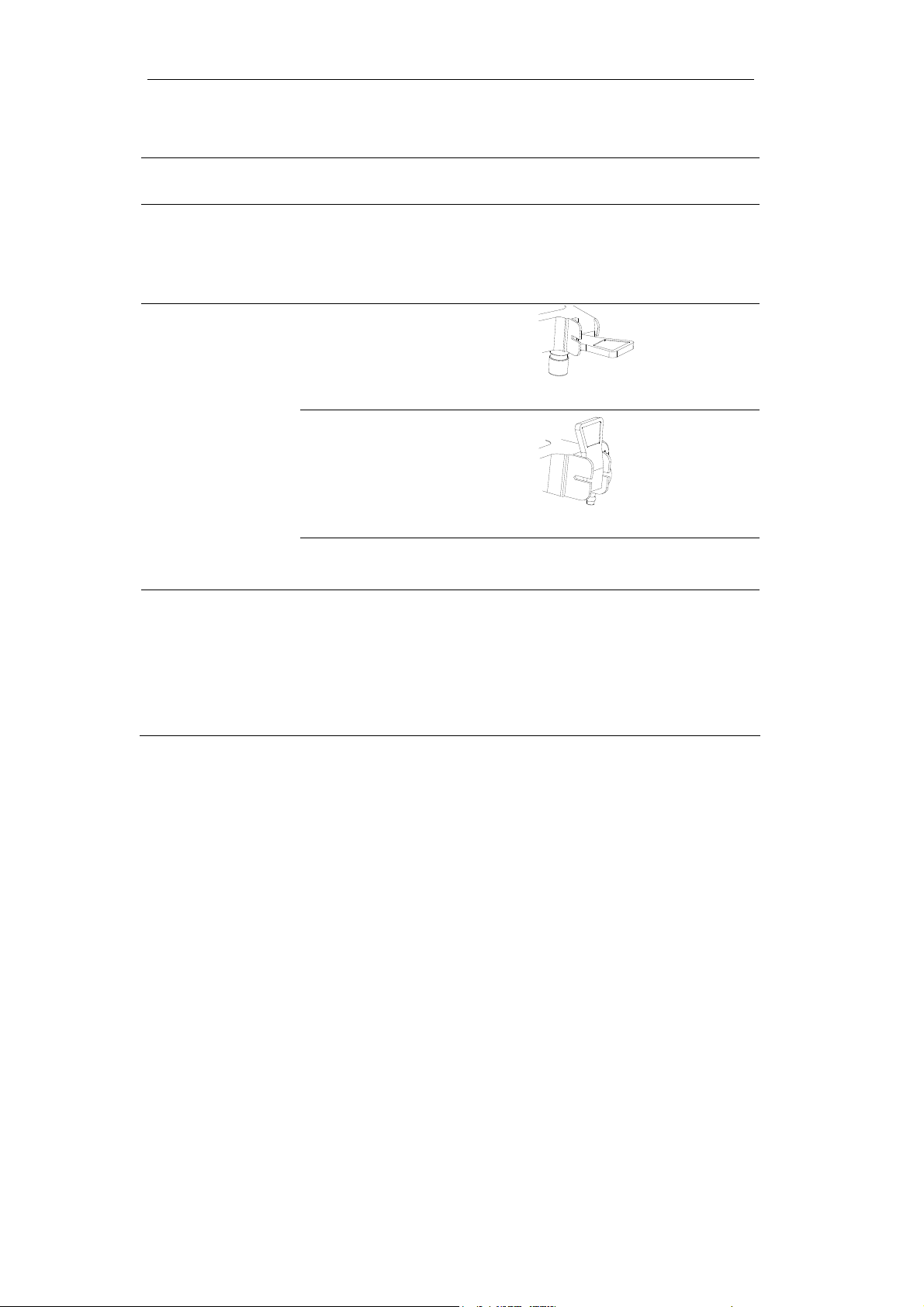
5.1 Installing Product
Step 1
Unpack the bottom package, take out the shelf and lock its castors so it cannot
move freely.
Step 2
Connect the support arm to its mounting
tracks, and then tighten the screws.
Step 3
When installing, hold the top plate of the
breathing circuit with both hands, connect
the position fixing hole to the limb post, sit it
on the limb post,
Then tighten the knob.
5–3
Page 50

Aeon7400A User Manual
Step 4
Connect the mounting plate to the bolt hole
of the absorber cycle, and then tighten the
screws.
Step 5
Place bellows assembly on the mounting
plate, then push the locking clamp.
Tighten the knob below the mounting plate
to fix the bellows assembly.
5–4
Page 51

5 Installing and Connecting
5.2 Installing Absorber
CAUTION: The Aeon7400A shall comply with configurations and
conditions under which clause 24 of the General Standard
IEC 601-1.
WARNING: Follow the proper security measures:
Do not use the absorber if the anesthetic is chloroform or
trichloroethylene.
Avoid the skin or eyes touching the materials in the absorber.
Clean the affected part immediately and seek medical
attention if materials come in contact with skin or eyes.
Do not replace absorber during the period of ventilating.
Replace the absorbent often to prevent the deposition of
non-metabolism gas as the system is not on.
Check the color of the absorbent after finishing each case.
The original color of the absorbent may be restored when not
in use. Refer to the labels of the absorbent for the details.
Carbon monoxide is released if completely dried absorbent
contact with the anesthetic. Replace the absorbent for
security.
Perform leakage tes ting of breathing system in bag control
mode after disassembling the absorber.
The absorber in this system can be used repetitious.
The capacity of each absorber is 1500mL.
Only air, oxygen, carbon monoxide, halothane, enflurane, isoflurane, sevoflurane
and desflurane can be used for the absorber.
5–5
Page 52

Aeon7400A User Manual
5.2.1 When to replace absorbent
Changed color of the soda lime in the absorbent indicates that it has absorbed the
carbon dioxide; however, this color is not 100% accurate. To decide whether to
replace the absorbent, use CO
Remove the changed-color absorbent immediately. The soda lime will restore its
original color several hours later and that may mislead the operator.
monitoring machine.
2
5.2.2 Disassembling Absorber
The absorber is reusable. Follow the disassembling procedures:
1 Turn on drain valve to get rid of
water generated by chemical
reaction.
2 Rotate the handle clockwise to
disassemble the absorber.
3 Tip and take out the absorber.
5–6
Page 53

5 Installing and Connecting
5.2.3 Filling Absorbent
1 Remove the absorbent of absorber.
2 Cleaning and disinfection refer to section 6.3.
3 Fill the absorber with fresh absorbent after dryness. Wipe soda lime fell on the
edge of absorber, and then install it back. Make sure the airtightness is well,
and that no leakage and spillage.
5.3 Connecting tubes and lines
CAUTION: CO2 monitor (in accordance with ISO 9918) should be
connected at L-piece of patient end.
CAUTION: Anesthetic agent monitor (in accordance with ISO
21647:2004) should be connected at T-piece installed
inspiratory port..
CAUTION When connect tubes, the junction should be close and
tight.
Step 1
Connect the common gas outlet and the fresh
gas inlet with pipe, and then screw down the
cap to fix.
CAUTION:
This step had batter be finished before
installing the bellows.
5–7
Page 54

Aeon7400A User Manual
Step 2
Connect bellows with absorber circuit using a
corrugated tubing (Ф22).
Step 3
Connect bellows with inspiratory port on the rear
panel of the ventilator using a corrugated tubing
(Ф17).
Step 4
Connect the pressure sampling T-piece on to
the Inhalation port. Then connect one end of the
pressure sampling pipe onto the T-piece.
The other end of the pressure sampling pipe
was connected onto the pressure sampling port
on the rear panel.
5–8
Page 55

Step 5
Connect the flow sensor subassembly.
First connect turbine sensor onto the
exhalation port.
White probe was chucked onto the
turbine sensor.
The other end of the cable conductor
was connected onto the flow sensor port
at the rear panel.
5 Installing and Connecting
5–9
Page 56

Aeon7400A User Manual
Step 6
Connect the breathing tubes.
Connect the two corrugated tubing onto
inhalation and exhalation ports
respectively.
The other ends of the two tubes were
connected with Y-piece and L-piece,
then mask. Note: if the breathing tubes
is design for one use, the two tubes and
the Y-piece are incorporated.
Step 7
The connection of the Manual
subassembly:
First connect the short corrugated tubing
with the Manual reservoir bag port. Then
connect the adapter with the corrugated
tubing and last connect the manual
reservoir bag with the adapter.
5–10
Page 57

5 Installing and Connecting
5.4 Connecting Gas and Electricity
WARNING: IEC 60601-1-1 applies both for combination of items of
medical electrical equipment and for combinations of at
least one item of medical electrical equipment with one
or more items of non-medical electrical equipment. Even
if there is no functional connection between the
individual pieces of equipment, when they are connected
to an auxiliary mains socket outlet they constitute a
medical electrical system. It is essential that operators
are aware of the risks of increased leakage currents
when equipment is connected to an auxiliary mains
socket outlet.
WARNING: The equipment connected to the power outlet will
increase electric current leakage. Test electric current
leakage regularly.
WARNING: A malfunction of the central gas supply system may
cause more than one or even all devices connected to it
to stop their operation simultaneously.
CAUTION: Disconnect the anesthetic workstation from the gas
supply after use to prevent contamination or pollution of
the pipeline system.
CAUTION: Only the medical gas supply should be used. Other
types of gas supply may
pollutants.
WARNING: All connectors of gas supply have different dimensions
and structures. It can avoid wrong operation occurs.
contain water, oil or other
5–11
Page 58

Aeon7400A User Manual
5.4.1 AC inlet
AC Power:
100 to 240VAC, 50/60Hz; 5A Max.
Fuse:
250V/5A, Ф5X20(F)
Clasp can stop power cord breaking off.
5–12
Page 59

5 Installing and Connecting
5.4.2 Auxiliary mains socket outlet
CAUTION Auxiliary mains socket outlets operator-accessible
should be not more than four when in use Aeon7400A.
This label displays the voltage of the power supply and the rated ampere value of
the circuit breaker.
Fuse: 250V 2A, Ф5X20 (F)
Maximum current outlet: 1.5A (each); 3A (total)
5–13
Page 60

Aeon7400A User Manual
5.4.3 Pipeline gas supply inlet
Pressure inlet: 280 to 600kPa
Pipeline
connector:
DISS (Diameter-indexed safety system).
It can prevent wrong connection generating.
5.4.4 Cylinder gas supply inlet
Cylinder
connector:
WARNING: The connecting procedures of O2 and N2O to the rear of
PISS (Pin-indexed safety system)
It can prevent wrong connection generating.
the anesthesia system have been provided. Each has a
different dimension to avoid wrong connection. A
continuous pressure monitoring device is installed in the
front of the anesthesia system to monitor each gas that
connects with hospital supply pipelines.
5–14
Page 61

5 Installing and Connecting
5.5 Install gas cylinder (Test high pressure leak)
CAUTION: Do not turn the cylinder valve on w hen the pipeline gas
supply is being used. The gas supply of the cylinder may
be used out in case of pipeline failure so that the backup
supply may be insufficient.
1 Turn the handle T of the cylinder valve clockwise until it is tight. Close the valve
of the cylinder to be changed.
2 Release the yoke piece, then disassemble the cylinder.
3 Remove the valve cap from the new cylinder.
4 Keep the cylinder inlet away from all the objects which could be damaged by
the release of high pressure gas.
5 To clear the cylinder valve of any debris, use the cylinder wrench to briefly open,
then close the cylinder.
6 Install the cylinder.
Align index pin with the basic hole of the gas cylinder.
Close yoke piece and screw handle T.
5–15
Page 62

Aeon7400A User Manual
7 Perform the high pressure leak test:
Disconnect the pipeline gas supply.
Close flowmeter.
Open the cylinder.
Close the cylinder.
Record the pressure of the cylinder.
If the pressure of the O
cylinder drops more than 5000 KPa after one
2
minute, the high pressure circuit has an unacceptable leak.
If the pressure of the N
O cylinder drops more than 690 KPa after one
2
minute, the high pressure circuit has an unacceptable leak.
Repairing gas leak
Install a fresh cylinder gasket and tighten the connector.
Repeat this step. Do not use this system in case of continuous gas leak.
5–16
Page 63

5 Installing and Connecting
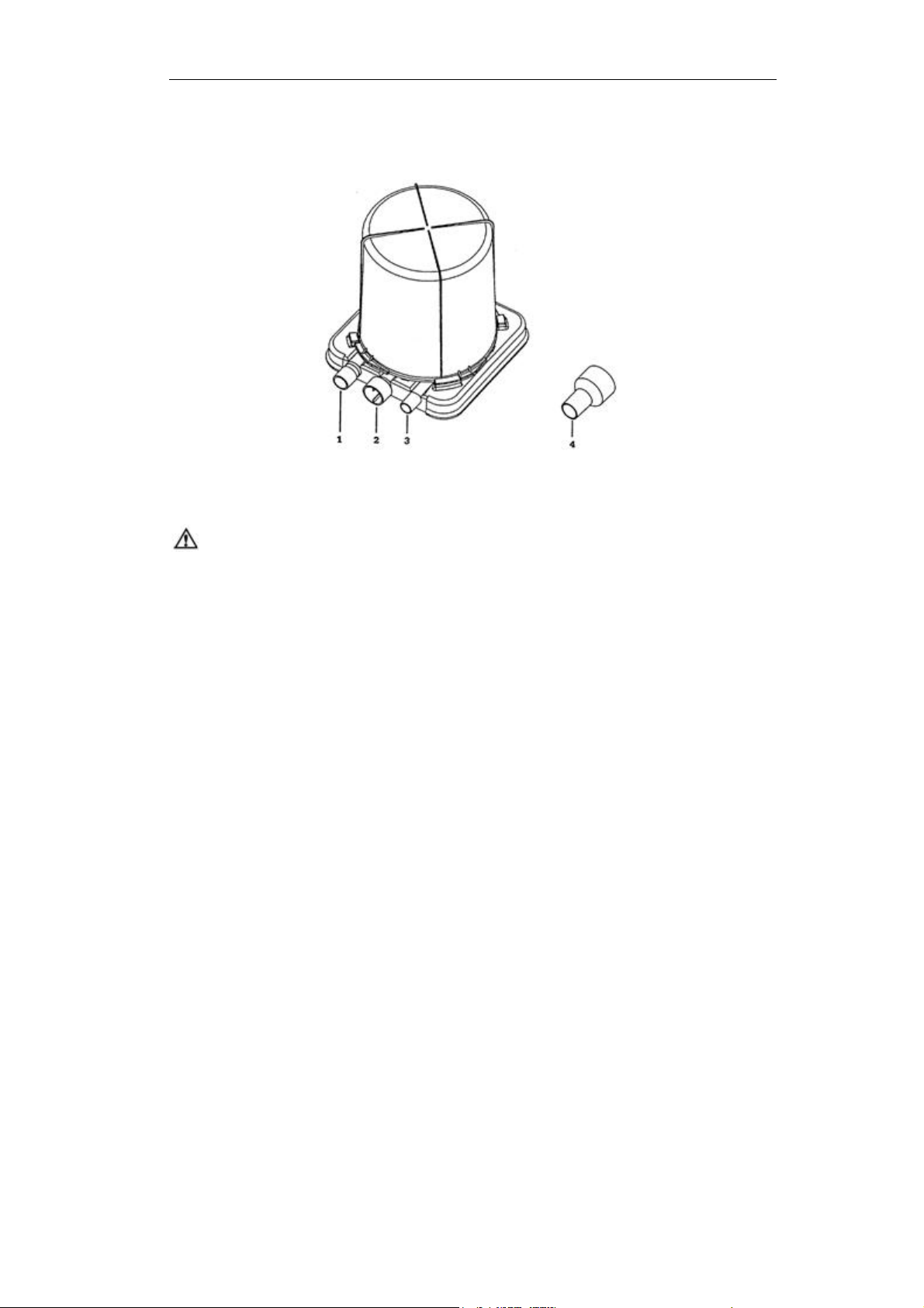
5.6 Connect to AGSS
There are two ports releasing exhaust gas in this system. Connect the two ports to
gas scavenging transfer and receiving system with tubes.
1. APL valve
2. Exhausting port of bellows assembly
See the following figure; number 2 is the exhausting port..
5–17
Page 64

Aeon7400A User Manual
5–18
Page 65

6 Cleaning and Disinfecting
WARNING: Use a cleaning and disinfecting schedule that conforms
to your institution’s disinfection and risk-management
policies.
Refer to the material safety data policy of each agent.
Refer to the operating and maintaining manual of all the
disinfecting equipments.
Do not inhale fume.
CAUTION: To prevent damage:
Refer to the data supplied by the manufacturer if there are
any questions about the agent.
Never use any organic, halogenate or oil base solvent,
anesthetic, glass agent, acestone or other irritant agents.
Never use any abrasive agent to clean any of the
components (i.e. Steel wool, silver polish or agent).
Keep liquids far from the electrical components.
Prevent liquid from entering the equipment.
Do not immerse the s ynthetic rubber components more than
15 minutes: any longer will cause inflation, or accelerating
aging.
Only the components marked 134℃ are pressure-resistant
and heat-resistant.
The PH value of the cleaning solution must be from 7.0 to
10.5.
6–1
Page 66

Aeon7400A User Manual
WARNING: Talc, zinc stearate, calcium carbonate, or corn starch that
has been used to prevent tackiness could contaminate a
patient’s lung or esophagus, causing injury.
CAUTION: Never immerse the flow sensor in the liquid.
Do not clean the inner surface of the flow sensor. Clean the
outer surface by using a damp cloth.
Check if there is damage in the components. Replace if
necessary.
6.1 Cleaning and disinfection of pre-use first
Main unit
Breathing system
components
Absorber cycle Washing, refer to section 6.4
Bellows assembly Washing refer to section 6.5.4
Clean the machine’s panel and all surfaces with soft cloth
soaked with the water soluble disinfecting agent.
Sterilize main unit with ultraviolet radiation. Do not use
acetic hyctro peroxide or formaldehyde steaming.
Refer to section 6.2
6–2
Page 67

6 Cleaning and Disinfecting
6.2 Cleanable Breathing System Components
Corrugated tubing (contacted
with patient), face mask, Y-piece
connector, L-piece, reservoir bag
Corrugated tubing and bag
(repetitious)
T-piece Washing to sterilize
Pressure sampling pipe Clean with soap before use of each patient, and
Components marked 134℃ are pressure-resistant and heat-resistant and can be
cleaned by hand or by machine (by using the mild agent with PH < 10.5). Scrub
them thoroughly, then air out to dry.
Clean the bellows assembly by disassembling them, or they will take longer to dry.
To dry, hang the bellows by from its top disk while spread fully. Moisture remaining in
the folds of the bellows may make the bellows tacky.
Designed for using only once, not need to
sterilize.
The waste should be recovered.
When to replace these expendable, products
with medical level and equal specification
should be selected to use.
Washing to sterilize
then washing in disinfecting solution after airing.
Reassemble the bellows assembly prior to the hot-press disposal. Put the bellows
assembly up side down when the hot-press disposal is being processed.
6–3
Page 68

Aeon7400A User Manual
6.3 Absorber
Refer to “Disassembling the Absorber” in the section 5.2.2
WARNING: The dry absorber may be very dangerous with the
presence of any anesthetic. Take proper measures to
avoid dry soda lime in the absorbent. Switch off all gas
supplies after use.
6.3.1 Auto cleaning with agent or disinfectant
Clean the absorber in the agent or disinfector according to the cleaning procedure.
Put the absorber in the heat-up room with the maximum temperature as 80℃ or with
the room temperature.
Higher-level disinfection is recommended if the agent and disinfector cannot sterilize
equipment.
6.3.2 Manual cleaning
Rinse the absorber.
Immerse the absorber completely in the sink with water and agent about three
minutes at a temperature of 40℃.
Rinse the absorber.
Higher-level disinfection must be performed after cleaning by hand.
6.3.3 Advanced Sterilizing
The absorber must be cleaned before advanced disinfecting.
The absorber can be placed in high temperature and high pressure conditions. The
maximum temperature recommended is 134℃ (273).
Put the soda lime into the absorber after being dried, and then tighten the knob.
Clear all soda lime debris.
6–4
Page 69

6 Cleaning and Disinfecting
6.4 Absorber assembly
1 Inhalation valve and exhalation valve
Dismount the cover of the inspiration and expiratory valves by rotating it counter
clockwise, then clean all parts of them with the gauze soaked with water soluble
disinfecting agent, after all parts cleaned and dried recover it in original integration.
Then one must check the leakage and the movement of the inspiration and
expiration valves in accordance with the required regulation and checking procedure.
Please handle all parts with care preventing any damage.
2 Absorber module
Either vapouring (not more than 50℃) or immersion disinfection can be used in
practice, in case of immersion all sterilized parts must be dried with the high
pressure air or oxygen before reuse.
6.5 The Bellows Assembly
This section is about disassembling, assembling, cleaning and disinfecting the
bellows assembly. Read all content of this section before disassembling,
assembling, cleaning and disinfecting the bellows assembly to avoid equipment
malfunction and patient injury.
CAUTION: Only folding gasbag is made of latex.
6–5
Page 70

Aeon7400A User Manual
6.5.1 Disassembling
To disassemble the bellows assembly: (To assemble the bellows assembly, perform
the steps in “Disassembling the bellows assembly” in reverse order):
1 Loosen the screws from the mounting plate, and then remove the bellows
assembly.
2 Turn counterclockwise and remove the bellows housing.
3 Detach the folding gasbag from the rim.
6–6
Page 71

4 Detach the top plate from the folding gasbag.
5 Remove inner ring from the top of folding gasbag.
6 Cleaning and Disinfecting
6 Push the locking spring to the center, and then remove the rim.
6–7
Page 72

Aeon7400A User Manual
7 Remove the pressure-relief valve diaphragm and seat assembly.
WARNING: Do not remove bellows assembly base from diaphragm
of the pressure relief valve. This can distort the seat or
diaphragm and cause injury to the patient.
8 Push to the center, then remove the locking spring.
9 Remove the seal.
6–8
Page 73

6 Cleaning and Disinfecting
6.5.2 Testing Function
WARNING: Do not use any object small enough to slip completely
into the system when occluding the breathing system for
test purposes.
WARNING: Always check the breathing system components for
foreign objects before using on a patient.
This test is to ensure all the components are installed correctly. It cannot replace the
system test. The bellows assembling can be installed in case they requirement
testing. Otherwise, they need to be disassembled to check and replace broken
components, then reassembled and tested.
Hold the bellows assembly in hands vertically upwards to occlude the driving gas
port before installing.
6–9
Page 74

Aeon7400A User Manual
Invert the bellows assembly. If the descending velocity of the bellows top is no more
than 100 ml/min, this could be because the driving gas port is not properly sealed,
bellows or seal is not installed correctly or other component are broken and that the
descending velocity exceeds the limit.
Open the driving gas port to make the bellows fully spread, and then occludes the
breathing system connector.
6–10
Page 75

6 Cleaning and Disinfecting
Turn the bellows assembly so it faces vertically upwards. If the descending velocity
of the bellows top is no more than 100 ml/min this could be because the bellows or
pressure-relief valve is not installed correctly or other component are broken and the
descending velocity exceeds the limit.
6–11
Page 76

Aeon7400A User Manual
6.5.3 Bellows Assembly lists
Legend:
1. Bellows housing 5. Locking spring
2. Folding gasbag 6. Seal
3. Rim 7. Bellows base
4. Pressure-relief valve 8. Mounting plate
6–12
Page 77

6 Cleaning and Disinfecting
6.5.4 Cleaning and Disinfecting
Follow the machine and sterilizer manufacturer’s cleaning recommendations.
1 Cleaning
1) Disassembling.
WARNING: Never separate the diaphragm and the valve seat in a
pressure-relief valve.
2) To prevent component damage, clean them lightly. Put the recommended
nonenzyme mild agent used for latex and plastic in hot water.
CAUTION: Do not immerse them more than 15 minutes to prevent
inflation or aging.
3) Rinse using clean hot water, and then dry.
CAUTION: Dry by hanging while fully spread. If moisture is left in the
bellows, they may become tacky.
4) Check the components if they are broken or damp, then perform the assembling
and function test.
5) Connect the bellow assembly, ventilator and breathing system.
6) Perform the preoperative check.
6–13
Page 78

Aeon7400A User Manual
2 Sterilizing
Cleaning and disinfecting must be performed at the same time. Follow instructions
for the common bellows assembly disinfection methods.
Sterilizing after general patient use:
Clean the inner and outer parts of the bellows assembly in a soap-and-water
solution. Rinse thoroughly in cold water, and dry with soft cloth. Immerse plastic and
latex instruments in 70-80% ethyl alcohol for half an hour. Take them out using the
aseptically transmits pliers, then store in clean containers. Repeat this step before
next use. Components made of metal and glass can be sterilized with high pressure
steam. When the steam pressure is increased by the autoclave, the rising
temperature can concrete the bacterium protein rapidly to kill bacteria. In 1.05
KG/CM2 steam pressure, the temperature rises to 121C. All bacteria and most
sorus can be killed if this temperature is maintained for 15-25 minutes.
Sterilizing after special infection or infectious patient use:
Open pulmonary TB, pulmonary abscess, pseudomonas, tetanus aeruginosa
infection, gas gangrene or infectious hepatitis is included. Used bellows assembly
components must be completely sterilized according to preliminary and final
disposal procedures.
1) Preliminary disposal: Perform in accordance with the isolated disposal stipulation.
Collect and leave all the used bellows assembly components during the
operation process in the operating room. Immerse the bellows assembly
components in the 1:1000 benzalkonium bromide or 1-5% cresol for 30 minutes
after finishing the operation.
6–14
Page 79

6 Cleaning and Disinfecting
2) Final disposal: perform the final disinfecting disposal after the bellows assembly
components are processed by the above-mentioned preliminary disposal:
Scrub the bellows assembly in a soap-and-water solution. Thoroughly
rinse in cold water, and dry;
If conditions permit, suffocating the components directly contacted with
patients with formald or oxirane is preferred, or perform immersing
disinfection respectively. For example: the components used by open
pulmonary TB patients must be immersed in 3% cresol for 30 minutes; the
components used by tetanus aeruginosa infection patients must be
immersed in 0.2% potassium permanganate for 30 minutes; the
components used by gas gangrene patients must be immersed in 0.1%
chlorhexidine for 30 minutes; the components used by pulmonary abscess
patients must be immersed in 0.1% benzalkonium bromide for 60 minutes;
the components used by pseudomonas patients must be immersed in
0.1% benzalkonium bromide for 120 minutes;
the components being immersed need to be rinsed by water and dried for
next use;
scrub and rinse the components indirectly contacted with patients with
1-3% phenol solution or soap-and-water solution and water. Irradiate them
by using the ultraviolet ray for 30 minutes if necessary.
6–15
Page 80

Aeon7400A User Manual
6.5.5 Regular Maintenance
WARNING: Do not perform any tests and repairs when the equipment
is being used to avoid patient injury.
Perform the following check every 30 days to be sure that component worn by use
and daily cleaning are replaced in time.
Test by eyes
Separate the bellows assembly and anesthesia machine
Disassemble the bellows assembly
WARNING: Never separate the diaphragm and the valve seat in a
pressure-relief valve
Check each component carefully to check for cracks, distortion, dissolution, inflation
and other physical changes. Replace them if necessary.
Assemble the bellows assembly, and then perform the leak test.
6–16
Page 81

7 User Maintenance
WARNING: To avoid fire:
Use the lubricant approved for anesthesia or O2
equipments’ use.
Never oil or grease any anesthesia or O
equipment.
2
In general, oils and greases oxidize readily , and – the
presence of O
– are highly flammable.
2
All the covers or housings for the system use must
be made of static proof material, as static material
may cause fire.
WARNING: Follow disinfecting control and security stipulations
because used equipment may contain blood and body
fluids.
WARNING: Movable components and detachable parts can cause
injury. Use caution when system components and parts
are being moved or replaced.
WARNING: No shock and strong vibration should happen during
transportation because the glass cover of flowmeter is
fragile.
WARNING: Disposal of waste or invalidated apparatus must be in
accordance with the relevant policies in local
government.
7–1
Page 82

Aeon7400A User Manual
7.1 Repair Policy
Do not use malfunctioning equipment. Make all necessary repairs, or have the
equipment serviced by an authorized Aeonmed Service Representative. After repair,
test the equipment to ensure that it is functioning properly, in accordance with the
manufacturer’s published specifications.
To ensure full reliability, have all repairs and service done by an authorized
Aeonmed Representative. If this is not possible, replacement and maintenance of
parts in this manual should be performed by a competent, trained individual with
experience in Anesthesia Systems repair, and appropriate testing and calibration
equipment.
CAUTION: No repair should ever be undertaken or attempted by
anyone without proper qualifications and equipment.
It is recommended that you replace damaged parts with components manufactured
or sold by Aeonmed. After any repair work, test the unit to ensure it complies with
the manufacturer’s published specifications.
Contact the nearest Aeonmed Service Center for service assistance. In all cases,
other than where Aeonmed’s warranty is applicable, repairs will be made at
Aeonmed’s current list price for the replacement part(s) plus a reasonable labor
charge.
7.2 Maintaining Outline and Schedule
The following schedule is a recommended minimum standard based upon normal
usage and environmental conditions. Frequency of maintenance for the equipment
should be higher if your actual schedule is more than the minimum standard.
7–2
Page 83

7.2.1 User maintenance
7 User Maintenance
Minimum maintaining
Standard
Daily Clean the outer surface.
weekly Ventilate the system, open flowmeter, and make sure
monthly Test leakage of bellows assembly. (refer to section
When cleaning and
installing
As required Replace new gasket of cylinder gas supply.
Planned maintaining Standard
that the float move up and down smoothly. It can
prevent blocking and clinging.
6.5.2)
Check if any components are broken, and replace or
repair them if necessary.
Open the drain valve and replace absorbent in the
absorber.
7.2.2 Permissive Repairing
Minimum maintaining
Standard
Planned maintaining Standard
6 months Test electric current leakage.
6 months Test mechanical safety valve.
12 months Perform the maintenance, checking, testing,
calibrating and replacing of the components
stipulated in this manual by qualified individuals.
Notes: This is the recommended minimum
maintaining level. Perform the local policies if they
are equal to or higher than those in this manual.
7–3
Page 84

Aeon7400A User Manual
7.2.3 Useful life estimation
CAUTION: The useful life of the following parts should be
considered in normal environment and operating
requirements.
Pressure sampling pipe 1500 times
Corrugated tubing used repetitious Not less than 1 year
Power cord, sampling line of flow sensor 8 years
Bellows assembly (except bellows) 1500 times
Drain valve 5000 times
Pipelines, T-piece 8 years
Main unit 8 years
7.3 Maintaining the Breathing System
Parts that are broken, crushed, worn or distorted must be replaced immediately
when cleaning the breathing system.
Refer to the sections corresponding to reassembly and testing.
7.4 Maintaining flow sensor
Perform the calibration periodically, interval refer to section 7.2.1.
7–4
Page 85

7 User Maintenance
7.5 Replacing fuses
WARNING: Disconnect from power supply before replacing fuses,
otherwise that can injure operator even death.
WARNING: Replace fuses with only those of the specified type and
current rating, otherwise that can damage the
equipment.
CAUTION: The fuse is fragile, so replacement should be carefully.
Do not use excessive force.
7.5.1 Replacing fuse of mains supply
The location of fuse as shown in the following figure with arrow pointed up.
Replacing steps:
1 Insert the screwdriver into the groove
on the top of fuse box.
2 Prize up gently.
3 The cover of fuse box springs lightly.
4 Take off the cover.
5 Take out fuses.
6 Enclose the new ones.
7 Push the cover to original place.
8 Connect mains supply.
7–5
Page 86

Aeon7400A User Manual
7.5.2 Replacing fuse of auxiliary mains socket outlets
The specification is shown in the following figure.
7.5.3 Replacing fuse of the ventilator
The location of the fuse is in the rear panel of the machine, see Figure 2-2.
Replacing steps of 7.5.2 and 7.5.3:
1 Plug the screwdriver to groove on the end of fuse box.
2 Turn counterclockwise 3~5 circles then pull out fuse tubes lightly.
3 Take off fuse tubes.
4 Enclose the new ones.
5 Push fuse tubes to original place gently.
6 Turn clockwise 3~5 circles with screwdriver to tighten.
7 Connect mains supply.
7–6
Page 87

8 Alarm and Troubleshooting
WARNING: No repair should ever be undertaken or attempted by
anyone without proper qualifications and equipment.
8.1 About alarm
CAUTION: If alarm occurs, protect patient safe firstly, and then go
to diagnose fault or service it necessarily.
CAUTION: Operation instruction is not included in the alarm
message list.
Message Alarm kind Condition Operator Action
AC Power
lost
High Paw Audible and
Low Paw Audible and
Oxygen
pressure
low
Audible alarm Connection failure;
visual alarm
visual alarm
Audible alarm Oxygen pressure is
Check connection;
Power failure.
Paw greater than high
limit.
Settings of V
Patient airway
blocked.
Exhalation valve
blocked.
No driving gas.
Pressure sampling
pipe fall off or blocked.
Respiratory frequency
lower.
lower than 0.2MPa.
higher.
T
Check mains supply;
Check fuses.
Reset upper limit of Paw.
Check expiratory cycle,
and dispose block existed.
Check V
Check airway of patient,
and dispose block existed.
Reset lower limit of Paw;
Check the pressure
sampling pipe.
Check the oxygen
connection.
settings.
T
8–1
Page 88

Aeon7400A User Manual
8.2 Troubleshooting
8.2.1 Anesthesia machine
Symptom Possible Cause Recommended Action
Patient breathing
circuit gas leak
Excessive pressure
caused by manual
ventilation
Switch to bag control,
bellows charging;
switch to ventilator
control, bag charging.
APL valve doesn’t work
normally
APL valve is on Turn APL valve to off
soda lime in the cylinder
port is not sealed very well
Screw tubes are broken or
the connector loosens
valves loosen Tighten them
Bag / Ventilator switch
failure
APL valve is adjusted
incorrectly
Leakage occurs at bag /
ventilator switch.
APL valve failure Please contact eligible
Reinstall or remove the
natrium calcareousness
grains at the joint.
Replace or reinstall
Please contact eligible
service representative.
Adjust it properly
Please contact eligible
service representative.
service representative.
8–2
Page 89

8 Alarm and Troubleshooting
8.2.2 Anesthetic Ventilator
Symptom Possible Cause Recommended Action
The digital tube has
no power, and
ventilator does not
work
Ventilator stops
operating suddenly,
indicator light turns
off, and sounds alarm
Maximum pressure
alarm sounds
continuously
Minimum pressure
alarm sounds
continuously
No indication from the
airway pressure
gauge
Tidal volume readings
does not display
normally
Power supply cable is
unplugged;
Power switch is off;
Fuse is burned.
Power supply is interrupted. Use manual ventilation.
Patient circuit is occluded;
Patient’s respiratory tract is
occluded;
Maximum pressure setting is
too low;
Ventilator parameters
changed.
Patient circuit leaks;
Alarm settings is too high;
Patient’s compliance
changes;
Pressure sampling pipe is
disconnected or broken.
Pressure sampling pipe is
disconnected;
Gas supply exhausted.
Flow sensor is unplugged;
The inner and outer O rings of
bellows base are broken;
Folding gasbag is broken;
Pressure-relief valve is
broken.
Plug in power supply
cable;
Turn on power switch;
Replace with a new one.
Check and adjust patient
circuit;
Check the patient;
Readjust the alarm setting
Recalculate the ventilator
parameter.
Check and adjust patient
circuit;
Reset the alarm settings;
Check the patient;
Check the pressure
sampling pipe.
Reconnect the pressure
sampling pipe;
Replace the gas supply.
Plug in the flow sensor;
Check the bellows and
replace the broken parts,
then reassemble it and
carry out testing
procedure according to
section 6.5.2.
8–3
Page 90

Aeon7400A User Manual
The folding gasbag is
inflated excessively
The folding gasbag
does not expand
during ventilation or
tends to collapse
Gas scavenging port is
occluded;
Malfunctioning waste gas
Remove the occlusion;
Repair waste gas
scavenging system.
scavenging system creates
excessive resistance or
vacuum.
Breathing circuit is
disconnected;
Bellows base is broken;
Tear or leak in the bellows;
Exhalation diaphragm is
broken;
O rings are broken.
Check and reconnect
breathing circuit;
Check and replace a
bellows base;
Check and replace a
bellows;
Check and replace an
exhalation diaphragm;
Check and replace O
rings.
8–4
Page 91

9 Ordering information
9.1 Key components
Description Code Name Specification Stock Number
Anesthetic
Ventilator
(i.e. Circle
Absorber)
Vaporizers
Yoke system ---- Optional 122000101
Cylinder assembly
system
MV200B ---- 121000052
BA100 Adult use 121000001 Bellows Assembly
BA150 Pediatric (optional) 121000030
AC100 Standard configuration 121000012 Absorber Circuit
AC110 Optional 121000046
FM220 European version 121000006 Flowmeters
FM270 USA version 121000071
VP300 Enflurane, (optional) 121000018
VP300 Isoflurane, (optional) 121000057
VP300 Halothane, (optional) 121000058
VP300 Sevoflurane, (optional) 121000059
CS100 Including yoke system
and cylinders; (optional)
121000002
9–1
Page 92

Aeon7400A User Manual
9.2 Bellows Parts List
Description Belong to Stock Number
BA100 130000359 Bellows housing
BA150 130002028
BA100 130000361 Top plate
BA150 130002032
Buffer cushion BA100 130000360
Inner ring BA100 130000362
BA100 130000358 Folding gasbag
BA150 130002029
Adapter (inside) BA150 130002030
Sealing element BA150 130002031
Rim Both 130000363
Pressure-relief valve diaphragm Both 130000357
Pressure-relief valve plate Both 130000356
Locking spring Both 130000364
Seal Both 130000355
Base Both 130000354
Mounting plate Both 122000061
Adapter (outside) Both 130000450
9–2
Page 93

9 Accessories
9.3 Accessories
Description Specification Stock Number
5m, white; European version 122000048 O2 pipeline
5m, green; USA version 122000957
N2O pipeline 5m, blue; European and USA
version
Power cord
Ground wire 3.5m, yellow-green 210000146
Pressure sampling pipe 1.1m, colorless and transparent 230000084
pressure sampling
connector (i.e. T-piece)
Turbine sensor Precision instrument 240000066
Flow sensor assembly Including turbine sensor, flow sensor
O2 cylinder Capacity: 4L; white; (optional) 220000037
N2O cylinder Capacity: 4L; blue; (optional) 220000038
5m; European version, 250V/10A 210000170
4m; USA version, 250V/10A 210000187
3m; British version, 250V/10A 210000188
5m; China version, 250V/10A 210000189
Outer cone: Φ22; inner cone: Φ22 230000093
PCB, and white detector assembly.
Ф100mm; no break, (mounted) 240000037 Castor
Ф100mm; with break, (mounted) 240000038
122000049
122000028
Cover Keep dust away and avoid direct
light.
User Manual Instruction for use 130002324
230000292
9–3
Page 94

Aeon7400A User Manual
9.4 Expendable parts
Description Specification Stock Number
Anesthetic circuit
(i.e. anesthesia circuit)
Respiratory circuit Pediatric use, (optional) 240000028
Corrugated tubing
(i.e. threaded pipe)
Reservoir bag Capacity: 3L; black 230000075
Pipe clip
(i.e. clamp clip)
Fuse
Plug Use for plugging up the holes of
Single use; Adult use 230000312
Ф22×600mm, Silica Gel, light green 230000313
Ф17×600mm, Silica Gel, light green 230000318
Ф22×300mm, Silica Gel, light green 230000315
Adult 230000311 Face mask
Pediatric use, (optional) 230000066
Fixing corrugated tubing and
pressure sampling pipe
250V/0.5A, Φ5×20(T) 210000173
250V/2A, Φ5×20(F) 210000208
250V/5A, Φ5×20(F) 210000174
support arm.
130002812
130000167
9–4
Page 95

10 Specifications and Operation Theory
10.1 Schematic diagram
See Figure 10-1
1. N
2. N
3. O
4. O
5. Pressure gauge 28. O
6. At most two cylinders 29. Micro-checkvalve
O cylinder (optional) 24. Manual reservoir bag
2
O pipeline 25. APL valve
2
cylinder (optional) 26. Flow meter
2
pipeline 27. Vaporizer
2
flush
2
7. Cylinder gas supply:
30. Fresh gas outlet
input (2.5~12MPa)
8. O
reducing valve 31. Absorber
2
9. Gas reservoir 32. Airway pressure gauge
10. Whistle 33. Expiratory valve
11.
N
12. O
O cut-off valve(0.02~0.2MPa)
2
primary pressure regulator
2
34. Inspiratory valve
35. Turbo flow sensor
(0.4MPa)
13. Solenoid valve 36. Pressure sensor
14. Silencer 37. Patient
15. Atmosphere 38. Outdoor atmosphere
16. Venturi 39. Power cord
17. Flow control valve 40. Alternating current inlet with
fuse and filter
18. O
secondary pressure regulator
2
41. Switching power supply
(0.25MPa)
19. Safety valve 42 Ventilator panel
20. Pressure-relief valve 43 Display panel
21. Exhaust valve 44 Keyboard
22. Bellows 45 Buzzer
23. Manual/IPPV change valve
10-1
Page 96

Aeon7400A User Manual
10-2
Figure 10-1 Schematic diagram of Aeon7400A system principle
Page 97

10 Specifications and operation theory
10.2 System technical specification
10.2.1 Drive
Gas supply:
Pipeline Supply: O
, N2O
2
Cylinder Supply: O2, N2O
Connect to cylinder: PISS (pin-indexed safety system)
Reducer: 400kPa
Connect to pipeline: DISS-male, DISS-female, NIST (ISO 5359)
All fittings used to connect O
and N2O
2
pipeline gas supply are all ready.
Display pressure: Gauges with color coded
Input pressure at pipeline inlets: 280~600kPa
Input pressure at cylinder inlets: 2.5~2MPa
WARNING: All gas supplies must be in accordance with medical level.
CAUTION: Pressure at pipeline inlets must be according to
280~600kPa when delivering ceases in the anesthetic gas
delivering system.
Medical gas color codes:
China standard European standard USA standard
Oxygen: Blue White Green
Nitrous oxide: Grey Blue Blue
Air: Black White/Black Yellow
10-3
Page 98

Aeon7400A User Manual
10.2.2 Flow
Gas component Scale (thin tube) Scale (thick tube)
O2 0.05~1L/min 1.1~10L/min
N2O 0.05~1L/min 1.1~10L/min
Accuracy: With regard to the flow between ±10% of full scale or 300ml/min (higher is
preferred) and full scale under the condition of 20C, 101.3kPa, flow meter precision
is within the ±10% of indicated values. The precision is 4 degree when the flow is
lower than 10% of full scale or 300ml/min (higher is preferred).
Adjust O
than 25%.
flush: 35~75L/min
O
2
failure alarm and the associate cut-off device
O
2
O
O2 failure alarm: 50~220kPa
and Nitrous oxide proportionally to ensure the O2 concentration is no less
2
pressure
2
N2O cut-off: 20~200kPa
CAUTION: O2 failure alarm takes precedence of N2O cut-off.
10-4
Page 99

10 Specifications and operation theory
10.2.3 Classification
According to IEC 60601-1, Aeon7400A belongs to the following classifications:
Class I equipment
Type B equipment
General equipment
Mobile equipment
Flammable anesthetic cannot be used
Operate continuously
10.3 Power supply
Voltage: 100-240VAC, 50/60Hz
Input power: Not more than 50 VA
Maximum input current: 5 A
Fuse at mains supply inlet: 250V 5A, Ф5X20 (F)
Fuse above auxiliary mains
socket outlets
Fuse on the rear panel of the
ventilator
Maximum output current of
auxiliary mains socket outlets:
Earth resistance: <0.2 Ω
WARNING: Then connection of equipment to the auxiliary mains
socket outlets can increase the patient leakage currents
to values exceeding the allowable limits in the event of a
defective protective earth conductor.
250V 2A, Ф5X20 (F)
250V 0.5A, Ф5X20 (T)
1.5A (each); 3A (total)
10-5
Page 100

Aeon7400A User Manual
10.4 Electromagnetic Compatibility
Changing or reassembling this equipment without Aeonmed’s authorization may
cause electromagnetic compatibility problems. Contact with Aeonmed for assistance.
Designing and testing this equipment is in accordance with the following
stipulations.
WARNING: Using cell phone or other radio radiant equipment near
this product may cause malfunction. Closely monitor the
working condition of this equipment if there is any radio
radiant supply nearby.
Using other electrical equipment in this system or nearby may cause interference.
Check if the equipment works normally in these conditions before using on a patient.
Be careful of the following when Aeon7200A is connected:
Do not put any object which is not in accordance with EN 60601-1 in the 1.5M range
of patients.
An isolated transformer must be used for alternating current supply (in accordance
with IEC60989), or additional protective ground wires are equipped if all the devices
(for medical or non-medical use) are connected to Aeon7200A by using signal
input/signal output cable.
If a portable all-purpose outlet is used as the alternating current supply, it must be in
accordance with EN 60601-1-1 and cannot be put on the floor. Using another
portable all-purpose outlet is not recommended.
Do not connect the non-medical equipment directly to the alternating current outlet
on the wall. Only the alternating current supply of the isolated transformer can be
used. Otherwise, the surface leaking current may exceed the range permitted by EN
60601-1 under the normal conditions, and misoperation may cause injury to patients
or operators.
10-6
 Loading...