

Page 1
AC Current Probe
Model SR634
User Manual
DESCRIPTION
The SR634 (Catalog #2113.48) is designed for use in industrial environments. The ergonomic design
allows it to easil y attach t o cables or small bus b ars. The “circ ular” jaws guarantee a v ery good ac curacy
and low phase s hift. The probe has a measu rement ran ge up to 1000Arms. continu ous and is compatibl e
with any AC Ammete r, multimeter, or ot her cur re nt measurement ins tr um ent wi th a n input impedance lo wer
than 0.6Ω. To achie ve the s tated accu rac y, use the SR 634 wit h an amm eter havi ng an a ccuracy of 0.75%
or better.
WARNING
The safety warnings are provided to ensure the safety of personnel and proper operation of the
instrument. Read the instruction completely.
• Use caution on an y circuit: potentiall y high voltag es and currents m ay be present and m ay pose a
shock hazard.
• Do not use the probe if damage d. Alwa ys connect the curr ent probe t o the meas uring d evice bef ore
it is connected around the conductor
• Do not use on non-insulat ed cond uct or with a pot enti al to gr ound g reate r than 600V CAT III polluti on
2. Use extreme caution when clamping around bare conductors or bus bars.
• Before each use, inspect the probe; look for cracks in housing or output cable insulation.
• Do not use clamp in wet environment or in locations that hazardous gases exist.
• Do not use the probe anywhere be yond the tactile barrier.
INTERNATIONAL ELECTRICAL SYMBOLS
This symbol signifies that the current probe is p rotected by double or reinf orced insulation. Use
only factory specified replacement parts when servicing the instrument.
This symbol signifies CAUTION! and requests that the user refer to the user manual before using
the instrument.
This is a type A current sensor. This symbol signifies that application around and removal from
HAZARDOUS LIVE conductors is permitted.
DEFINITION OF MEASUREMENT CATEGORIES
CAT II: For measurements performed on circuits di rectly connected to th e electrical distributi on system.
Examples are measurements on household appliances or portable tools.
CAT III: For measurements performed in the building installation at the distribution level such as on
hardwired equipment in fixed installation and circuit breakers.
CAT IV: For measurements performed at the primary electrical supply (<1000V) such as on primary
overcurrent protection devices, ripple control units, or meters.
RECEIVING YOUR SHIPMENT
Upon receiving you r shipment, m ake sure t hat the conte nts are co nsistent with the pack ing list. Noti fy your
distributor of a ny mis sing i tem s. If th e equi pment app ears t o be dam aged, file a c laim i mm ediatel y wit h t he
carrier and notify your distributor at once, giving a detailed description of any damage.
99-MAN 100134.v10 03/ 17
Page 2
ELECTRICAL SPECIFICATIONS
Primary
1 to 5A
5A
12.5A
50A
250A
300A
Accuracy
≤ 10% ± 0.1A
10%
5%
2.5%
2%
2%
Phase
N/A
N/A
10°
10°
10°
10°
Accuracy
≤ 6% ± 0.1A
6%
3%
2%
1%
1%
Phase
N/A
6°
4°
3°
2.5°
2.5°
Overload: 600A for 30 mn on, 15 mn OFF
Primary
1 to 20A
20A
50A
200A
1000A
1200A
Accuracy
≤ 6% ± 0.1A
5%
3%
1.5%
1%
1%
Phase
N/A
5°
3°
1.5°
1°
1°
Overload: 1200A for 30 on, @ 15 mn OFF
Current Range:
1 to 1000A
Transformation Ratio: 250:5, 500:5, 1000:5
Output Signal: 5mA, 10mA, 20mA AC/A AC
(5A
Accuracy and Phase Shift*:
Range 250:5 - 20mA/A
Overload: 300A for 30 mn on, 15 mn OFF
AC, continuous @ ≤ 1kHz
AC at 250, 500 or 1000A)
Range 500:5 - 10mA/A
Primary 1 to 10A 10A 25A 100A 500A 600A
Range 1000:5 - 5mA/A
(*Reference conditions: 23°C ±3°K, 20 to 75% RH, 48 to
65Hz, external magnetic field < 40 A/m, no DC component,
no external current carrying conductor, test sample
centered.) Load impedance 0.2Ω @ lead < 40mΩ. 0.1Ω for
250A range.
Page 3

Accuracy: Per IEC 185
Frequency Range : 30Hz to 5kHz; current derating
above 1kHz using the formula:
Load Impedance: 0.4Ω max
Working Voltage: 600V CAT III
Common Mode Voltage: 600V CAT III
Open Secondary Voltage:
< 25V by limiting circuit
Influence of Ad jac ent Conductor:
< 1mA/A
AC
Influence of Conductor in Jaw Opening:
0.02% of reading
Influence of Frequency:
Range 250:5 - From 65 to 100Hz < 1% of R
Range 500:5 - From 65 to 100Hz < 1% of R
Range 1000:5 - From 65 to 100Hz < 0.5% of R
From 100 to 1000Hz < 5% of R
From 100 to 1000Hz < 1% of R
From 100 to 1000Hz < 1% of R
MECHANICAL SPECIFICATIONS
Operating Temperature:
14° to 122°F (-10° to 50°C)
Storage Temperature:
-4° to 158°F (-20° to 70°C)
Influence of Temperature:
< 0.13% per 10°K
Influence of Humidity:
Range 250:5 - < 0.6% & < 2°
Range 500:5 - < 0.4% & < 0.6°
Range 1000:5 - < 0.2% & < 0.2°
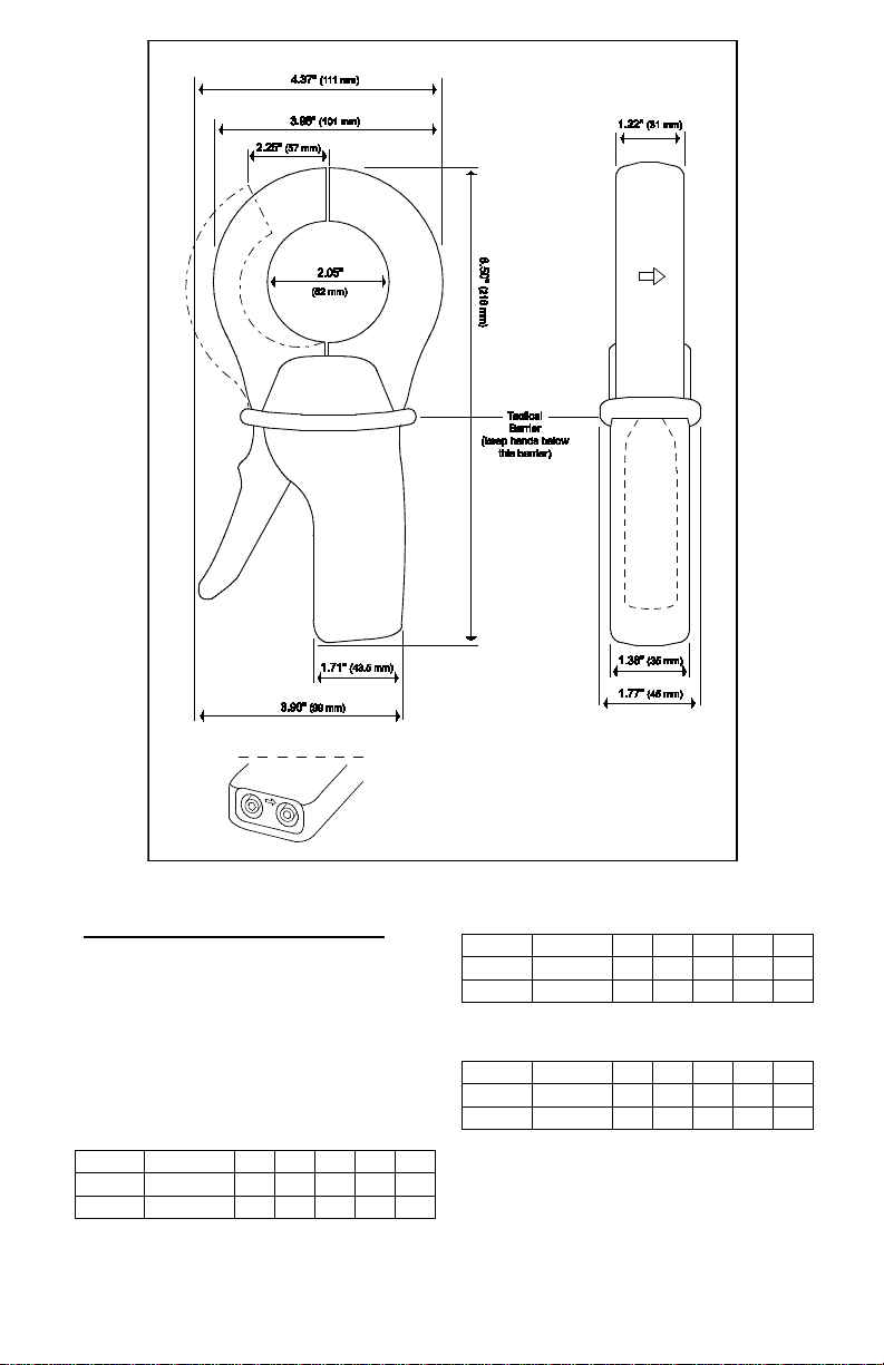
Jaw Opening:
2.25" (57 mm) max.
Maximum Conductor Size:
2.05" (52 mm)
Envelope Protection:
IP 40 (IEC 529)
Drop Test: 1 m (IEC 68-2-32)
Mechanical Shock:
100 g (IEC 68-2-27)
Vibration:
5 to 15 Hz, 0.15 mm (IEC 68-2-6)
15 to 25 Hz, 1 mm
25 to 55 Hz, 0.25 mm
Polycarbonate Material:
Handles: ABS Grey and
Lexan 500R, Red: UL94V0
Jaws: Lexan 500R, Red: UL94V0
Dimensions:
4.37 x 8.50 x 1.77" (111 x 216 x 45mm)
Weight:
1.21 lbs. (550 g)
Output:
Two standard safety banana jacks (4mm)
SAFETY SPECIFICATIONS
Electrical:
Double insulation or reinforced insulation between
the primary or secondar y and the out er cas e of
the handle conforms to IEC 1010-2-032.
Common Mode Voltage:
600V CAT III, Pollution Degree 2
Dielectric Strength:
5550V, 50/60Hz between primary, secondary
and the outer case of the handle
Electromagnetic Compatibility:
EN 50081-1 Class B
EN 50082-2 Electrostatic discharge
IEC 1000-4-2
Radiated field IEC 1000-4-3
Fast transients IEC 1000-4-4
Magnetic field at 50/60 Hz IEC 1000-4-8
ORDERING INFORMATION
AC Current Probe SR634 ............... Cat #2113.48
Accessories:
Banana plug adapter
(to non-recessed plug) ................... Cat #1017.45
Lead, set of 2, 5ft Safety Leads
(1000V CAT IV) ................................ Cat#2152.24
Adapter BNC (Male) –Banana (Female)
(XM-BB) (600V CAT III) ................... Cat#2118.46
Page 4

OPERATION
Please make sure that you have already read and fully understand the WARNING section on page 1.
Making Measurements with the AC Current Probe Model SR634
• Connect the current probe t o an AC current range o n your D MM or ot her cu rrent me asuring i nstrum ent.
The AC Current Probe SR634 is a multi-ratio unit. The outputs are as follows:
Current Flow Output of Probe
in Conductor Ratio 250:5 Ratio 500:5 Ratio 1000:5
100A 2000mA 1000mA 500mA
250A 5A (5000mA) 2500mA 1250mA
Select the 10 A r ange on your DM M or ins trumen t. Use t he switch on the i nside handle to selec t the 10 00:5
range. Clamp the prob e around the condu ctor and work down u ntil the appropriat e range and resoluti on in
reached. Take the reading on the met er and multi ply it b y the ratio selected to obtain the measured c urrent
(e.g, 500mA reading - 500 x 200 = 100,000mA or 100A with th e 100 0:5 ra tio) .
• For best accuracy, avoid if possible, the proximity of other conductors which ma y create nois e.
Tips for Making Precise Measurements
• When using a current probe with a meter, it is important to select the range that provides the best
resolution. Failure to do this may result in measurement errors.
• Make sure that probe ja w mating surfa ces are free of dust and c ontamination . Contaminant s cause air
gaps between the ja ws, increas ing the phase s hift betwe en primary an d seconda ry. It is very cri tical for
power measurement.
MAINTENANCE
Warning:
• For maintenance use only original replacement parts.
• To avoid electrical shock, do not attempt to perform any servicing unless you are qualified to do so.
• To avoid electrical shock and/ or dama ge to the inst rument , do not ge t water or ot her forei gn age nts into
he probe
t
Cleaning:
To ensure optim um performance, it is import ant to keep the probe j aw mating s urfaces cle an at all tim es.
Failure to do so may result i n err or in r e adi n gs. T o c lea n th e pr obe j a ws , us e ver y fin e s an d pa pe r (fin e 600)
to avoid scratching the jaw, then gently clean with a soft oiled cloth.
REPAIR AND CALIBRATION
You must contact ou r Servic e Center f or a Cust omer Serv ice Aut horizati on num ber (CSA# ). This will ensure
that when your instrum ent arrives, i t will be track ed and processed pr omptly. Please write the CSA# o n the
outside of the shipping container.
Chauvin Arnoux
1
5 Faraday Drive • Dover, NH 03820 USA
(800) 945-2362 (Ext. 360) • (603) 74 9-6434 (Ext. 360) • repair@aemc.c om
(Or contact your authori zed di stributor)
NOTE: All customers must obtain a CSA# before returning any instrument.
TECHNICAL AND SALES ASSISTANCE
If you are experiencing a ny tec hnical problem s, or re quir e any assi stanc e with the p roper us e or appl icati on
of this instrument, please contact our technical hotline:
(800) 343-1391 • (508) 698-2115 • techsupport@aemc.com
LIMITED WARRANTY
The current probe is warranted to the owner for a period of two years from the date of original purchas
against defects in manu factur e. This lim ited warrant y is give n by AEMC
from whom it was purchased. T his warranty is void if the u nit has been tampered with, abuse d or if the
defect is related to service not performed by AEMC
Full warranty coverage and product registration is available on our website at: www.aemc.com/warranty.html
Please print the online Warranty Coverage Information for your records.
®
, Inc. d.b.a. AEMC® Instruments
®
Instruments.
®
Instruments, not b y the distri butor
e
99-MAN 100134.v10 03/ 17
 Loading...