

Page 1
AC Current Probe
Models SR601 and SR604
User Manual
DESCRIPTION: The SR601/SR604 (Cat. #2113.43/2113.44) are designed for use in industrial environments.
The ergonomic design allows them to easily attach to cables or small bus bars. The “circular” jaws guarantee
a very good accuracy and low phase shift. The probes have a measurement range up to 1000Arms
continuous and are compatible with any AC ammeter, multimeter, or other current measurement instrument
with an input impedance lower than 5Ω. To achieve the stated accuracy, use the SR601/SR604 with an
ammeter having an accur ac y of 0.7 5% or better.
WARNING
The safety warnings are provided to ensure the safety of personnel and proper operation of the
instrument. Read the instruction completely.
• Use caution on any circ uit: potentially high voltag es and currents may be prese nt and may pose a
shock hazard.
• Do not use the probe if dama ged. Al ways co nnect th e cur rent pr obe to the m easuri ng devi ce bef ore it
is connected around the conductor
• Do not use on non-insulated c onduct or with a potential to gr ound gr eater tha n 600V CAT III pollution
2. Use extreme caution when clamping around bare conductors or bus bars.
• Before each use, inspect the probe; look for cracks in housing or output cable insulation.
• Do not use clamp in wet environment or in locations that hazardous gases exist.
• Do not use the probe anywhere be yond the tactile barrier.
INTERNATIONAL ELECTRICAL SYMBOLS
This symbol signifi es t hat the c urre nt prob e is p rotect ed b y dou ble or r einforc ed ins ulat ion. Us e onl y
factory specified replacement parts when servicing the instrument.
This symbol signifies CAUTION! and requests that the user refer to the user manual before using
the instrument.
This is a type A current sensor. This symbol signifies that application around and removal from
HAZARDOUS LIVE conductors is permitted.
DEFINITION OF MEASUREMENT CATEGORIES
CAT II: For measurements performed on circuits directly connected to the electrical distribution s ystem.
Examples are measurements on household appliances or portable tools.
CAT III: For measurements performed in the building installation at the distribution level such as on
hardwired equipment in fixed installation and circuit breakers.
CAT IV: For measurements performed at the primary electrical supply (<1000V) such as on primary
overcurrent protect ion devices, ripple control units, or meters.
RECEIVING YOUR SHIPMENT
Upon receiving yo ur shipm ent, mak e sure that the c ontent s are co nsistent with th e pack ing list. N otify your
distributor of an y missing i tems. If th e equi pment ap pears to b e damag ed, file a clai m imm ediatel y with the
carrier and notify your distributor at once, giving a detailed description of any damage.
Page 2
Primary current
0.1 to 10A
10A
50A
Accuracy %
≤ 3% + 0.1A
3%
1.5%
Phase shift
N/A
3°
1.5°
Primary current
200A
1000A
1200A
Accuracy %
.75%
0.5%
0.5%
Phase shift
0.75°
0.5°
0.5°
SR601 SR604
ELECTRICAL SPECIFICATIONS
Current Range:
0.1 to 1000A AC, continuous cycle @ ≤ 1kHz
Transformation Ratio: 1000:1
Output Signal:
1mA AC/A AC (1A AC at 1000A)
Accuracy and Phase Shift*:
(*Reference conditions: 23°C±3°K, 20 to 75% RH, 48 to
65 Hz, external magnetic field <40 A/m, no DC
component, no external current carrying conductor, test
sample centered.) Load impedance 5Ω.
Overload: 1200 A for 40mn on, 20mn off
Accuracy: Per IEC 185
Frequency Range : 30Hz to 5kHz; current derating
above 1 kHz using the formula:
Page 3
L
oad Impedance: 5Ω max
Working Voltage: 600V CAT III
Common Mode Voltage: 600V CAT III
Open Secondary Voltage:
< 25V by limiting circuit
Influence of Ad jac ent Conductor:
< 1mA/A AC
Influence of Conductor in Jaw Opening:
0.1% of reading
Influence of Frequency:
From 30 to 48Hz : < 1% of R
From 65 to 1000Hz : < 0.5% of R
From 1kHz to 5kHz : < 1% of R
MECHANICAL
SPECIFICATIONS
Operating Temperature:
14° to 122°F (-10° to 50°C)
Storage Temperature:
-4° to 158°F (-20° to 70°C)
Influence of Temperature:
< 0.1% per 10°K
Influence of Humidity:
From 10 to 90% : 0.1%
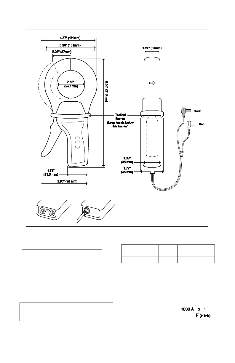
Jaw Opening:
2.25" (57mm) max.
Maximum Conductor Size:
2.05” (52mm)
Envelope Protection:
IP 40 (IEC 529)
Drop Test:
1m (IEC 68-2-32)
Mechanical Shock:
100g (IEC 68-2-27)
Vibration:
5 to 15Hz, 0.15mm (IEC 68-2-6)
15 to 25Hz, 1mm
25 to 55Hz, 0.25mm
Polycarbonate Materi al:
Handles: ABS Grey and
Lexan 500R, Red: UL94V0
Jaws: Lexan 500R, Red: UL94V0
imensions:
D
4.37 x 8.50 x 1.77" (111 x 216 x 45mm)
Weight:
1.21lbs. (550g)
Output:
SR601: Two standard safety banana
jacks (4mm)
SR604: 5ft. (1.5m) lead with safety
4mm banana plug
SAFETY SPECIFICATIONS
Electrical:
Double insulation or reinforced insulation between
the primary or secondar y and the out er cas e of the
handle conforms to IEC 1010-2-032.
Common Mode Voltage:
600V Category III, Polluti on D eg re e 2
Dielectric Strength:
5550V, 50/60Hz between primary, secondary
and the outer case of the handl e
Electromagnetic Compatibility:
EN 50081-1 Class B
EN 50082-2 Electrostatic discharge
IEC 1000-4-2
Radiated field IEC 1000-4-3
Fast transients IEC 1000-4-4
Magnetic field at 50/60Hz IEC 1000-4-8
ORDERING INFORMATION
AC Current Probe SR601 ................ Cat #2113.43
AC Current Probe SR604 ................ Cat #2113.44
Accessories:
Lead, set of 2, 5ft Safety Leads
(1000V CAT IV) .................................. Cat#2152.24
Adapter BNC (Male) –Banana (Female) (XM-BB)
(600V CAT III) ..................................... Cat#2118.46
B
anana plug adapter
(to non-recessed plug) ..................... Cat #1017 .4 5
Page 4

OPERATION
Please make sure that you have already read and fully understand the WARNING section on page 1.
Making Measurements with the AC Current Probe Models SR601/SR604
• Connect the black lead of the current probe t o “common” and the red l ead to the AC curre nt input o
y
our DMM or other curr ent measuring instr ument. Select the appr opriate current r ange (2A AC range).
Clamp the probe around the conductor to be tested with the arro w pointed toward the loa d. If t he r ea din g
is less than 200mA, sel ect th e l o wer ra nge u nti l yo u obt ain the best resolution. R ead th e valu e di splay on
the DMM and multipl y it by the pr obe r atio (10 00/ 1). (If re ading = 0. 65 9A, the c urren t flowin g thro ugh the
probe is 0.659A x 1000 = 659A AC)
• For best accuracy, avoid if possible, the proximity of other conductors which may create noise.
Tips for Making Precise Measurements
• When using a current probe with a meter, it is important to select the range that provides the best
resolution. Failure to do this may result in measurement errors.
• Make sure that p robe jaw mati ng surfaces are free of dust and con tamination. C ontaminants c ause air
gaps between the ja ws, increas ing the phase s hift betwe en primary an d seconda ry. It is very cri tical for
power measurement.
MAINTENANCE
Warning:
• For maintenance use only original replacement parts.
• To avoid electrical shock, do not attempt to perform any servicing unless you are qualified to do so.
• To avoid electric al shock and/or dam age to the i nstrum ent, do no t get wat er or othe r foreign a gents int
t
he probe
Cleaning:
To ensure optim um performa nce, it is important to k eep the pr obe jaw mati ng surfaces clean at all times.
Failure to do so may result i n err or in r e adi n gs. T o c lea n th e pr obe j a ws , us e ver y fin e s an d pa pe r (fin e 600)
to avoid scratching the jaw, then gently clean with a soft oiled cloth.
REPAIR AND CALIBRATION
You must contact ou r Servic e Center f or a Cust omer Serv ice Aut horizati on num ber (CSA# ). This will ensure
that when your instrum ent arrives, i t will be track ed and processed pr omptly. Please write the CSA# o n the
outside of the shipping container.
Chauvin Arnoux
1
5 Faraday Drive • Dover, NH 03820 USA
®
, Inc. d.b.a. AEMC® Instruments
(800) 945-2362 (Ext. 360) • (603) 74 9-6434 (Ext. 360) • repair@aemc.c om
(Or contact your authori zed di stributor)
NOTE: All custom er s mu st o bta in a CS A # before returning any instrument.
TECHNICAL AND SALES ASSISTANCE
If you are experiencing a ny tec hnical problem s, or re quir e any assi stanc e with the p roper us e or appl icati on
of this instrument, please contact our technical hotline:
(800) 343-1391 • (508) 698-2115 • techsupport@aemc.com
LIMITED WARRANTY
The current probe is warranted to the owner for a period of two years from the date of original purchase
against defects in manufacture. This limited warranty is given by AEMC® Ins
from whom it was
purchased. This warranty is void if the unit has been tampered with, abused or if the
truments, not by the distributor
defect is related to service not performed by AEMC® Instruments.
Full warranty coverage and product registration is available on our website at: www.aemc.com/warranty.html
Please print the online Warranty Coverage Information for your records.
n
o
99-MAN 100132.v13 03/17
 Loading...