

Page 1
AC Current Probe
Model SR600
User Manual
DESCRIPTION
The SR600 (Cat. #2113. 42) is designe d for use i n indust rial envi ro nments . The erg onom ic desig n allo ws it to
easily attach to cables or sm all bus ba rs . The “c ircul ar” j aws gua rante e a v er y good a ccurac y an d low phas e
shift. The probe has a mea surement range up to 1000 Arms. con tinuous and is compatible with a ny AC
ammeter, multim eter, or other c urrent measu rement instrum ent with an in put impedance lower than 5Ω. To
achieve the stated accuracy, use the SR600 with an ammeter having an accuracy of 0.75% or better.
WARNING
The safety warnings are provided to ensure the safety of personnel and proper operation of the
instrument. Read the instruction completely.
• Use caution on any circ uit: potentially high voltag es and currents may be prese nt and may pose a
shock hazard.
• Do not use the probe if dama ged. Al ways co nnect th e cur rent pr obe to the m easuri ng devi ce bef ore it
is connected around the conductor
• Do not use on non-insulated c onduct or with a potential to gr ound gr eater tha n 600V C AT III pollutio n
2. Use extreme caution when clamping around bare conductors or bus bars.
• Before each use, inspect the probe; look for cracks in housing or output cable insulation.
• Do not use clamp in wet environment or in locations that hazardous gases exist.
• Do not use the probe anywhere be yond the tactile barrier.
INTERNATIONAL ELECTRICAL SYMBOLS
This symbol signifi es t hat the c urre nt prob e is p rotect ed b y doubl e or rei nforc ed ins ulati on. Use onl y
factory specified replacement parts when servicing the instrument.
This symbol signifies CAUTION! and requests that the user refer to the user manual before using
the instrument.
This is a type A current sensor. This symbol signifies that application around and removal from
HAZARDOUS LIVE conductors is permitted.
DEFINITION OF MEASUREMENT CATEGORIES
CAT II: For measurements performed on circuits directly connected to the electrical distribution system.
Examples are measurements on household appliances or portable tools.
CAT III: For measurements performed in the building installation at the distribution level such as on
hardwired equipment in fixed installation and circuit breakers.
CAT IV: For measurements performed at the primary electrical supply (<1000V) such as on primary
overcurrent protection devices, ripple control units, or meters.
RECEIVING YOUR SHIPMENT
Upon receiving yo ur shipm ent, mak e sure that the c ontent s are co nsistent with th e pack ing list. Notify your
distributor of an y missing i tems. If th e equi pment ap pears to b e damag ed, file a c laim im mediatel y with t he
carrier and notify your distributor at once, giving a detailed description of any damage.
Page 2
ELECTRICAL SPECIFICATIONS
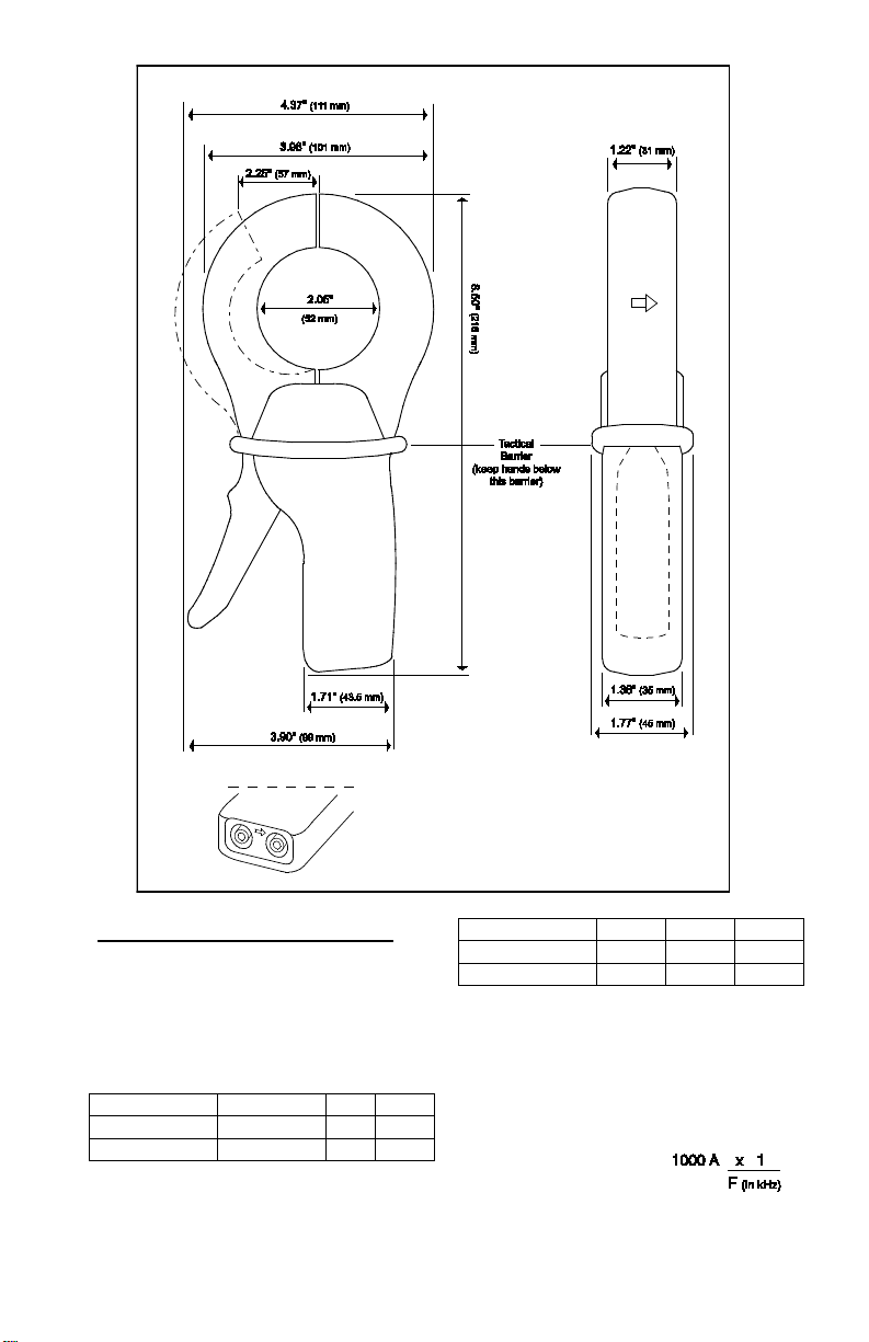
Primary current
0.1 to 10A
10A
50A
Accuracy %
3%
1.5%
Phase shift
N/A
3°
1.5°
Primary current
200A
1000A
1200A
Accuracy %
.75%
0.5%
0.5%
Phase shift
0.75°
0.5°
0.5°
Current Range:
0.1 to 1000A
Output Signal:
1mA
Accuracy and Phase Shift*:
AC, continuous cycle @ ≤ 1kHz
AC/AAC (1AAC at 1000A)
(*Reference conditions: 23°C ±3°K, 20 to 75% RH, 48
to 65 Hz, external magnetic field <40 A/m, no DC
component, no external current carrying conductor,
test sample centered.) Load impedance 1Ω.
Overload: 12 00A f o r 40 mn on, 20 m n off
Accuracy: Per IEC 185
Frequency Range : 30 Hz to 5 kHz; current
derating above 1kHz using the
formula:
Page 3

Load Impedance: 5Ω max
Working Voltage: 600V CAT III
Common Mode Voltage: 600V Cat. III
Influence of Ad jac ent Conductor:
< 1mA/A AC
Influence of Conductor in Jaw Opening:
0.1% of reading
Influence of Frequency:
From 30 to 48 Hz: < 1% of R
From 65 to 1000 Hz: < 0.5% of R
From 1 kHz to 5 kHz: < 1% of R
MECHANICAL
SPECIFICATIONS
Operating Temperature:
14° to 122°F (-10° to 50°C)
Storage Temperature:
-4° to 158°F (-20° to 70°C)
Influence of Temperature:
< 0.1% per 10°K
Influence of Humidity:
From 10 to 90%: 0.1%
Jaw Opening:
2.25" (57mm) max
Maximum Conductor Size:
2.05” (52mm)
Envelope Protection:
IP 40 (IEC 529)
Drop Test:
1 m (IEC 68-2-32)
Mechanical Shock:
100 g (IEC 68-2-27)
Vibration:
5 to 15 Hz, 0.15 mm (IEC 68-2-6)
15 to 25 Hz, 1 mm
25 to 55 Hz, 0.25 mm
Polycarbonate Material:
Handles: ABS Grey and
Lexan 500R, Red: UL94V0
Jaws: Lexan 500R, Red: UL94V0
Dimensions:
4.37 x 8.50 x 1.77" (111 x 216 x 45 mm)
Weight:
1.21 lbs (550 g)
Output:
Two standard safety banana jacks (4mm)
SAFETY SPECIFICATIONS
Electrical:
Double insulation or reinforced insulation between
the primary or secondar y and the out er cas e of
the handle conforms to IEC 101 0-2-032.
Common Mode Voltage:
600V Category III, Polluti on D eg re e 2
Dielectric Strength:
5550V, 50/60 Hz between primary, secondary
and the outer case of the handle
Electromagnetic Compatibility:
EN 50081-1 Class B
EN 50082-2 Electrostatic discharge
IEC 1000-4-2
Radiated field IEC 1000-4-3
Fast transients IEC 1000-4-4
Magnetic field at 50/60 Hz IEC 1000-4-8
ORDERING INFORMATION
AC Current Probe SR600 .................. Cat #2113.42
Accessories:
Lead, set of 2, 5ft Safety Leads
(1000V CAT IV) .................................... Cat#2152.24
Adapter BNC (Male) –Banana (Female) (XM-
BB) (600V CAT III)................................ Cat#2118.46
B
anana plug adapter
(to non-recessed plug) ....................... Cat #1017.45
Page 4

OPERATION
Please make sure that you have already read and fully understand the WARNING section on page 1.
Making Measurements with the AC Current Probe Model SR600
• A set of test lead s is r eq uir ed to take a measu rem en t using the SR600. C on ne ct t h e bl ack test lead to the
black input jack of the SR600 and the ot her end of the test lea d to the “com mon”. Connect t he red test
lead to the red input jack of the SR600 and the other e nd of the tes t lead to the A C curren t input on your
DMM or other curr ent meas uring i nstrum ent. Sel ect the a ppropria te cur rent ra nge (2A A C range) . Clamp
the probe aroun d the cond uctor t o be t ested with t he a rro w poin ted to ward the l oad. If th e rea ding i s les s
than 200 mA, sel ect the lo wer range unti l you obtain the best res olution. Re ad the value display on t he
DMM and multiply it by the probe ratio (1000/1 ). (If reading = 0.659A, the curr ent flowing through the
probe is 0.659A x 1000 = 659A AC)
• For best accuracy, avoid if possible, the proximity of other conductors which may create noise.
Tips for Making Precise Measurements
• When using a current probe with a meter, it is important to select the range t hat provides the best
resolution. Failure to do this may result in measurement errors.
• Make sure that probe ja w mating surfaces ar e free of dust and cont amination. Cont aminants caus e air
gaps between the j aws, incr easing t he phase s hift bet ween prim ary and seco ndary. It i s very c ritical for
power measurement.
MAINTENANCE
Warning:
• For maintenance use only original replacement parts.
• To avoid electrical shock, do not attempt to perform any servicing unless you are qualified to do so.
• To avoid electrical s hock and/or damage to th e instrument, do not get water or other foreign age nts
into the probe.
Cleaning: To ensure optimum performance, it is important to keep the probe jaw mating surfaces clean at all
times. Failure to do so may result in error in readings. To clean the probe jaws, use very fine sand paper (fine
600) to avoid scratching the jaw then gently clean with a soft oiled cloth.
REPAIR AND CALIBRATION
You must contact our Service Center for a Customer Service Authorization number (CSA #) . This wil l ens ur e
that when your instrument arrives, it will be tracked and processed promptly. Please write the CSA# on the
outside of the shipping container.
Chauvin Arnoux
araday Drive • Dover, NH 03820 USA
15 F
®
, Inc. d.b.a. AEMC® Instrum ent s
(800) 945-2362 (Ext. 360) • (60 3) 74 9-6434 (Ext. 360) • repair@aemc.com
(Or contact your authori zed di stributor)
NOTE: All customers must obtain a CSA# before returning any instrument.
TECHNICAL AND SALES ASSISTANCE
If you are experiencing any te chnical problems, or require an y assistance with the proper use or ap plic a tion
of this instrument, please contact our technical hotline:
(800) 343-1391 • (508) 698-2115 • techsupport@aemc.com
LIMITED WARRANTY
The current probe is warranted to the owner for a period of two years from the date of original purchase
against defects in manufacture. This limited warranty is given by AEMC® Instruments, not by the distributor
from whom it was purchased. This warranty is void if the unit has been tampered with, abused or if the defect
is related to service not performed by AEMC® Instruments.
Full warranty coverage and product registration is available on our website at: www.aemc.com/warranty.html
Please print the online Warranty Coverage Information for your records.
.
99-MAN 100131.v10 03/17
 Loading...