

Page 1
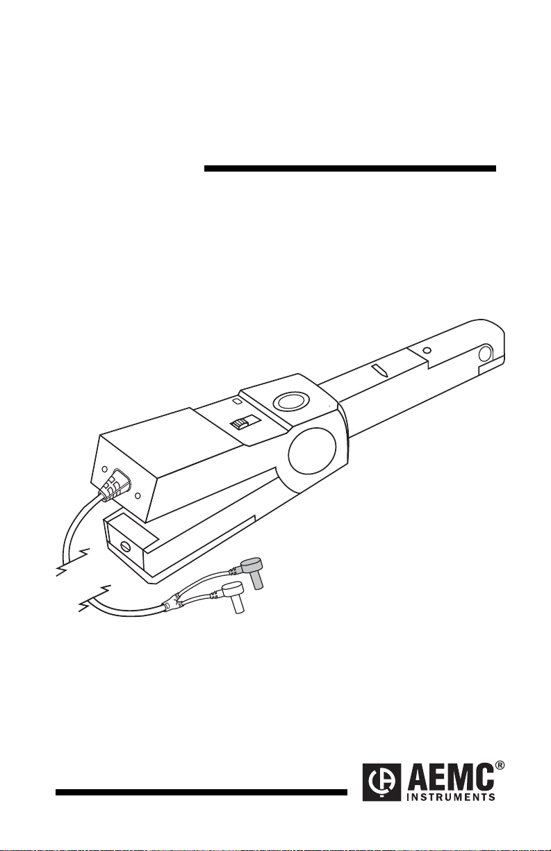
AC/DC Current Probe
Model SL201
USER MANUAL
I
ZERO
1 V/A
1 mV/A
OFF
Page 2

Page 3

Limited Warranty
The AC/DC Current Probe Model SL201 is warranted to the owner for a
period of two years from the date of original purchase against defects
in manufacture. This limited warranty is given by AEMC® Instruments, not
by the distributor from whom it was purchased. This warranty is void if the
unit has been tampered with, abused or if the defect is related to
service not performed by AEMC® Instruments.
For full and detailed warranty coverage, please read the Warranty Coverage
Information, which is attached to the Warranty Registration Card (if
enclosed) or is available at www.aemc.com. Please keep the Warranty
Coverage Information with your records.
What AEMC
If a malfunction occurs within the warranty period, you may return the
instrument to us for repair, provided we have your warranty
information on file or a proof of purchase. AEMC® Instruments will, at its
option, repair or replace the faulty material
®
Instruments will do:
registration
YOU CAN NOW REGISTER ON LINE AT:
www.aemc.com
Warranty Repairs
First, request a Customer Service Authorization Number (CSA#) by phone or
by fax from our Service Department (see address below), then return the
instrument along with the signed CSA Form. Please write the CSA# on the
outside of the shipping container. Return the instrument, postage or
shipment pre-paid to:
Chauvin Arnoux
15 Faraday Drive • Dover, NH 03820 USA
Tel: (800) 945-2362 (Ext. 360)
(603)
Fax: (603) 742-2346 or (603) 749-6309
repair@aemc.com
®
, Inc. d.b.a. AEMC® Instruments
749-6434 (Ext. 360)
Caution: To protect yourself against in-transit loss, we recommend you
insure your returned material.
NOTE: All customers must obtain a CSA# before returning any
instrument.
Page 4

Table of Contents
Warning
International Electrical Symbols................................................................3
Definition of Measurement Categories......................................................4
Receiving Your Shipment..........................................................................4
Packaging..................................................................................................4
Compatibility..............................................................................................4
Description ................................................................................................5
Control and Connector Identification.........................................................5
Specifications............................................................................................6
Frequency Response Curves (Typical).....................................................9
Operation...................................................................................................9
Maintenance............................................................................................11
Repair and Calibration ............................................................................12
Technical and Sales Assistance .............................................................12
.....................................................................................................3
Electrical Specifications.........................................................................6
Mechanical Specifications.....................................................................7
Safety Specifications.............................................................................8
Connection ............................................................................................9
Zeroing the Probe................................................................................10
Current Measurement..........................................................................10
Warning ...............................................................................................11
Cleaning...............................................................................................11
Battery Replacement...........................................................................11
Page 5
AC/DC Current Probe Model SL201
Warning
These safety warnings are provided to ensure the safety of
personnel and proper operation of the instrument.
• Read the instruction manual completely and follow all the
safety information before attempting to use or service this
rument.
inst
Use caution on any circuit: Potentially high voltages and
•
currents may be present and may pose a shock ha
Read the safety specifications section prior to usi
•
curre
nt probe. Never exceed the maximum voltage
given.
•
Safety is the responsibility of the operat
•
ALWAYS connect the current probe to the disp
before
ALWAYS inspect the instrument, probe, probe
•
output termi
immediately.
•
NEVER use the current probe on electric
above 600V
extreme caution whe
bus ba
clamping the probe onto the sample being test
nals prior to use. Replace any defective pa
in overvoltage ca
n clamping around bare conductors or
rs.
or.
al conductors rated
tegory III (CAT III). Use
zard.
ng the
ratings
lay device
ed.
cable, and
rts
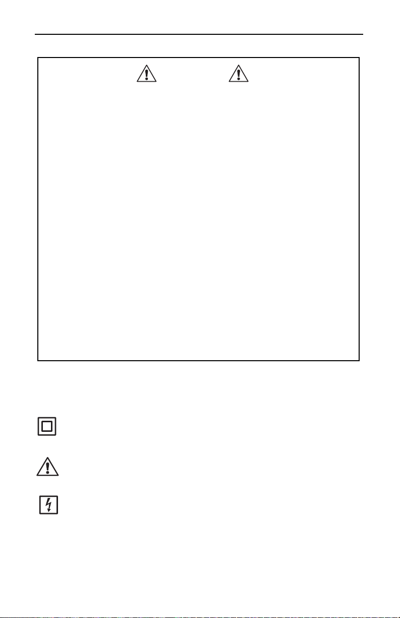
International Electrical Symbols
This symbol signifies that the current probe is protected by double
or reinforced insulation. Use only factory specified replacement
parts when servicing the instrument.
This symbol signifies CAUTION! and requests that the user refer
to the user manual before using the instrument.
This is a type A current sensor. This symbol signifies that
application around and removal from HAZARDOUS LIVE
conductors is permitted.
- 3 -
Page 6

AC/DC Current Probe Model SL201
Definition of Measurement Categories
Cat. IV: For measurements performed at the primary electrical supply
(<1000V) such as on primary overcurrent protection devices,
ripple control units, or meters
Cat. III: For measurements performed in the building installation at the
distribution level such as on hardwired equipment in fixed
installation and circuit breakers.
Cat. II: For measurements performed on circuits directly connected to
the electrical distribution system. Examples are measurements
on household appliances or portable tools.
Receiving Your Shipment
Upon receiving your shipment, be sure that the contents are consistent
with the packing list. Notify your distributor of any missing items. If the
equipment appears to be damaged, file a claim immediately with the
carrier and notify your distributor with a detailed description of any
damage. Save the damaged packing container to substantiate your claim.
Packaging
The AC/DC Current Probe Model SL201 (Cat. #1201.40) is shipped with
one 9V battery and this user manual.
Compatibility
The AC/DC Current Probe Model SL201 is compatible with any DMM,
voltmeter, or other voltage-measuring instrument which has the following
features:
• Range and resolution capable of displa
Voltmeter accuracy (uncertainty) of 0.75% or better to take
•
advantag
• Minimum input impedance of 100kΩ (1 V/A range) or 1kΩ
(10mV/A ran
e of the accuracy of the probe.
ge).
ying 1mV of input.
full
- 4 -
Page 7

AC/DC Current Probe Model SL201
Description
AC/DC Current Probe Model SL201 measures low DC or AC from 50mA
to 150A
DC/120AAC. This battery-powered clamp-on probe may be used
with digital multimeters, voltmeters, or other voltage-measuring
instruments. The probe jaws clamp around the conductor under test,
allowing current measurements without breaking the circuit. Hall sensor
technology senses the magnetic field produced by the current measured,
and generates a millivolt DC or AC output signal. The narrow jaw is
designed for optimum use in crowded wiring in industrial and automotive
environments.
Control and Connector Identification
Current Flow for DC Measurements
Zero Adjust Knob
Range Selection Switch
Battery
Compartment
Screw
Power Indication LED
1 V/A
1 mV/A
OFF
Figure 1
- 5 -
ZERO
I
ø
= 0.46"
(11.8 mm)
Battery Compartment Cover
Page 8

AC/DC Current Probe Model SL201
Specifications
ELECTRICAL SPECIFICATION S
Current Range:
50mA to 150A
Output Signal:
1mV/mA and 1mV/A AC or DC
Accuracy and Phase Shift*:
Range 1 mV/mA (1 V/A) 1mV/A
Current Range
AC/DC in two ranges
50mA to 2A
50mA to 1.5A
DC
AC
500mA to 150A
Output Signal
1V at 1A
AC/DC 100mV at 100AAC/DC
500mA to 100A
1.5% rdg. ± 30mA
Accuracy %
of Reading
2% of reading ± 20mA
100 to 150A
± 3% rdg
100 to 120A
± 3% rdg
Frequency
DC to 2kHz DC to 8kHz
Range
Phase Shift
Min Load
Impedance
Noise
DC to 65Hz: 3° DC to 65Hz: 1°
100kΩ
DC to 1Hz: 3 mV
1Hz to 10kHz: 10mV
10 to 100kHz: 18mV
10kΩ
DC to 1Hz: 3µV
1Hz to 10kHz: 10µV
10 to 100kHz: 18µV
Working Voltage: 600V max (conductor to ground)
Float Voltage: 600V max (output to ground)
AC/DC:
DC:
AC:
(*Reference conditions: 23°C ± 5°K, 20 to 75% RH, 48 to 65 Hz, external magnetic field < 40
A/m, no external current carrying conductor, test sample centered, load impedance 1 M
Ω
.)
- 6 -
Page 9

AC/DC Current Probe Model SL201
MECHAN
ICAL SPECIFICATIONS
Operating Temperature:
32° to 122°F (0° to 50°C)
Storage Temperature:
-22° to 176°F (-30° to 80°C)
Temperature Influence: < 0.2% per °C
Operating Relative Humidity:
10° to 30°C: 85% ±5% RH
(without condensation)
40° to 50°C: 45% ±5% RH
(without condensation)
Battery:
9V alkaline (NEDA 1604A, IEC 6LR61)
Battery Life: 68 hours typical
Typical Consumption: 6mA
Low Battery:
Green LED when ≥ 6.5V
Maximum Cable Diameter:
0.46" (11.8mm)
Zero Adjustment:
20 turn potentiometer
Handle:
®
Lexan
920 A, UL 94 V2
Case Protection:
IP20 per IEC 529
Drop Test:
1.0 m on 38mm of oak on concrete;
test according to IEC 1010
Mechanical Shock:
100G, test per IEC 68-2-27
- 7 -
Page 10

AC/DC Current Probe Model SL201
Vibration:
Test per IEC 68-2-6,
Frequency Range:
10Hz to 55Hz
Amplitude: 0.15mm
Dimensions:
9.09 x 1.42 x 2.64" (231 x 36 x 67mm)
Weight:
11.6 oz (330g) with battery
Color:
Dark gray
Output:
5 ft (1.5m) lead with safety 4mm banana plugs
SAFETY SPECIFICATIONS
Electrical:
- 600V Category III, Pollution: 2
- 300V Category IV, Pollution: 2
Double insulation or reinforced insulation between primary or se condary
and outer case of handle per IEC 1010-2-32
Electromagnetic Compatibility
EN 50081-1 Class B
EN 50082-2 Electrostatic discharge IEC 1000-4-2
Radiated field IEC 1000-4-3
Fast transients IEC 1000-4-4
Magnetic field at 50/60 Hz IEC 1000-4-8
- 8 -
Page 11

AC/DC Current Probe Model SL201
Frequency Response Curves (Typical)
%
10
0
-10
-20
1 mV/mA
1
-30
-40
1 10 100 1000 10000 Hz
Operatio
1 mV/A
2
1
n
2
Connection
Connect the current probe to the multimeter or other instrument. Be sure
to observe the polarities: red = positive terminal, black = common
terminal. The Current Probe Model SL201 has a dual output, DC V
output in DC and AC V output in AC. The “1V/A” range has an output
signal of 1mV/mA AC/DC with an output of 2 volts representing 2 amps
present in the conductor being measured. The “1mV/A” range has an
output signal of 1mV/A AC/DC with an output of 50 millivolts representing 50 amps present in the conductor being measured. Select the
multimeter range which best corresponds to the measured current. For
better reading stability, you may use the DMM 2 Volt range and let the
probe “warm-up”, for one minute before zeroing.
- 9 -
Page 12

AC/DC Current Probe Model SL201
Zeroing the Probe
When the Current Probe Model SL201 has been used for a current
measurement and then removed from the conductor, a small amount of
residual magnetism often remains in the core. This residual magnetism
will cause the voltmeter to show a small DC reading even though there is
no current passing through the jaws of the probe. The residual
magnetism should not cause a problem for AC current measurement
because the AC voltage function in most multimeters is AC coupled. DC
offset caused by the residual magnetism will contribute to reading errors,
but can be minimized by using the zero adjust knob (see Figure 1) to
show a reading of 0 ± a few counts on the multimeter (probe not clamped
on a conductor).
There will always be some instability and noise generated by the Hall
sensor, the earth magnetic field and environmental noise. This is
particularly noticeable on the most sensitive range 1V/A (1mV/mA)
where you may have up to 20mV of uncertainty (see accuracy) which
cannot be “zeroed out”. “Zero” the probe while it is connected to the
DMM and on the range to be used. Let the probe “warm-up” for one
minute before zeroing. Turn the zero adjust knob until the probe is
zeroed.
Current Measurement
Select the appropriate range on your multimeter. Zero the probe in DC
and in DC coupled AC measurements. Observe the output polarities for
DC measurement. Clamp the probe on the conductor to be measured
and read the current flowing directly on your meter. The output of the
probe is 1mV/A AC/DC or 1mV/mA AC/DC. If your meter indicates a
negative reading during DC measurements, this simply means that the
current flow is in the opposite direction of the arrow marked “I” on the
probe or that the probe connections are reversed (polarity). After
measurement, turn the probe off.
- 10 -
Page 13

AC/DC Current Probe Model SL201
Maintenance
Warning
• For maintenance use only specified replacement parts.
• Avoid electrical shock: do not attempt to perform any servicing unless
you are qu
•
Avoid electrical shock and/or damage to the instrument: do not get
water or other foreign agents into the electronic modu
Also see warning on page
•
Cleaning
Be sure that mating surfaces of the jaw are free of dirt or foreign matter.
If they are rusted, gently clean with a soft, lightly oiled cloth. Do not leave
excessive oil residue.
Battery Replacement
When the probe is turned on, the green battery indication LED should
light up. If not, replace the 9V battery (see figure 1).
To replace the battery, disconnect the probe from the circuit and the
DMM. Turn the probe “OFF”. Unscrew the battery compartment screw
and pull out the battery compartment cover. Replace the battery and put
the cover back on. Do not replace the battery while probe is in use.
alified to do so.
le.
4.
- 11 -
Page 14

AC/DC Current Probe Model SL201
Repair and Calibration
To ensure that your instrument meets factory specifications, we recommend
that it be submitted to our factory Service Center at one-year intervals for
recalibration, or as required by other standards or internal procedures.
For instrument repair and calibration:
You must contact our Service Center for a Customer Service Authorization
number (CSA#). This will ensure that when your instrument arrives, it will be
tracked and processed promptly. Please write the CSA# on the outside of
the shipping container. If the instrument is returned for calibration, we need
to know if you want a standard calibration, or a calibration traceable to
N.I.S.T. (includes calibration certificate plus recorded calibration data).
®
Chauvin Arnoux
d.b.a. AEMC
15 Faraday Drive
Dover, NH 03820 USA
Tel: (800) 945-2362 (Ext. 360)
(603)
Fax: (603) 742-2346 or (603) 749-6309
repair@aemc.com
(Or contact your authorized distributor)
Costs for repair, standard calibration, and calibration traceable to N.I.S.T. are
available.
NOTE: All customers must obtain a CSA# before returning any
instrument.
, Inc.
®
Instruments
749-6434 (Ext. 360)
Technical and Sales Assistance
If you are ex
assistance with the proper operation or application of your instrument,
lease call, fax or e-mail our technical support hotline:
p
Chauvin
Phone: (800) 945-2362 (Ext. 351) • (603)
Fax: (603) 742-2346
E-m
periencing any technical problems, or require any
Arnoux®, Inc. d.b.a. AEMC® Instruments
749-6434 (Ext. 351)
ail: techsupport@aemc.com
- 12 -
Page 15

Page 16

Chauvin Arnoux®, Inc. d.b.a AEMC® Instruments
15 Faraday Drive • Dover, NH 03820 USA
99-MAN 100006 v7 02/18
www.aemc.com
 Loading...