

Page 1
Power Energy Logger
Model PEL 102 & PEL 103
User Manual
ENGLISH
www.aemc.com
®
CHAUVIN ARNOUX GROUP
Page 2

Copyright © Chauvin Arnoux®, Inc. d.b.a. AEMC® Instruments. All rights reserved.
No part of this documentation may be reproduced in any form or by any means (including electronic storage and retrieval or translation into any other
language) without prior agreement and written consent from Chauvin Arnoux
®
, Inc., as governed by United States and International copyright laws.
Chauvin Arnoux®, Inc. d.b.a. AEMC® Instruments
15 Faraday Drive • Dover, NH 03820 USA
Tel: (800) 945-2362 or (603) 749-6434 • Fax: (603) 742-2346
®
This documentation is provided “as is,” without warranty of any kind, express, implied, or otherwise. Chauvin Arnoux
effort to ensure that this documentation is accurate; but does not warrant the accuracy or completeness of the text, graphics, or other information contained in this documentation. Chauvin Arnoux
®
, Inc. shall not be liable for any damages, special, indirect, incidental, or inconsequential; including (but
, Inc. has made every reasonable
not limited to) physical, emotional or monetary damages due to lost revenues or lost profits that may result from the use of this documentation, whether
or not the user of the documentation has been advised of the possibility of such damages.
Chauvin Arnoux®, Inc, AEMC®, DataView®, AmpFlex®, MiniFlex® and PowerPad® are registered trademarks of AEMC® Instruments.
Page 3
Thank you for purchasing a Power Energy Logger Model PEL 102 or PEL 103
For best results from your instrument and for your safety, read the enclosed operating instructions carefully and comply
with the precautions for use. These products must be only used by qualified and trained users.
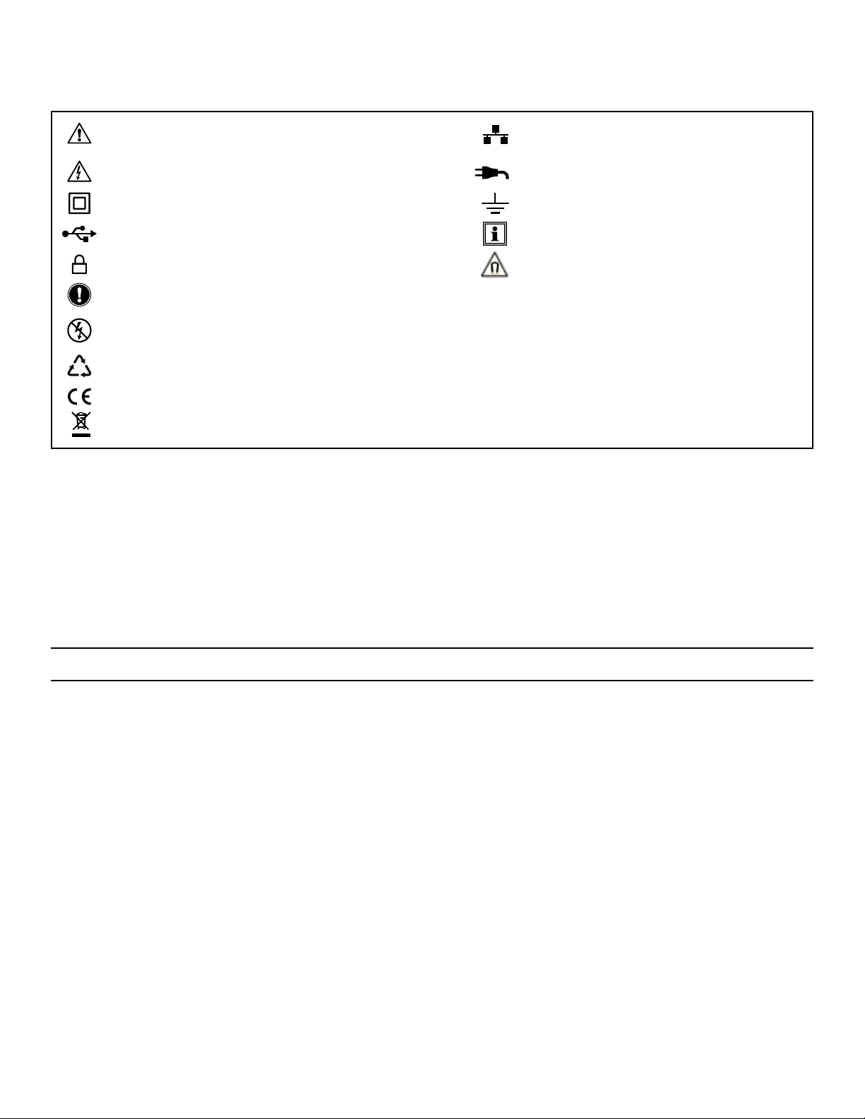
WARNING, risk of DANGER! The operator must refer to
these instructions whenever this danger symbol appears.
CAUTION! Risk of electric shock. The voltage at the
parts marked with this symbol may be dangerous.
Equipment is protected by double insulation. Ground/Earth.
USB socket. Useful information or hint to read.
SD Card.
Important instructions to read and to fully understand.
Must not be applied to or removed from bare conductors carrying dangerous voltages.
Type B current sensor as per EN 61010-2-032.
The product has been declared recyclable after analysis of its life cycle in accordance with the ISO14040 standard.
The CE marking guarantees conformity with European directives and with regulations covering EMC.
The trash can with a line through it means that in the European Union, the product must undergo selective disposal for the
recycling of electric and electronic material, in compliance with Directive WEEE 2002/96/EC.
Ethernet socket (RJ45).
Main power supply input.
Magnetic fields can damage hard drives and
medical devices.
Definition of Measurement Categories (CAT)
■ CAT IV Measurement category IV corresponds to measurements taken at the source of low-voltage installations.
Example: power feeders, counters and protection devices.
■ CAT III Measurement category III corresponds to measurements on building installations.
Example: distribution panel, circuit-breakers, machines or fixed industrial devices.
■ CAT II Measurement category II corresponds to measurements taken on circuits directly connected to low-voltage installations.
Example: power supply to domestic electrical appliances and portable tools.
PRECAUTIONS FOR USE
This instrument complies with safety standard IEC 61010-2-030, the leads comply with IEC 61010-031 for voltages of 1000V in
measurement category III or 600V in measurement category IV and the current sensors comply with IEC 61010-2-032. Failure to observe
the safety instructions may result in electric shock, fire, explosion, and destruction of the instrument and of the installations.
■ The operator and/or the responsible authority must carefully read and clearly understand the various precautions to be taken
in use. Sound knowledge and a keen awareness of electrical hazards are essential when using this instrument.
■ For your safety, use only the compatible leads and accessories delivered with the instrument, which comply with IEC
standard 61010-031 (2002). When sensors or accessories having a lower voltage rating and/or category are connected to the
instrument, the lower voltage and/or category applies to the system so constituted.
■ Before each use, check that the leads, enclosures, and accessories are in perfect condition. Any lead, sensor or accessory
on which the insulation is damaged (even partially) must be repaired or scrapped.
■ Do not use the instrument on networks for which the voltage or category exceeds those mentioned.
■ Do not use the instrument if it seems to be damaged, incomplete, or poorly closed.
■ Use only the AC power adapter and battery pack supplied by the manufacturer, which include specific safety features.
■ When removing and replacing the battery and/or the SD-Card, make sure that the device is disconnected and switched off.
■ We recommend using Personal Protection Equipment where required.
■ Keep your hands away from unused terminals.
■ If the instrument is wet, dry it before connecting it.
■ All troubleshooting and metrological checks must be performed by authorized (competent and accredited) personnel, with
the instrument completely disconnected.
Page 4

TABLE OF CONTENTS
1. INTRODUCTION .............................................................................................................. 6
1.1 Receiving Your Shipment ........................................................................................................................................6
1.2 Ordering Information ...............................................................................................................................................6
1.2.1 Accessories ..................................................................................................................................................7
1.2.2 Replacement Parts.......................................................................................................................................7
2. PRODUCT FEATURES ..................................................................................................... 8
2.1 Description .............................................................................................................................................................. 8
2.2 Front Panel Features ...............................................................................................................................................9
2.3 Back Panel Features .............................................................................................................................................10
2.4 Lead Inputs ...........................................................................................................................................................10
2.5 Installation of the Color-coded ID Markers ...........................................................................................................11
2.6 Connection Features ............................................................................................................................................. 11
2.7 Mounting and Location .........................................................................................................................................12
2.8 Button Functions ................................................................................................................................................... 12
2.9 LCD Display (PEL 103) .......................................................................................................................................... 12
2.10 LED Status ..........................................................................................................................................................13
2.11 Memory Capacity ................................................................................................................................................ 15
3. OPERATION ................................................................................................................... 16
3.1 Charging the Battery .............................................................................................................................................16
3.2 Operating the PEL ................................................................................................................................................. 16
3.3 Turning the Instrument ON/OFF
3.3.1 Turning the PEL ON ...................................................................................................................................17
3.3.2 Turning the PEL OFF ..................................................................................................................................17
3.4 Starting/Stopping a Recording and Enabling Bluetooth ....................................................................................... 18
3.5 Connections .......................................................................................................................................................... 18
3.5.1 Power Supply ............................................................................................................................................. 18
3.5.2 Standby Mode (and Display Brightness) ....................................................................................................19
3.5.3 Memory Card (SD-Card) ............................................................................................................................19
3.5.4 USB Connection to the PEL ......................................................................................................................19
3.5.5 LAN Ethernet Connection to the PEL ........................................................................................................ 19
3.5.6 Bluetooth Connection to the PEL ..............................................................................................................20
3.5.6.1 Pairing using Windows 7....................................................................................................................20
3.6 Distribution Systems and PEL Hook-ups .............................................................................................................. 22
3.6.1 Single Phase 2-Wire ................................................................................................................................ 22
3.6.2 Single Phase 3-Wire (Split Phase from a center tap transformer) ............................................................22
3.6.3 3-Phase 3-Wire Power Networks .............................................................................................................. 23
3.6.3.1 3-Phase 3-Wire ∆ (with 2 current sensors).........................................................................................23
3.6.3.2 3-Phase 3-Wire ∆ (with 3 current sensors).........................................................................................23
3.6.3.3 3-Phase 3-Wire Open ∆ (with 2 current sensors) ............................................................................... 24
3.6.3.4 3-Phase 3-Wire Open ∆ (with 3 current sensors] ............................................................................... 24
3.6.3.5 3-Phase 3-Wire Y (with 2 current sensors) ........................................................................................25
............................................................................................................................ 17
2
Power & Energy Logger Model PEL 102 and PEL 103
Page 5

3.6.3.6 3-Phase 3-Wire Y (with 3 current sensors] ........................................................................................25
3.6.3.7 3-Phase 3-Wire ∆ Balanced (with 1 current sensor) ..........................................................................26
3.6.4 3-Phase 4-Wire Y Power Networks ...........................................................................................................26
3.6.4.1 3-Phase 4-Wire Y (with 3 current sensors) ........................................................................................26
3.6.4.2 3-Phase 4-Wire Y Balanced ............................................................................................................... 27
3.6.4.3 3-Phase 4-Wire Y 2½ Element ........................................................................................................... 27
3.6.5 3-Phase 4-Wire ∆ ....................................................................................................................................... 28
3.6.5.1 3-Phase 4-Wire ∆ ............................................................................................................................... 28
3.6.5.2 3-Phase 4-Wire Open ∆ .....................................................................................................................28
3.6.6 DC Power Networks ..................................................................................................................................29
3.6.6.1 DC 2-Wire ..........................................................................................................................................29
3.6.6.2 DC 3-Wire ..........................................................................................................................................29
3.6.6.3 DC 4-Wire ..........................................................................................................................................30
3.7 LCD Display Modes (PEL 103 Only) ...................................................................................................................... 31
3.7.1 Base Measurements - Displayed Valuess
3.7.2 Energy - Displayed Values
3.7.3 Harmonic Display Values
3.7.4 Max Display Values
3.7.5 Information Display Values
....................................................................................................................................... 34
......................................................................................................................................... 37
................................................................................................................................................... 38
...................................................................................................................................... 39
................................................................................................. 31
3.7.6 Conguratios (PEL 103) .............................................................................................................................40
4. PEL CONTROL PANEL - DATAVIEW® SOFTWARE ..........................................................42
4.1 Installing DataView ................................................................................................................................................42
4.2 Connecting to a PEL .............................................................................................................................................48
4.2.1 Add an Instrument Wizard .........................................................................................................................49
4.2.2 USB Connection ........................................................................................................................................50
4.2.3 Ethernet Network Connection .................................................................................................................... 52
4.2.4 Bluetooth Connection ................................................................................................................................ 53
4.3 PEL Control Panel .................................................................................................................................................54
4.3.1 Opening and Using the Control Panel .......................................................................................................54
4.3.2 Modifying a Connection Type ....................................................................................................................57
4.3.3 Reconnecting and Disconnecting an Instrument ....................................................................................... 57
4.3.4 Removing an Instrument from the PEL Network .......................................................................................57
4.4 Conguring the PEL ..............................................................................................................................................58
4.4.1 General Options ......................................................................................................................................... 59
4.4.2 Communication Options ............................................................................................................................ 60
4.4.3 Measurement Tab Options ......................................................................................................................... 62
4.4.4 Current Sensors and Ratios ....................................................................................................................... 63
4.4.5 Recording Tab Options ..............................................................................................................................65
4.4.6 Meters Tab Options .................................................................................................................................... 67
4.4.7 Conguring and Recording Data Example ................................................................................................68
4.4.8 Modifying an Instrument’s Conguration ...................................................................................................69
4.5 Downloading Recorded Data ................................................................................................................................69
4.6 Using the Download Folder ................................................................................................................................... 71
4.7 PEL Reports ..........................................................................................................................................................72
Power & Energy Logger Model PEL 102 and PEL 103
3
Page 6

4.7.1 Specifying the Default Report Template ....................................................................................................72
4.8 Power & Energy Logger (PEL) Android App ..........................................................................................................72
5. SPECIFICATIONS ......................................................................................................... 74
5.1 Reference Conditions ............................................................................................................................................ 74
5.2 Electrical Specications ........................................................................................................................................74
5.2.1 Voltage Inputs ............................................................................................................................................74
5.2.2 Current Inputs ............................................................................................................................................74
5.2.3 Accuracy Specications (excluding current sensors) ................................................................................75
5.2.3.1 Specications at 50/60Hz ................................................................................................................. 75
5.2.3.2 Specications @ 400Hz .....................................................................................................................77
5.2.3.3 Specications @ DC...........................................................................................................................77
5.2.3.4 Temperature .......................................................................................................................................78
5.2.3.5 Common Mode Rejection .................................................................................................................. 78
5.2.3.6 Magnetic Field Inuence .................................................................................................................... 78
5.2.4 Current Sensors ......................................................................................................................................... 78
5.2.4.1 Precautions for Use ...........................................................................................................................78
5.2.4.2 Use and Characteristics .....................................................................................................................78
5.2.4.3 MiniFlex® MA193 ................................................................................................................................ 79
5.2.4.4 Other Current Sensors ....................................................................................................................... 79
5.2.4.5 Accuracy ............................................................................................................................................ 81
5.3 Bluetooth ............................................................................................................................................................... 83
5.4 Power Supply ........................................................................................................................................................ 83
5.5 Mechanical Specifications ....................................................................................................................................84
5.6 Environmental Specications ................................................................................................................................ 84
5.7 Safety Specications .............................................................................................................................................84
5.8 Electromagnetic Compatibility ..............................................................................................................................84
6. MAINTENANCE ............................................................................................................. 85
6.1 Battery ................................................................................................................................................................... 85
6.2 Battery Indicator .................................................................................................................................................... 85
6.3 Cleaning ................................................................................................................................................................85
6.4 Updating the Internal Software ............................................................................................................................86
APPENDIX A ...................................................................................................................... 87
A.1 Measurements ......................................................................................................................................................87
A.1.1 Definition .................................................................................................................................................... 87
A.1.2 Sampling .................................................................................................................................................... 87
A.1.2.1 Sampling Period ................................................................................................................................87
A.1.2.2 Locking of Sampling Frequency ........................................................................................................ 88
A.1.2.3 AC/DC ................................................................................................................................................88
A.1.2.4 Measurement of Neutral Current .......................................................................................................88
A.1.2.5 “1 second” Quantities ........................................................................................................................88
A.1.2.6 Aggregation .......................................................................................................................................88
A.1.2.7 Max .................................................................................................................................................... 88
A.1.2.8 Energy Calculations ........................................................................................................................... 89
4
Power & Energy Logger Model PEL 102 and PEL 103
Page 7

A.2 Measurement Formulas ........................................................................................................................................89
A.3 Aggregation ........................................................................................................................................................... 90
A.4 Supported Electrical Networks ............................................................................................................................. 92
A.5 Phase Order .......................................................................................................................................................... 94
A.5.1 Current Phase Order .................................................................................................................................. 94
A.5.2 Voltage Phase Order ..................................................................................................................................95
A.5.3 Current vs Voltage Phase Order ................................................................................................................96
A.6 Quantities According to the Supply Systems .......................................................................................................97
A.7 Glossary of Terms .................................................................................................................................................99
Repair and Calibration .................................................................................................... 102
Technical and Sales Assistance ......................................................................................102
Limited Warranty ............................................................................................................103
Warranty Repairs ............................................................................................................103
Power & Energy Logger Model PEL 102 and PEL 103
5
Page 8
1. INTRODUCTION
1.1 Receiving Your Shipment
Upon receiving your shipment, make sure that the contents are consistent with the packing list. Notify your distributor of any
missing items. If the equipment appears to be damaged, file a claim immediately with the carrier and notify your distributor
at once, giving a detailed description of any damage. Save the damaged packing container to substantiate your claim.
1.2 Ordering Information
Power & Energy Logger Model PEL 102 (no LCD, w/3 MA193-10-BK sensors) ............................................ Cat. #2137.51
Power & Energy Logger Model PEL 103 (with LCD, w/3 MA193-10-BK sensors) .......................................... Cat. #2137.52
Power & Energy Logger Model PEL 102 (no LCD, no sensors) ...................................................................... Cat. #2137.61
Power & Energy Logger Model PEL 103 (with LCD, no sensors) .................................................................... Cat. #2137.62
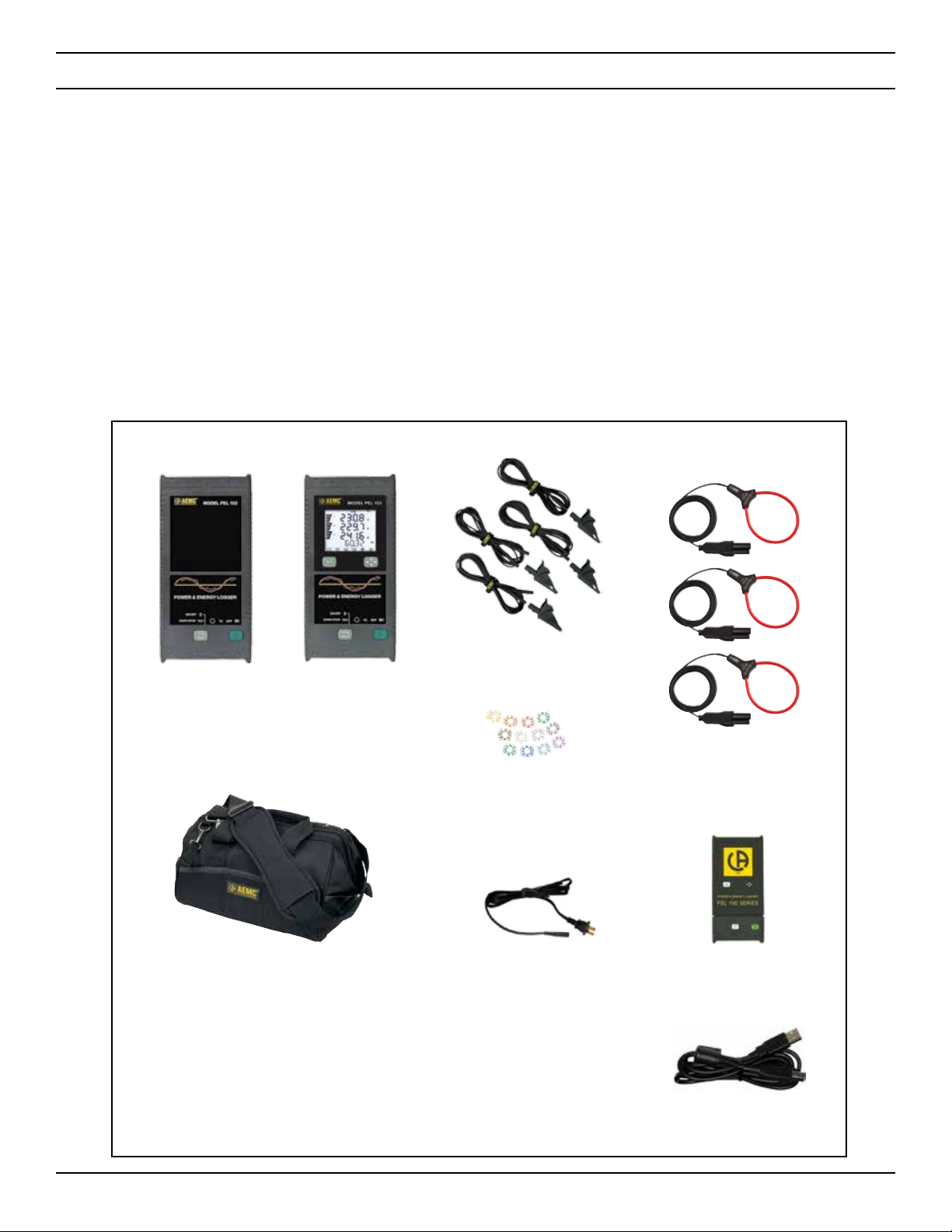
Shipping Contents:
OR
(1) of the following:
Power Energy Logger Model PEL 102
Power Energy Logger Model PEL 103
Cat. #2137.51 or Cat. #2137.52
(1) Small Classic Tool Bag
Cat. #2133.72
(4) Black Test Leads and Alligator Clips
Cat. #2137.76
(12) Color-coded ID Markers
Cat. #2140.45
(1) Power Cord, 5 ft 115V
Cat. #5000.14
(3) MiniFlex® MA193-10-BK
Cat. #2140.48
(included only with
the purchase of
Cat. #2137.51 or Cat. #2137.52)
(1) USB SD-Card Adapter
Cat. #5000.45
Also Included:
(1) Safety Sheet for the PEL
(1) Safety Sheet for the MiniFlex® Sensors
(1) Compliance Sheet
(1) 2 GB SD-Card
(1) Quick Start User Guide
(1) 4 GB USB Stick with User Manual & DataView® Software
(1) Battery (NiMH AAA 8.4V) - Cat.#2137.81
6
Power & Energy Logger Model PEL 102 and PEL 103
(1) 5 ft USB Cable
Cat. #2140.46
Page 9

1.2.1 Accessories
USB cable, A/B 10 ft (3m) ................................................................................................................................Cat. #2136.80
PEL Power Adapter ..........................................................................................................................................Cat. #2137.77
AC/DC Current Probe Model J93 .....................................................................................................................Cat. #2140.49
AC/DC Current Probe Model MR193-BK .........................................................................................................Cat. #2140.28
AC Current Probe Model MN93-BK .................................................................................................................Cat. #2140.32
AC Current Probe Model SR193-BK ................................................................................................................Cat. #2140.33
AmpFlex
AmpFlex® Sensor 36" Model 193-36-BK (black connector) ...........................................................................Cat. #2140.35
AC Current Probe Model MN193-BK (black connector) ................................................................................Cat. #2140.36
MiniFlex® Current Sensor 10" Model MA193-10-BK (black connector) ...........................................................Cat. #2140.48
®
Sensor 24" Model 193-24-BK (black connector) ...........................................................................Cat. #2140.34
MiniFlex® Current Sensor
AC/DC Current Probe Model SL261*
*BNC Adapter for Current Probe Model SL261..........................................................................................Cat. #2140.40
14" Model MA193-14-BK (black connector) ...........................................................Cat. #2140.50
...............................................................................................................Cat. #1201.51
1.2.2 Replacement Parts
Small Classic Tool Bag .....................................................................................................................................Cat. #2133.72
Battery (custom factory replacement NiMH AAA 8.4V) ...................................................................................Cat. #2137.81
Lead, Set of 4, 10 ft 4mm Straight Banana Plugs with Set of Alligator Clips (Black) UL
and a Set of 12 Color-coded Input ID Markers ................................................................................................Cat. #2137.76
Set of 12 Color-coded Input ID Markers ..........................................................................................................Cat. #2140.45
USB Cable A/B, 5 ft (1.5m) ...............................................................................................................................Cat. #2140.46
Power Cord, 5 ft (1.5m) 115V ...........................................................................................................................Cat. #5000.14
USB SD-card Adapter ......................................................................................................................................Cat. #5000.45
DataView® Software Updates are Available at www.aemc.com
PEL Android App Available on the Google Play Store at
https://play.google.com/store/apps/details?id=com.aemc.pel&hl=en
Power & Energy Logger Model PEL 102 and PEL 103
7
Page 10

2. PRODUCT FEATURES
2.1 Description
PEL: Power and Energy Logger
The PEL 102 and PEL 103 are simple-to-use, single, dual (split-phase) and three phase (Y, ∆) power and energy loggers.
The PEL offers all the necessary functions for Power/Energy data logging for most of the 50Hz, 60Hz, and 400Hz and DC
distribution systems worldwide offering numerous distribution set-ups. The PEL is designed to work in 1000V CAT III and
600V CAT IV environments.
The PEL is compact in size and fits in many distribution panels.
The PEL provides the following measurements (or calculations):
■ Direct voltage measurements up to 1000V CAT III and 600V CAT IV
■ AC current measurements from 200mA up to 10,000A with MA193 external current sensors
■ Power measurements: VA, W and var
■ Energy measurements: VAh, Wh (source, load) and varh (4 quadrants)
■ Power Factor (PF), Cos ϕ, and Tan Φ
■ Crest Factor
■ Total Harmonic Distortion (THD) for voltages and currents
■ Harmonics from the fundamental signal up to the 50th order for 50/60Hz voltages and currents
■ Frequency measurements
■ RMS and DC measurements @ 128 samples/cycle – each phase simultaneously
■ Bright triple LCD on the Model PEL 103 (3 phases shown simultaneously)
■ Storage of measured and calculated values on a SD-Card or SDHC-Card
■ Automatic recognition of the different types of current sensors
■ Configuration of current and voltage ratios with external sensors
■ 17 types of supported hook-ups or electrical distribution systems
■ USB, LAN, and Bluetooth communication
■ DataView® Software for data download, viewing of measurements, real-time communication with a PC and
report generation with predefined or custom templates
8
Power & Energy Logger Model PEL 102 and PEL 103
Page 11
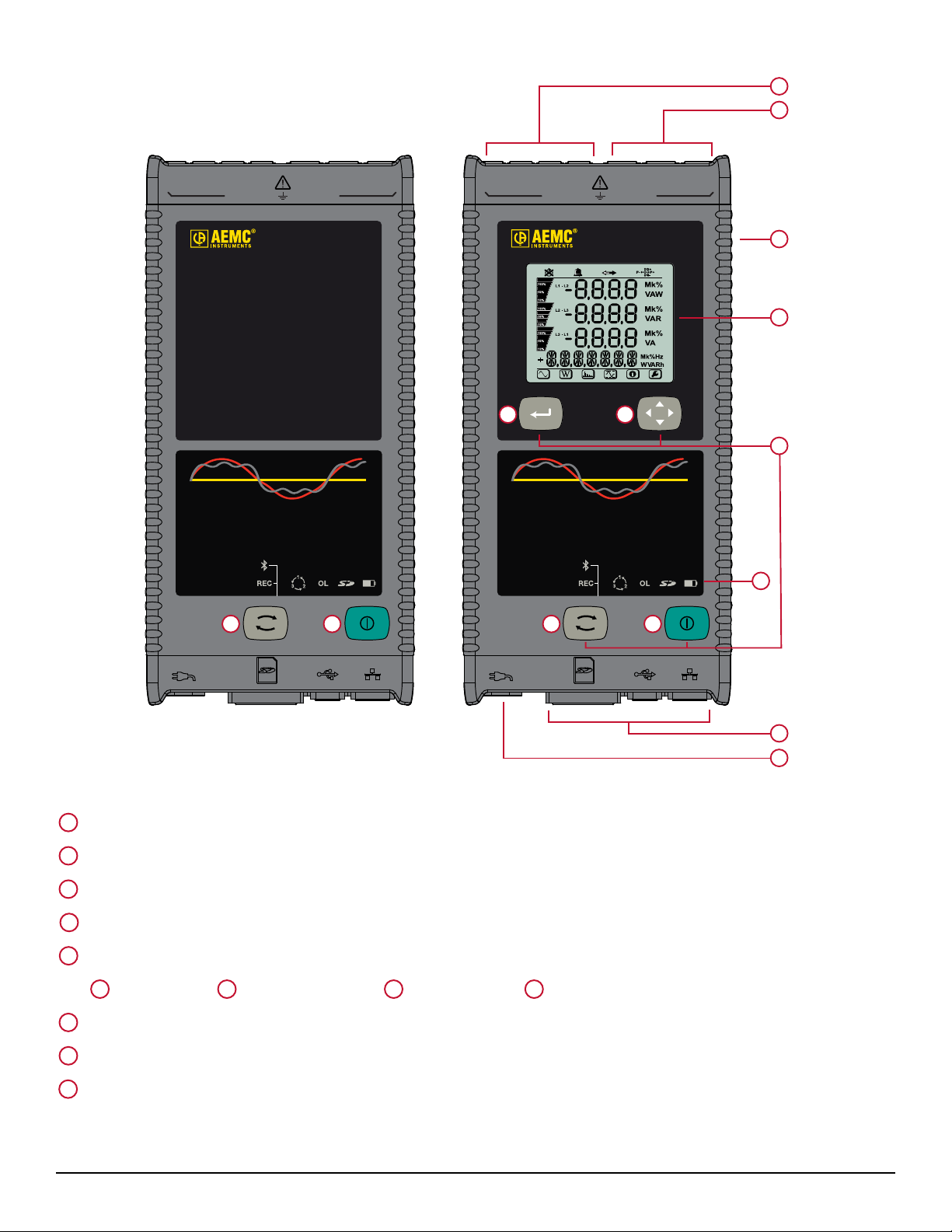
2.2 Front Panel Features
8
1
2
V1 V2 V3 N
1000V CAT III 600V CAT IV
POWER & ENERGY LOGGER
ON /OFF
START/STOP
C
I1 I2 I3 V1 V2 V3 N
MODEL PEL 102
1000V CAT III 600V CAT IV
A
POWER & ENERGY LOGGER
ON /OFF
START/STOP
D
C
I1 I2 I3
MODEL PEL 103
B
D
3
4
5
6
Figure 1
1
Four voltage input terminals.
2
Three current input terminals.
3
Rigid molded casing over-molded with thermo-adhesive rubber.
4
Digital LCD displaying measured, calculated and parameterizing quantities (see § 2.9).
5
Two (PEL 102) or Four (PEL 103) function buttons (see § 2.8).
A
Power & Energy Logger Model PEL 102 and PEL 103
Enter Button B Navigation Button
6
Nine LEDs for status information (see § 2.10).
7
Connections for USB, Ethernet, SD memory card and terminal cover caps.
8
Standard (IEC C7 gure 8 terminal – non polarized) power connector for 110/250VAC power source.
C
Control button D On/Off button
7
9
Page 12

2.3 Back Panel Features
WARNING!
Disconnect all inputs
before opening the
battery compartment
Only replace with 8.4V
NiMH custom battery pack
Power Supply:
110-250V DC/AC 50/60Hz 30VA
MADE IN FRANCE
1
2
Figure 2
1
Four magnets (molded into the rubber casing).
2
Six recessed Torx® screws (for factory service use only).
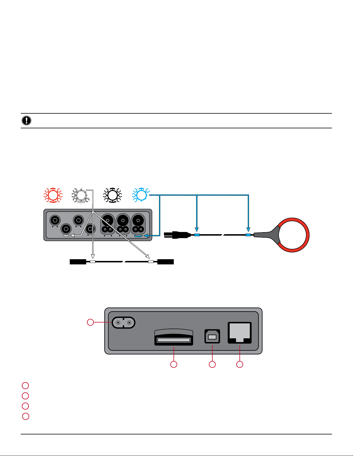
2.4 Lead Inputs
2
1
Figure 3
1
(• •) are the color-coded ID marker insertion locations for the current or voltage inputs.
2
Voltage input connectors (safety banana plug inputs).
3
Current sensor input connectors.
3
10
Power & Energy Logger Model PEL 102 and PEL 103
Page 13
For multiple-phase measurements, start by marking the accessories using the color-coded ID markers supplied with the
device; a different color for each current terminal.
Connect the measuring leads to your PEL as follows:
■ Current measurement: I1, I2, I3 4-point connectors
■ Voltage measurement: V1, V2, V3 and N terminals
The measuring leads must be connected to the circuit to be monitored according to the selected hook-up diagram. Do not
forget to dene the voltage and current transformer’s ratios when necessary.
2.5 Installation of the Color-coded ID Markers
Refer to the current sensor’s safety sheet or user manual before connecting it.
Twelve sets of color-coded rings and inserts are supplied with your PEL instrument. Use these ID markers to identify the
leads and input terminals.
■ Detach the appropriate inserts from the color-coded marker and place them in the holes provided under the
terminals (larger inserts for current terminals, smaller inserts for voltage terminals).
■ Clip the rings of the same color to the ends of the lead you will be connecting to the terminal.
2.6 Connection Features
1
1
Power cord connection (see § 3.5.1).
2
SD card slot (see § 3.5.3).
3
USB connector (see § 3.5.4).
4
Ethernet RJ 45 connector (see § 3.5.5).
Power & Energy Logger Model PEL 102 and PEL 103
Figure 4
2 3 4
Figure 5
11
Page 14
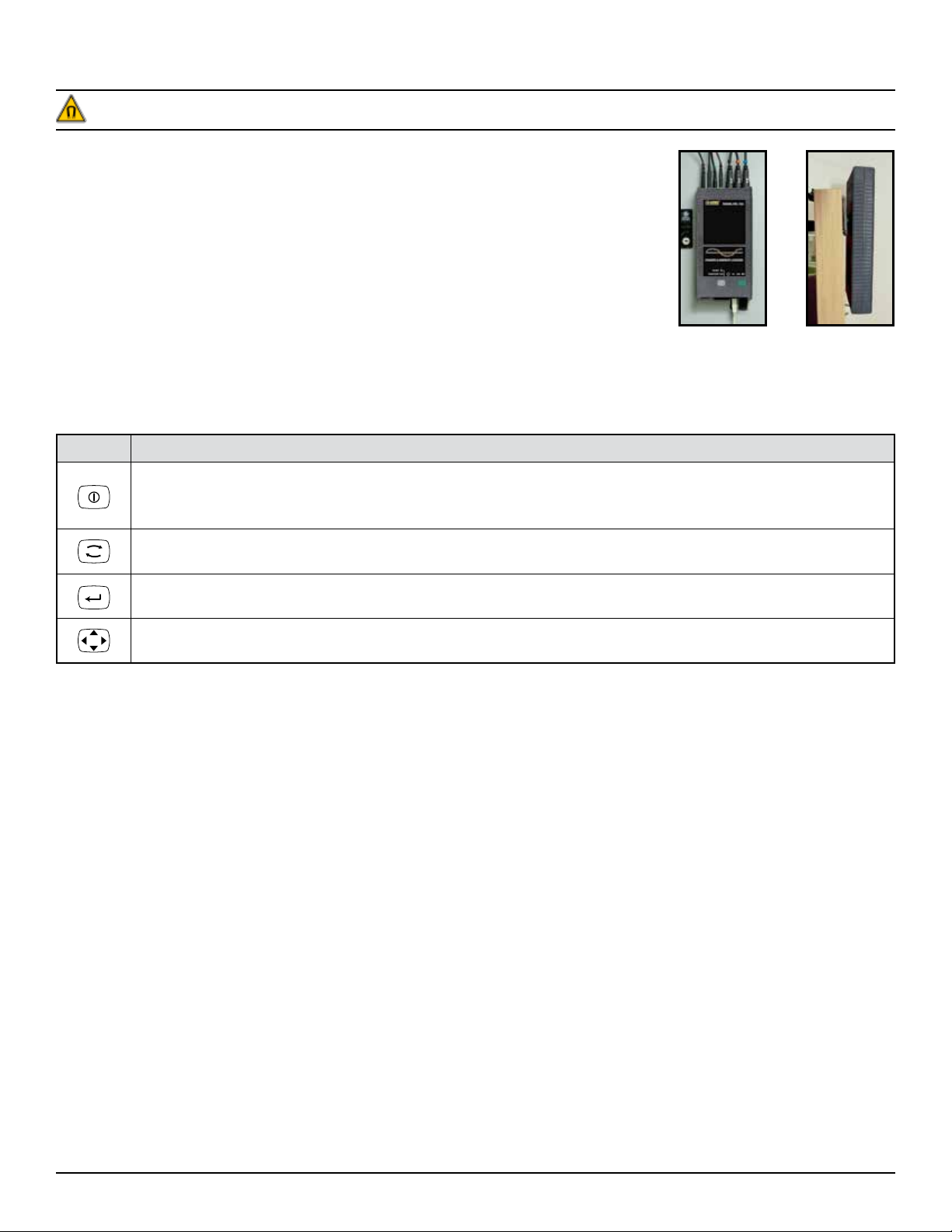
2.7 Mounting and Location
NOTE: Magnetic fields can damage hard drives and medical devices.
The PEL should be placed in a well-ventilated room; temperature not to exceed
those specied in § 5.6.
The PEL 102 and PEL 103 can be mounted to a at ferromagnetic vertical surface
using the molded-in magnets.
2.8 Button Functions
Figure 6
BUTTON
DESCRIPTION
ON/OFF Button:
- Turns the instrument ON or OFF (see § 3.1).
NOTE: The instrument cannot be turned OFF while connected to an AC outlet or if a recording is in progress.
Control Button:
- Starts/Stops the recording session and Enables/Disables Bluetooth (see § 3.4).
Enter Button (PEL103):
- Displays phase angle values and partial energies (long push) (see § 3.7.2)
Navigation Button (PEL103):
- Enables browsing and the selection of data displayed on the LCD (see § 3.7).
Table 1
12
Power & Energy Logger Model PEL 102 and PEL 103
Page 15
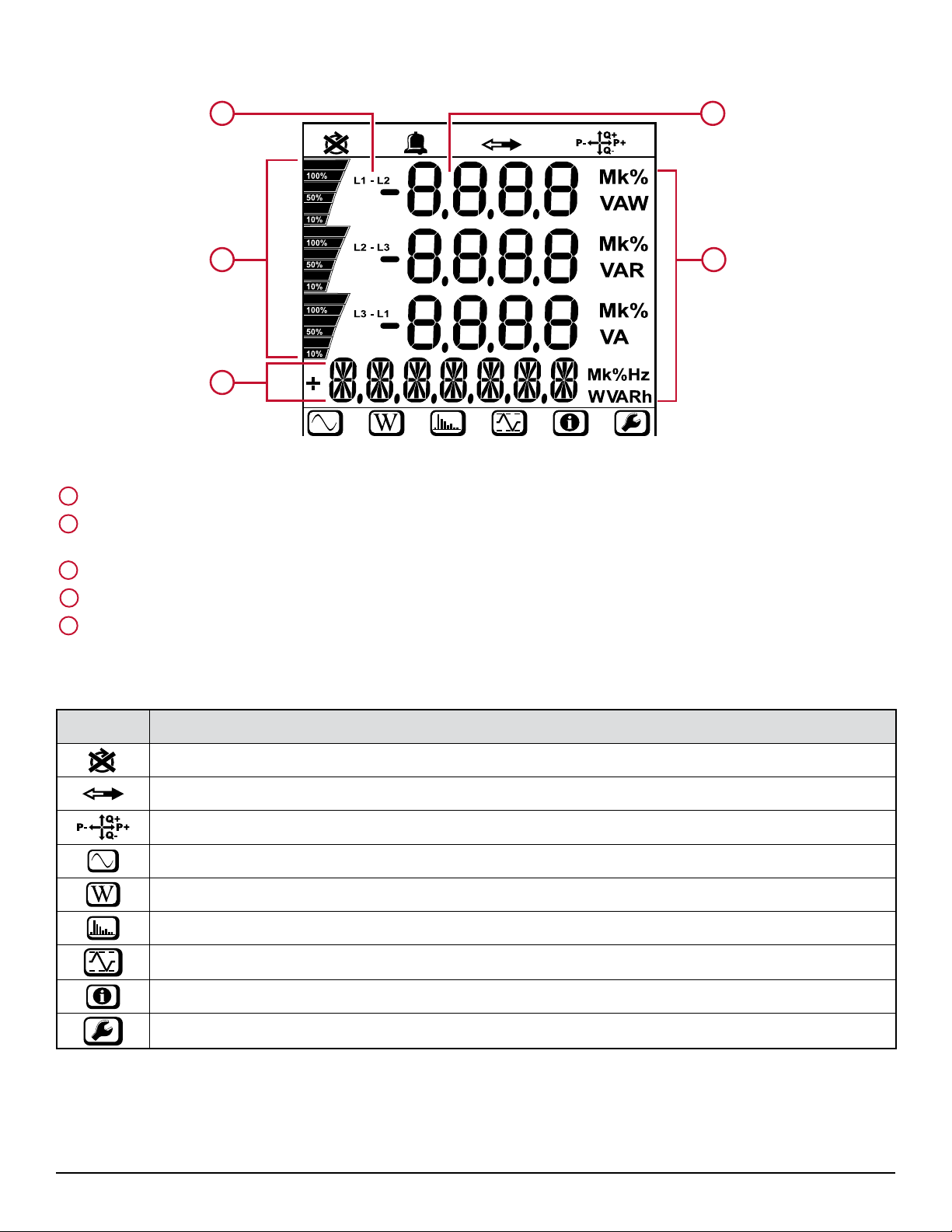
2.9 LCD Display (PEL 103)
1 4
2
5
3
Figure 7
1
Measured phase indicator.
2
Bargraph (Load factor - Min - Max). The bargraph indicates the percentage (0% to 100%) of full range or full load as
programmed into the PEL by the user through the DataView® software.
3
Measurements or page title.
4
Measurement values.
5
Measurement units.
Top and bottom display bars indicate the following:
ICON
DESCRIPTION
Phase Sequence reversal indicator or missing phase (displayed only in Real-Time Measurement Mode)
Data are available for recording (non-display indicates possible internal problem)
Power quadrant indicator
Real-time Measurement Mode
Power and Energy Mode
Harmonics Mode
Max Mode
Information Mode
Configuration Mode
Table 2
Power & Energy Logger Model PEL 102 and PEL 103
13
Page 16
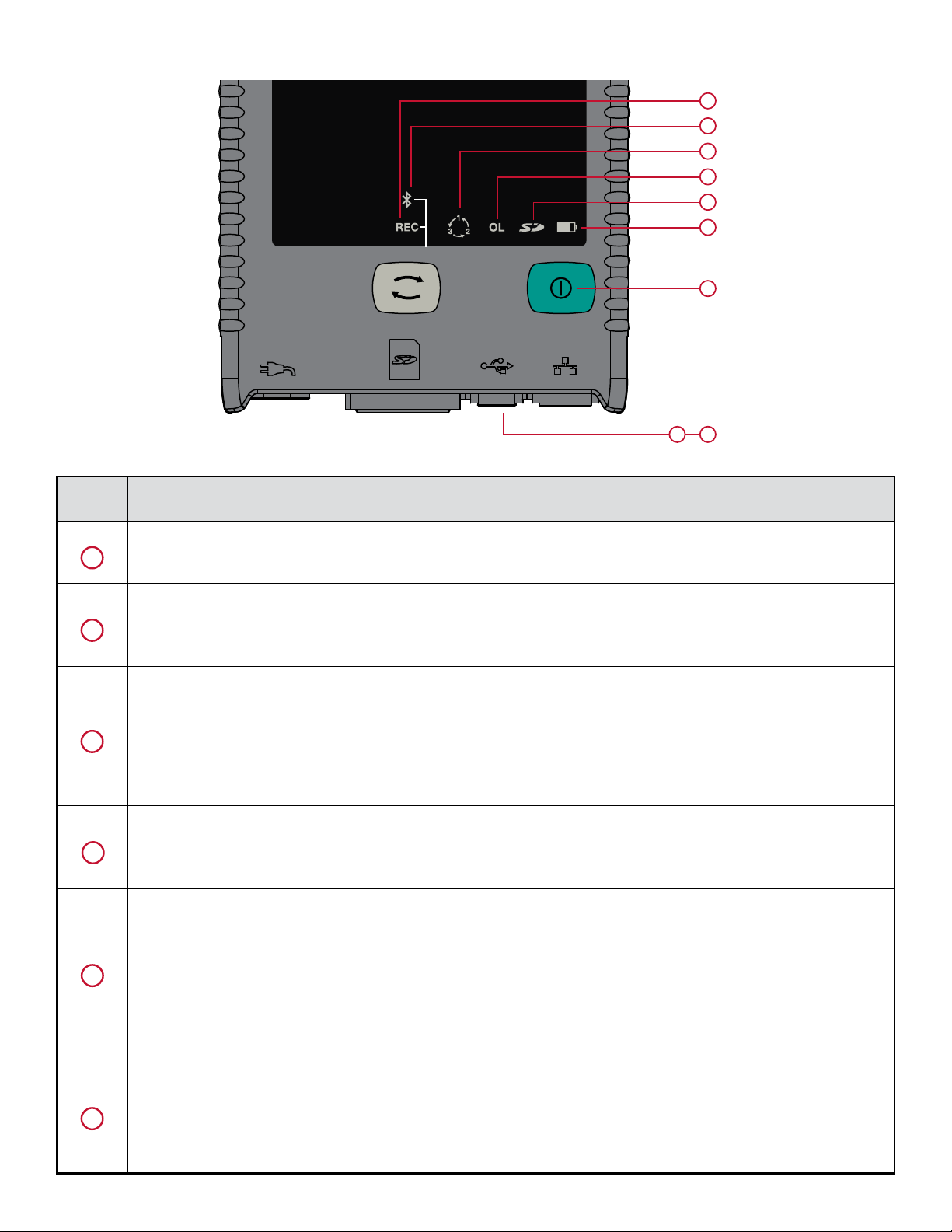
2.10 LED Status
3
ON /OFF
START/ STOP
1
2
3
4
5
6
7
8 9
Figure 8
LED &
COLOR
14
STATUS
Green LED: Recording Status
1
2
4
5
6
- LED blinks once per second every 5 s: Logger in standby (not recording)
- LED blinks twice per second every 5 s: Logger in recording mode
Blue LED: Bluetooth
- LED OFF: Bluetooth OFF (disabled)
- LED ON: Bluetooth ON (enabled - not transmitting)
- LED blinks twice per second: Bluetooth ON (enabled - transmitting)
Red LED: Phase Order
- OFF: Phase rotation order correct
- LED blinks once per second: the order of phase rotation is incorrect. In this case, there are three possibilities:
■ phase difference between the phase currents is 30° greater than normal (120° in three-phase and 180° in two-
phase).
■ phase difference between the phase voltages is 10° greater than normal.
■ phase difference between the currents and voltages of each phase is 60° greater than 0° (load) or 180° (source).
Red LED: Overload
- OFF: No input overload
- LED blinks once per second: At least one input is in overload
- LED ON: Indicates a current probe is either mismatched or missing
Red/Green LED: SD-Card Status
- Green LED ON: SD-Card is OK
- Red LED blinks ve times every 5 s: SD-Card is full
- Red LED blinks four times every 5 s: less than 1 week capacity remaining
- Red LED blinks three times every 5 s: less than 2 weeks capacity remaining
- Red LED blinks twice every 5 s: less than 3 weeks capacity remaining
- Red LED blinks once every 5 s: less than 4 weeks capacity remaining
- Red LED ON: SD-Card is not present or locked
Yellow/Red LED: Battery Status
- When the AC power cord is connected, the battery charges until it is full.
- LED OFF: Battery full (with or without power supply)
- Yellow LED ON: Battery is charging
- Yellow LED blinks once per second: Battery is recovering from a full discharge
- Red LED blinks twice per second: Low battery (and no power supply)
Power & Energy Logger Model PEL 102 and PEL 103
Page 17
LED &
9
COLOR
7
under
ON/OFF
button
STATUS
Green LED: ON/OFF
- LED ON: External power supply present
- LED OFF: No external power supply
8
embedded
in
the connec-
tor
embedded
in
the connec-
tor
Green LED: Ethernet
- LED OFF: No activity
- LED blinking: Activity
Yellow LED: Ethernet
- LED OFF: The stack failed to initialize or the Ethernet controller failed to initialize
- Blink Slow, toggle every second: The stack initialized properly
- Blink Fast, toggle 10 times per second: The Ethernet controller initialized properly
- Blink Twice, toggle 2 times, then pause: DHCP Error
- LED ON: Network initialized and ready for use
Table 3
2.11 Memory Capacity
The PEL accepts FAT32 formatted SDHC cards up to 32 GB in size. This much data can require a lot of demand on
a computer and a long download time (depending on the performance of the PC and connection type being used).
Furthermore, some computers may have problems handling such a large amount of data and spreadsheets can only
accept a limited amount of data.
Recording rates for the different types of session data are as follows:
■ 1s Harmonics: 83 MB per day.
■ 1s Trends: 17 MB per day.
■ Aggregated data: 1.2 MB per day for 1 minute periods.
For longer periods, this rate is divided by the period in minutes.
Example: for an aggregation period of 10 minutes, the rate will be 0.12 MB per day.
We recommend managing the data on the SD card and only recording that which is needed. For reference purposes,
a 5 day recording, with a 15 minute demand interval and recording 1 second data and harmonics on a 3-phase 4-wire
network would consume approximately 530 MB of storage space. If harmonics are not needed and the recording of them
is disabled, the space requirement is reduced to about 87 MB.
The recommended maximum recording times are:
■ seven days when the recording includes the aggregated values, 1-second data, and harmonics.
■ one month when the recording includes the aggregated values and 1-second data but not the harmonics.
■ one year when the recording contains only the aggregated values.
Also avoid exceeding 32 recorded sessions on the SD card.
NOTE: For recordings with harmonics or with a duration longer than one week, please use class 4 or higher SDHC cards.
We recommend not downloading large sessions through Bluetooth as it will take a very long time. If a Bluetooth download
is required, consider not recording 1 second trends and harmonics. The same 30 day recording would be reduced to just
2.5 MB.
Downloading over USB and Ethernet may be acceptable depending on the session size and network speed. We recommend putting the SD card into your PC directly or with the external card reader for fastest download time.
Power & Energy Logger Model PEL 102 and PEL 103
15
Page 18
3. OPERATION
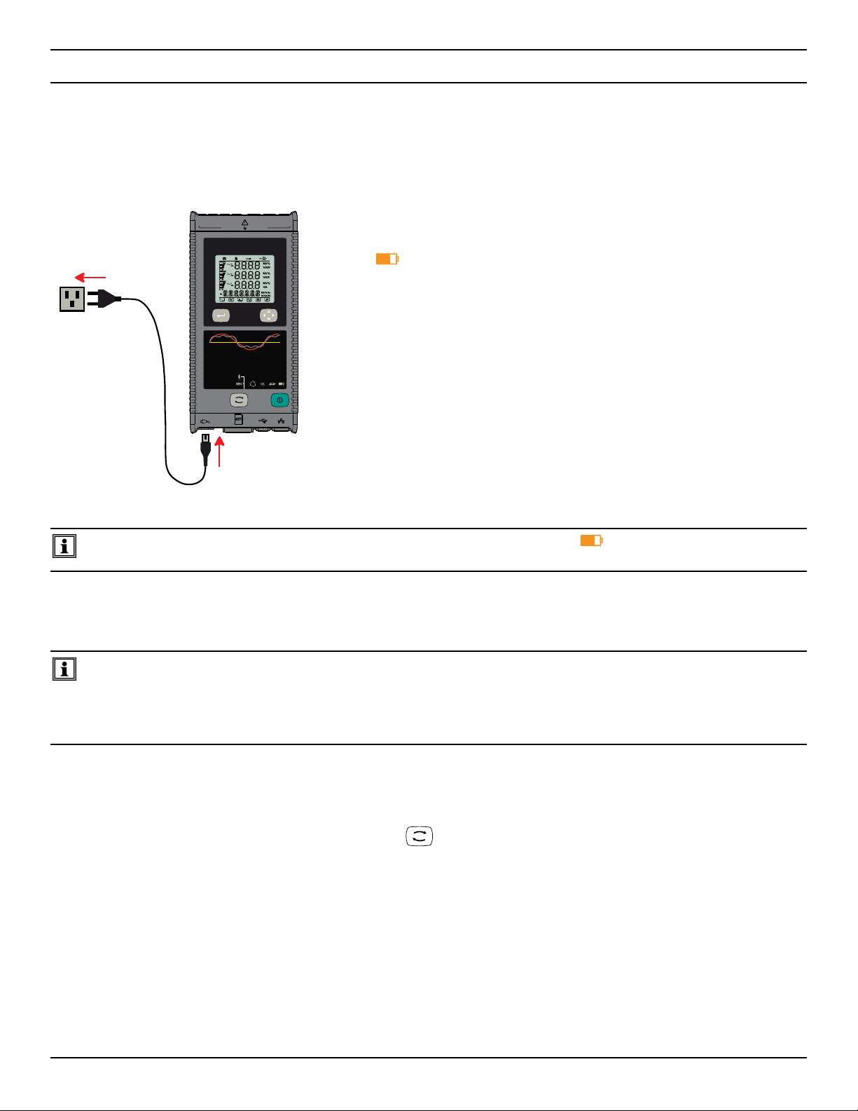
3.1 Charging the Battery
Before the first use, start by fully charging the battery.
■ Connect the supplied power cord to the instrument and AC power.
■ The device will automatically turn ON.
■ The LED lights; it will go out only when the battery is fully
120V ± 10%, 60Hz
230V ± 10%, 50Hz
V1 V2 V3 N
1000V CAT III 600V CAT IV
I1 I2 I3
charged.
■ A low battery charging takes approximately 5 hours.
The Yellow/Red LED (see #6 Figure 8) is used to indicate the status of the
POWER & ENERGY LOGGER
ON/OFF
START/STOP
battery.
■ When the power is on, the battery is charging until it is full.
■ LED OFF: Battery full (with or without power supply).
■ Yellow LED ON/No blinks: Battery is charging.
■ Yellow LED blinks twice per second: Battery is recovering after a full
discharge.
■ Red LED blinks twice per second: Low battery (and no power supply).
Figure 9
After prolonged storage, the battery may be completely discharged. If so, the LED blinks twice per second. In
this case, at least 5 charge/discharge cycles will be necessary for your battery to recover 95% of its capacity.
3.2 Operating the PEL
IMPORTANT: The following OPERATION instructions assume that the PEL has been configured by the user prior to
use. The PEL can only be fully configured through the PEL Control Panel distributed with the DataView® software,
although on the PEL 103 some parameters (such as hookup type) can also be set through the LCD display on the
device itself. Please refer to § 4.3 for setup instructions using DataView®, and § 3.7.6 for setup through the PEL 103
LCD display.
■ The PEL must be first programmed before recording. This is done through the PEL Control Panel (see § 4.3) or, for
the PEL 103, this can also be done on the LCD display (see § 3.7.6).
■ The PEL is then connected to a power supply and will turn on automatically (see § 3.3.1).
■ Recording is started by pressing the Control button
■ The PEL can be turned OFF when disconnected from the power supply (and when the recording session is
completed - see § 3.3.2).
(see § 3.4).
16
Power & Energy Logger Model PEL 102 and PEL 103
Page 19

3.3 Turning the Instrument ON/OFF
3.3.1 Turning the PEL ON
To turn the PEL ON:
■ Connect the PEL to a power outlet with the AC power cord and the PEL will turn ON automatically. If it does not,
press the ON/OFF button for >2 seconds.
■ The GREEN LED under the ON/OFF button turns ON when the PEL is connected to a live supply source.
NOTE: The batteries automatically begin recharging when the PEL is connected to a live power outlet. Battery life
is limited to approximately 1/2 hour when the battery is completely charged. This enables ride through during brief
power outages and power shutdowns.
3.3.2 Turning the PEL OFF
The PEL will not turn OFF as long as it is connected to a power supply source and if a recording is ON.
NOTE: This is done as a precaution to ensure that the PEL is not accidently turned OFF when recording and to ensure that
the PEL turns on when the power supply is turned back on after an outage.
To turn the PEL OFF:
■ Unplug the AC power supply outlet.
■ Press the ON/OFF button for more than 2 seconds until all LEDs turn on. Then release the ON/OFF button.
■ All LEDs and the display will turn off as the PEL powers down.
■ If the PEL has supply power present it will not turn OFF.
■ If a recording is pending or in progress it will not turn OFF.
NOTE: Pressing the ON/OFF button when the instrument is powered and/or recording (or pending) does not stop
the instrument. This is done to avoid any accidental or unintentional recording stoppage by the user. You must first
unplug the power cord from the supply outlet, stop any recording session, power down by pushing the ON/OFF
button for more than 2 seconds until all LEDs light up and then release the ON/OFF button.
Power & Energy Logger Model PEL 102 and PEL 103
17
Page 20

3.4 Starting/Stopping a Recording and Enabling Bluetooth
Recordings are stored only on the SD card.
To Start a Recording:
■ Insert the SD-card into the PEL.
■ Use the Control button
■ Press the Control button for more than 2 seconds and hold it down.
■ The green REC LED (see #1 Figure 8) will light up for 3 seconds, followed by the lighting of the blue Bluetooth
LED (see #2 Figure 8) for 3s - one after another. During the time these LEDs are lit, you will be able to control their
respective function as described below.
■ Releasing the Control button during (and only during) the 3 seconds lighting of a particular LED performs the
associated function:
■ REC LED (START/STOP)
- A release while LED is lit starts a recording (if recording is OFF)
- A release while LED is lit stops a recording (if recording is ON)
■ BLUETOOTH LED (ON/OFF)
- A release while LED is lit turns ON Bluetooth (if Bluetooth is OFF)
- A release while LED is lit turns OFF Bluetooth (if Bluetooth is ON)
If you want to make changes to both the Recording and Bluetooth, you need to go through the process twice.
to start or stop a recording session and to enable or disable Bluetooth.
NOTE: If the Control button is locked (disabled) by the PEL Control Panel (see § 4), you cannot use it to start
or stop a recording, or enable/disable Bluetooth. Instead, upon pressing the Control button while it is locked
you will see the Bluetooth and REC lights blink twice, with no changes taking effect on the instrument. To enable
the Control button, you must open the PEL Control Panel on your PC and de-select the “Lock out the Control
button…” option in the Configure Instrument dialog box, as explained in the PEL Control Panel online Help.
3.5 Connections
3.5.1 Power Supply
The PEL is powered by standard AC power through an external C7 cord (gure-eight type, non-polarized power plug).
This power cord is available in many computer or electrical supply stores. It is also referred to as a Laptop or Netbook C7
power cable. For replacement, be sure to buy the non-polarized cord. Replacement power cords are also available from
the factory.
The PEL can be supplied from nominal 110V to 250V (accepts ±10%) 50/60Hz to accommodate available supply voltages
globally.
NOTE: Never use power cords with inadequate rating.
■ When the instrument is powered by AC power, the instrument is always ON.
■ Applying AC power to the PEL turns the instrument ON if it was OFF and starts recharging the batteries
automatically.
■ When AC power is not present (power supply OFF or disconnected from a power supply), the instrument will run
on battery power for approximately 30 minutes or less when Auto Power Off is enabled (see below).
■ The PEL has a built in Auto Power OFF, which can be set to 3 to 15 min or disabled.
■ When the battery level is too low and a Low Bat condition occurs (the red LED blinks twice per second), the
instrument will eventually turn OFF. The PEL will start up again once it has been reconnected to a power supply.
18
Power & Energy Logger Model PEL 102 and PEL 103
Page 21

■ When the instrument is not powered by AC power, it can be turned ON with the ON/OFF button (see § 3.3.1).
■ When the instrument is not powered by AC power and no recording is pending or in progress, it can be turned
OFF with the ON/OFF button (see § 3.3.2).
3.5.2 Standby Mode (and Display Brightness)
When the instrument is ON and there is no activity for a denite time period, the LCD (PEL 103) automatically goes into
Standby mode.
The measurements and recording stay active, but the LCD backlight brightness diminishes to a user preset level. The
Standby LCD brightness level is user programmed through the PEL Control Panel (see § 4.4.1).
To re-establish the LCD Brightness, press the Enter or Navigation buttons.
Note that the overall display brightness is also programmed through the PEL Control Panel (see § 4.4.1).
3.5.3 Memory Card (SD-Card)
The PEL 102 and PEL 103 use an SD card for data storage. SD-Cards (up to 2 GB) and SDHC-Cards (4 GB up to 32 GB)
formatted FAT32 are supported. The PEL is delivered with a formatted SD card in the instrument. If you want to install a
new SD card, you must format the card before use.
■ Formatting the SD-Card is possible through the PEL DataView Control Panel when connected to the instrument
and if no recording is pending or in progress.
■ Hot extraction from the PEL is possible when no recording is in progress.
■ PEL les use short names (8 characters), such as Ses00004.
3.5.4 USB Connection to the PEL
The PEL 102 and PEL 103 can be connected to a computer through a USB (type A/Type B connectors) to congure the
PEL, prepare a recording session (real-time connection) and download recording sessions.
NOTE: Connecting the USB between the PC and the PEL will not power the logger or recharge the batteries.
3.5.5 LAN Ethernet Connection to the PEL
A LAN connection can be used to view real-time data, instrument status, congure the PEL, setup and start a recording
session and download recorded sessions.
The PEL has an IP address. When configuring the PEL with the PEL Control Panel, if the checkbox next to “Enable DHCP”
is checked in the Communication tab of the Configure Instrument dialog box (see § 4.4.2), the instrument sends a request
to the network DHCP server to automatically obtain an IP address.
If for any reason the DHCP server is not available, after 60 seconds the PEL Control Panel will enter auto-IP mode, using
the default IP address 169.254.0.100 (the same IP address used when “Enable DHCP” is not selected). This auto-IP mode
is compatible with APIPA (Automatic Private IP Addressing). A cross-over cable may be needed in auto-IP mode.
The Internet Protocol used is UDP. Port 3041 is used by default, but it can be modified in the PEL Control Panel (see §
4.4.2) to allow multiple PC connections to multiple PEL instruments behind a router.
NOTE: The LAN parameters cannot be modified while connected over a LAN link. A USB connection must
be used to modify them.
Power & Energy Logger Model PEL 102 and PEL 103
19
Page 22
3.5.6 Bluetooth Connection to the PEL
The PEL 102 and PEL 103 are designed for a Bluetooth wireless connection to a computer. The Bluetooth connection can
be used to configure the PEL, to prepare a recording session and to download recorded sessions.
To communicate using the Bluetooth connection you will need a computer with Bluetooth capability. Some computers are
supplied with this capability, while others will need to have an external Bluetooth adapter.
The pairing procedure varies depending on your operating system, Bluetooth equipment and driver software.
The default pairing code is 0000 if needed. The pairing code cannot be modified through the PEL Control Panel (DataView®
software).
NOTE: The information in the following section is only necessary the first time an instrument is connected.
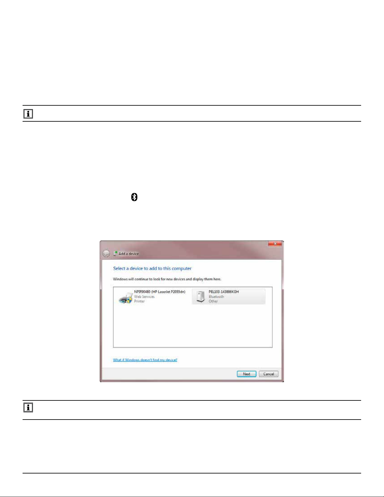
3.5.6.1 Pairing using Windows 7
The following example uses the Windows 7 operating system procedure. The pairing procedure for older versions of Win-
dows may vary.
1. First, make sure Bluetooth is enabled on the instrument (see § 4.4.2)
2. Connect the USB adapter to the PC.
3. A Bluetooth symbol, similar to this
, will appear in the taskbar (bottom-right side of your computer screen) once the
driver is installed.
4. Double-click on the icon and select “Add a Device”.
5. In the “Add a Device” window, select the PEL model you wish to connect to and select “Next”.
Figure 10
NOTE: Depending on the Bluetooth setup and operating systems, it may be necessary to enter a passkey to finalize
the instrument connection. If so, the default passkey is: 0000.
20
Power & Energy Logger Model PEL 102 and PEL 103
Page 23
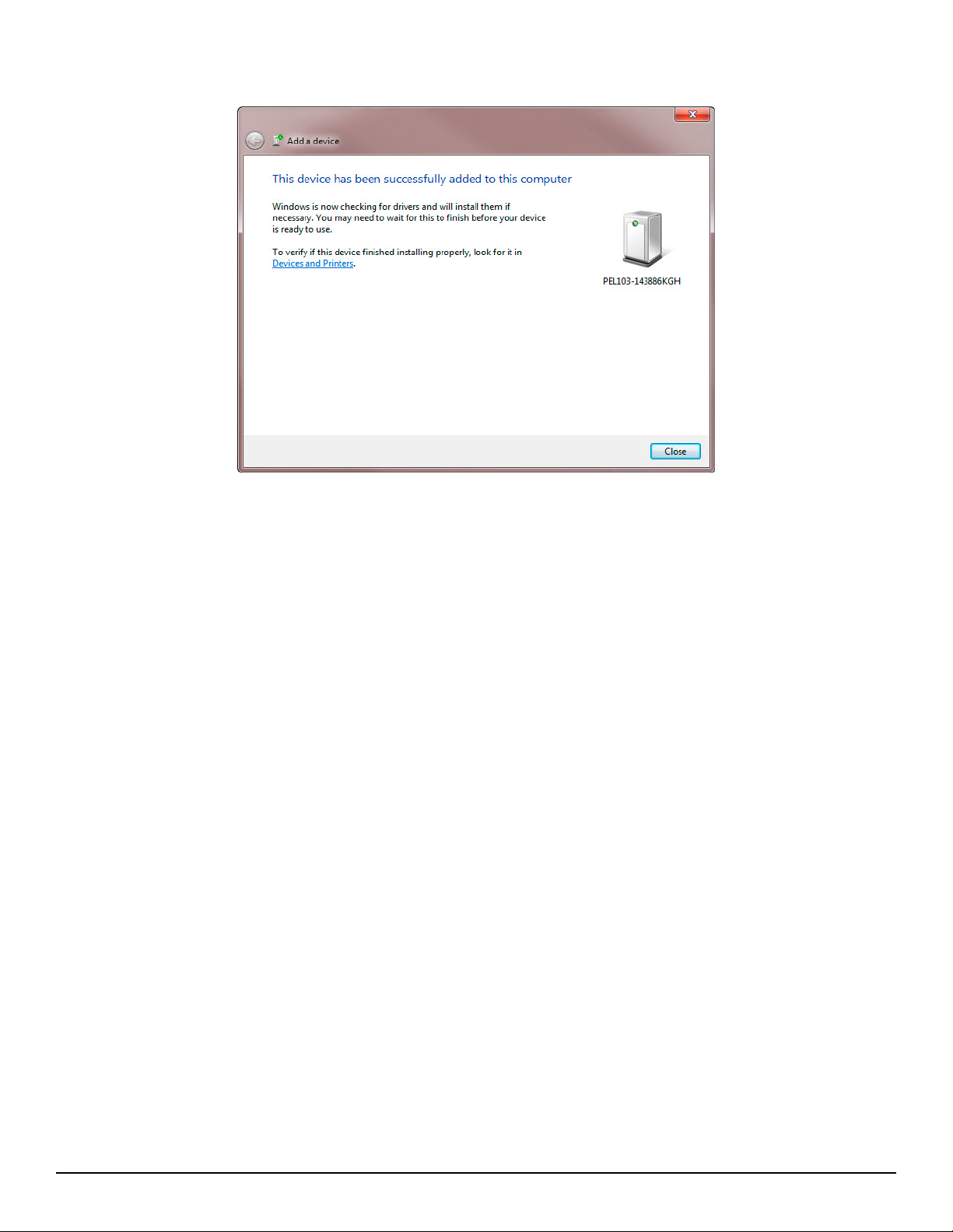
6. Once the instrument has been successfully added to the computer, a window similar to Figure 11 will be displayed.
Select “Close”.
Figure 11
7. Launch the PEL Control Panel using the icon placed on the desktop during the Dataview® software installation, then
connect the instrument via Bluetooth by performing the steps in §4.2.
Power & Energy Logger Model PEL 102 and PEL 103
21
Page 24
3.6 Distribution Systems and PEL Hook-ups
This section describes how the current sensors and voltage test leads have to be connected to your installation according
to its distribution system. The PEL shall also be congured (see § 4.4.3) for the selected distribution system.
Source Load
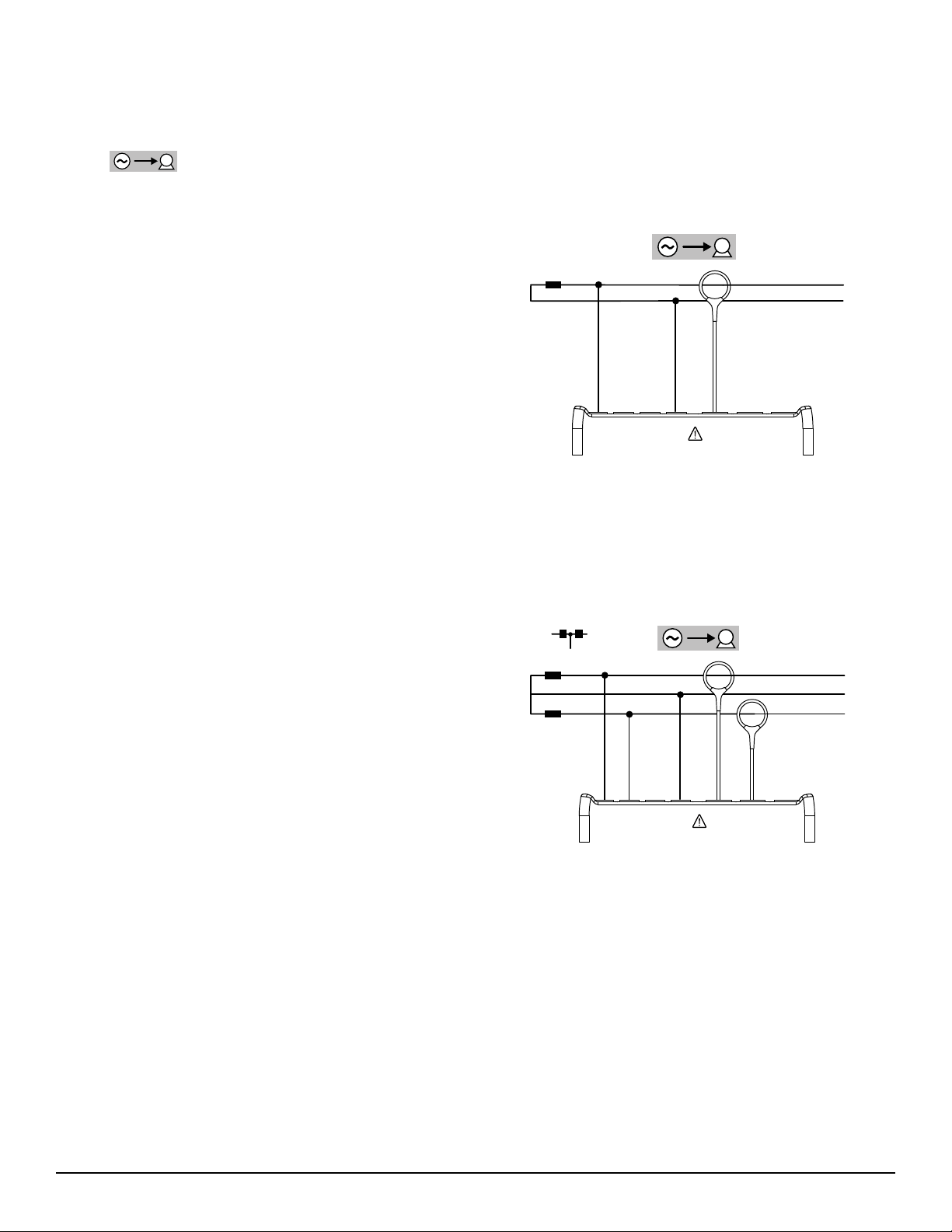
3.6.1 Single Phase 2-Wire
For Single Phase 2-Wire measurements:
■ Connect the terminal N test lead to the neutral conductor
■ Connect the terminal V1 test lead to the L1 phase conductor
■ Connect the current probe to the L1 phase conductor
Ensure that the current arrow on the sensor is directed towards the
load. This ensures proper phase angle for power measurements
and other phase sensitive measurements.
V1 V2 V3 N I1 I2 I3
3.6.2 Single Phase 3-Wire (Split Phase from a center tap transformer)
L1
N
Figure 12
For Single Phase 3-Wire (Split Phase) measurements:
■ Connect the terminal N test lead to the neutral conductor
■ Connect the terminal V1 test lead to the L1 phase conductor
■ Connect the terminal V2 test lead to the L2 phase conductor
■ Connect the terminal I1 current probe to the LI phase
conductor
■ Connect the terminal I2 current probe to the L2 phase
conductor
Ensure that the current arrow on the sensor is directed towards the
load. This ensures proper phase angle for power measurements and
other phase sensitive measurements.
L2 L1
N
L1
N
L2
V1 V2 V3 N I1 I2 I3
Figure 13
22
Power & Energy Logger Model PEL 102 and PEL 103
Page 25
3.6.3 3-Phase 3-Wire Power Networks
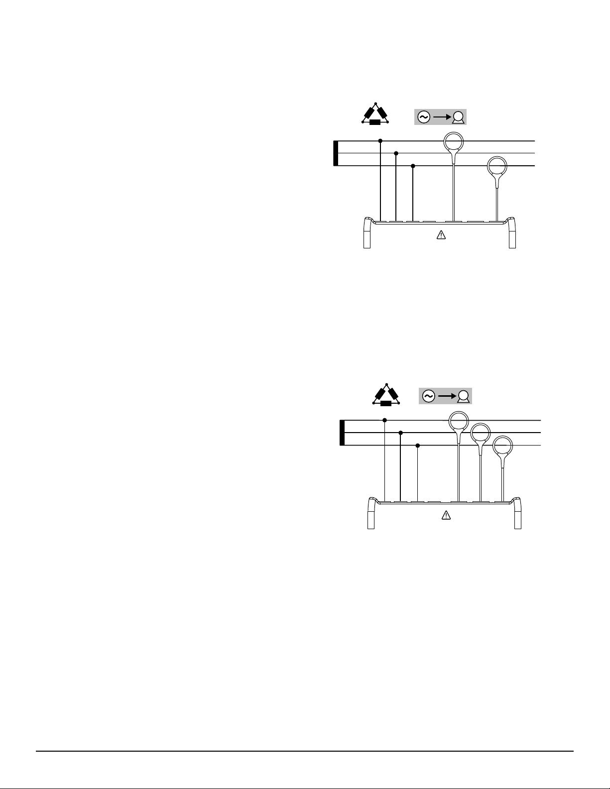
3.6.3.1 3-Phase 3-Wire ∆ (with 2 current sensors)
For 3-Phase 3-Wire
∆ measurements using two current sensors:
■ Connect the terminal V1 test lead to the L1 phase
conductor
■ Connect the terminal V2 test lead to the L2 phase
conductor
■ Connect the terminal V3 test lead to the L3 phase
conductor
■ Connect the terminal I1 current probe to the LI phase
conductor
■ Connect the terminal I3 current probe to the L3 phase
conductor
Ensure that the current arrow on the sensor is directed towards
the load. This ensures proper phase angle for power measurements and other phase sensitive measurements.
3.6.3.2 3-Phase 3-Wire ∆ (with 3 current sensors)
For 3-Phase 3-Wire
∆ measurements using three current sensors:
L3
L2 L
1
V1 V2 V3 N I1 I2 I3
Figure 14
L3
L1
L2
L3
■ Connect the terminal V1 test lead to the L1 phase conductor
■ Connect the terminal V2 test lead to the L2 phase conductor
■ Connect the terminal V3 test lead to the L3 phase conductor
■ Connect the terminal I1 current probe to the LI phase
conductor.
■ Connect the terminal I2 current probe to the L2 phase
conductor
■ Connect the terminal I3 current probe to the L3 phase
conductor
Ensure that the current arrow on the sensor is directed towards the
load. This ensures proper phase angle for power measurements
and other phase sensitive measurements.
L2 L
1
V1 V2 V3 N I1 I2 I3
Figure 15
L1
L2
L3
Power & Energy Logger Model PEL 102 and PEL 103
23
Page 26
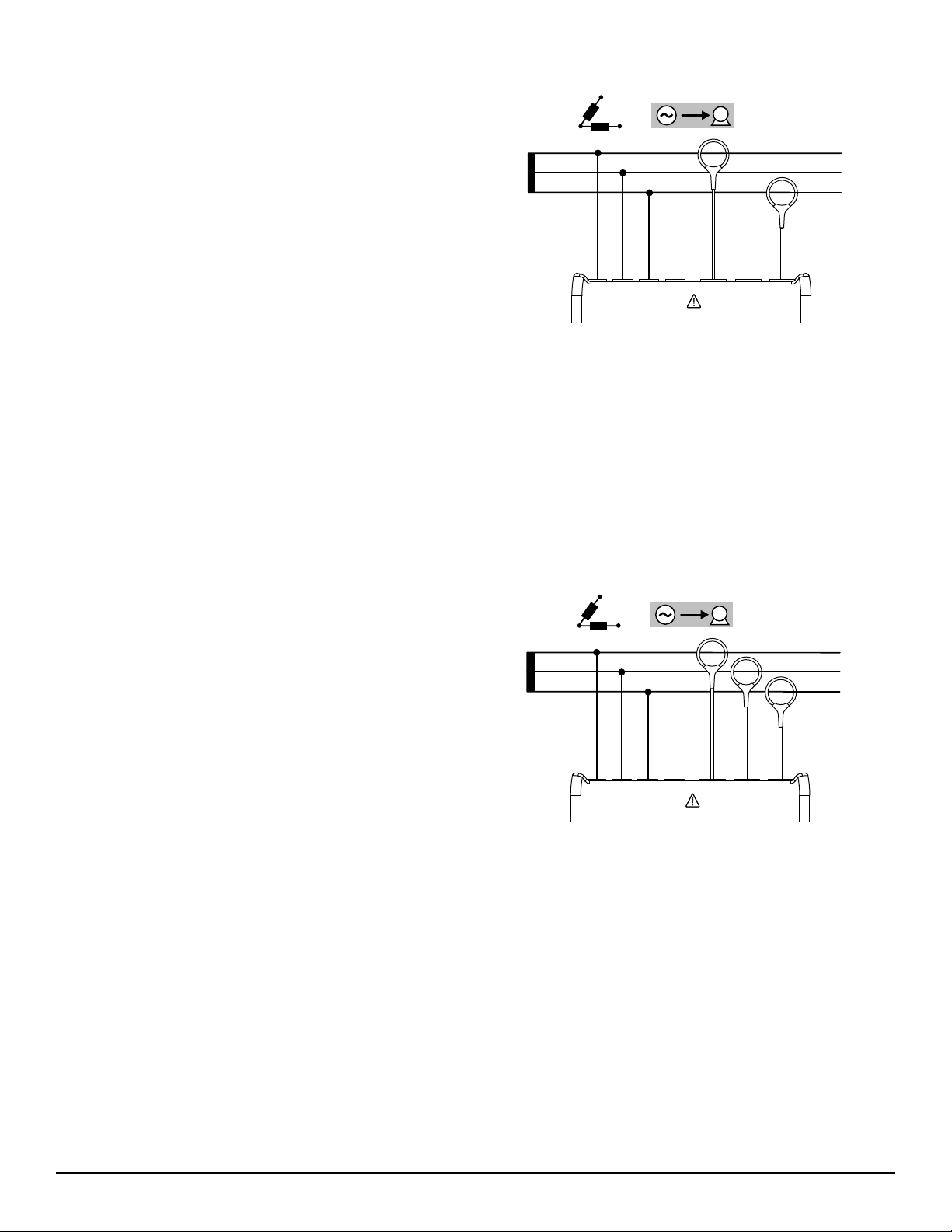
3.6.3.3 3-Phase 3-Wire Open ∆ (with 2 current sensors)
For 3-Phase 3-Wire Open
∆ measurements using two current
sensors:
■ Connect the terminal V1 test lead to the L1 phase
conductor
■ Connect the terminal V2 test lead to the L2 phase
conductor
■ Connect the terminal V3 test lead to the L3 phase
conductor
■ Connect the terminal I1 current probe to the LI phase
conductor
■ Connect the terminal I3 current probe to the L3 phase
conductor
Ensure that the current arrow on the sensor is directed towards
the load. This ensures proper phase angle for power measurements and other phase sensitive measurements.
L3
L2 L
1
V1 V2 V3 N I1 I2 I3
Figure 16
L1
L2
L3
3.6.3.4 3-Phase 3-Wire Open ∆ (with 3 current sensors]
For 3-Phase 3-Wire Open
∆ measurements using three current
sensors:
■ Connect the terminal V1 test lead to the L1 phase
conductor
■ Connect the terminal V2 test lead to the L2 phase
conductor
■ Connect the terminal V3 test lead to the L3 phase
conductor
■ Connect the terminal I1 current probe to the LI phase
conductor
■ Connect the terminal I2 current probe to the L2 phase
conductor
■ Connect the terminal I3 current probe to the L3 phase
conductor
Ensure that the current arrow on the sensor is directed towards
the load. This ensures proper phase angle for power measurements and other phase sensitive measurements.
L3
L2 L
1
V1 V2 V3 N I1 I2 I3
Figure 17
L1
L2
L3
24
Power & Energy Logger Model PEL 102 and PEL 103
Page 27
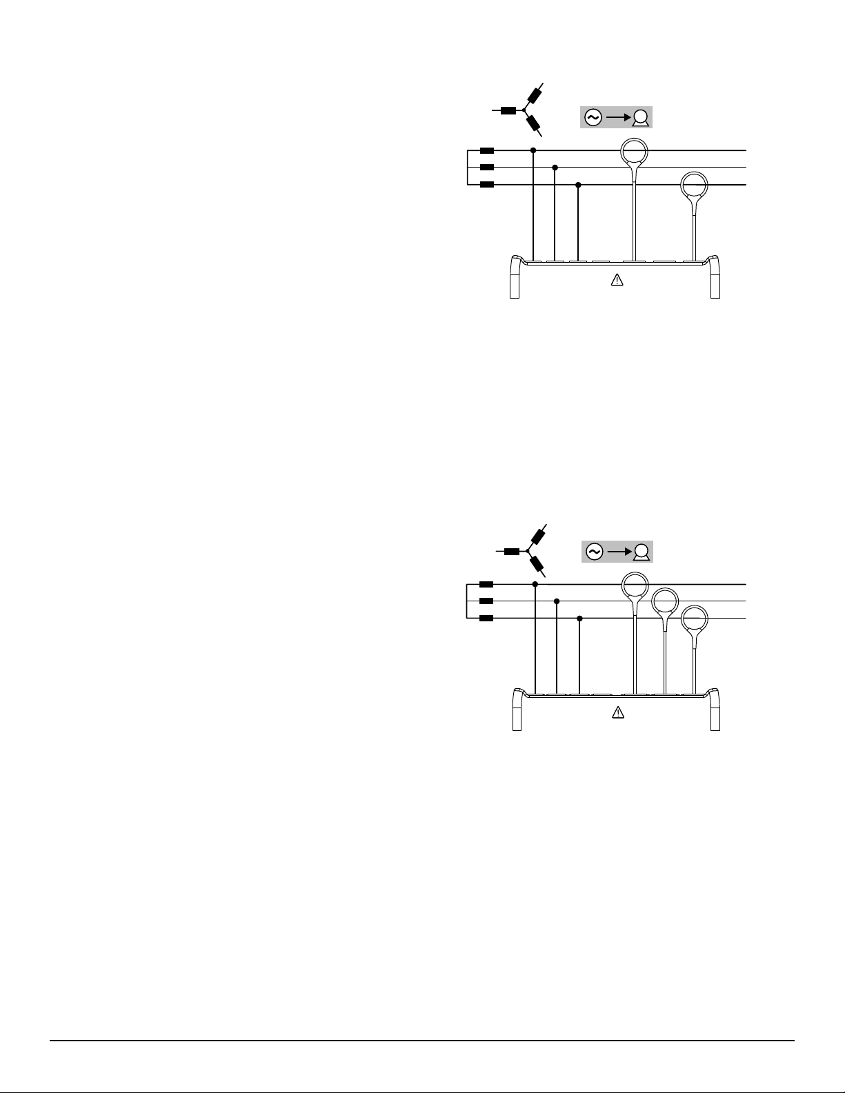
3.6.3.5 3-Phase 3-Wire Y (with 2 current sensors)
For 3-Phase 3-Wire Y measurements using two current
sensors:
■ Connect the terminal V1 test lead to the L1 phase
conductor
■ Connect the terminal V2 test lead to the L2 phase
conductor
■ Connect the terminal V3 test lead to the L3 phase
conductor
■ Connect the terminal I1 current probe to the LI phase
conductor
■ Connect the terminal I3 current probe to the L3 phase
conductor
Ensure that the current arrow on the sensor is directed
towards the load. This ensures proper phase angle for power
measurements and other phase sensitive measurements.
L3
L2
N
L1
L1
L2
L3
V1 V2 V3 N I1 I2 I3
Figure 18
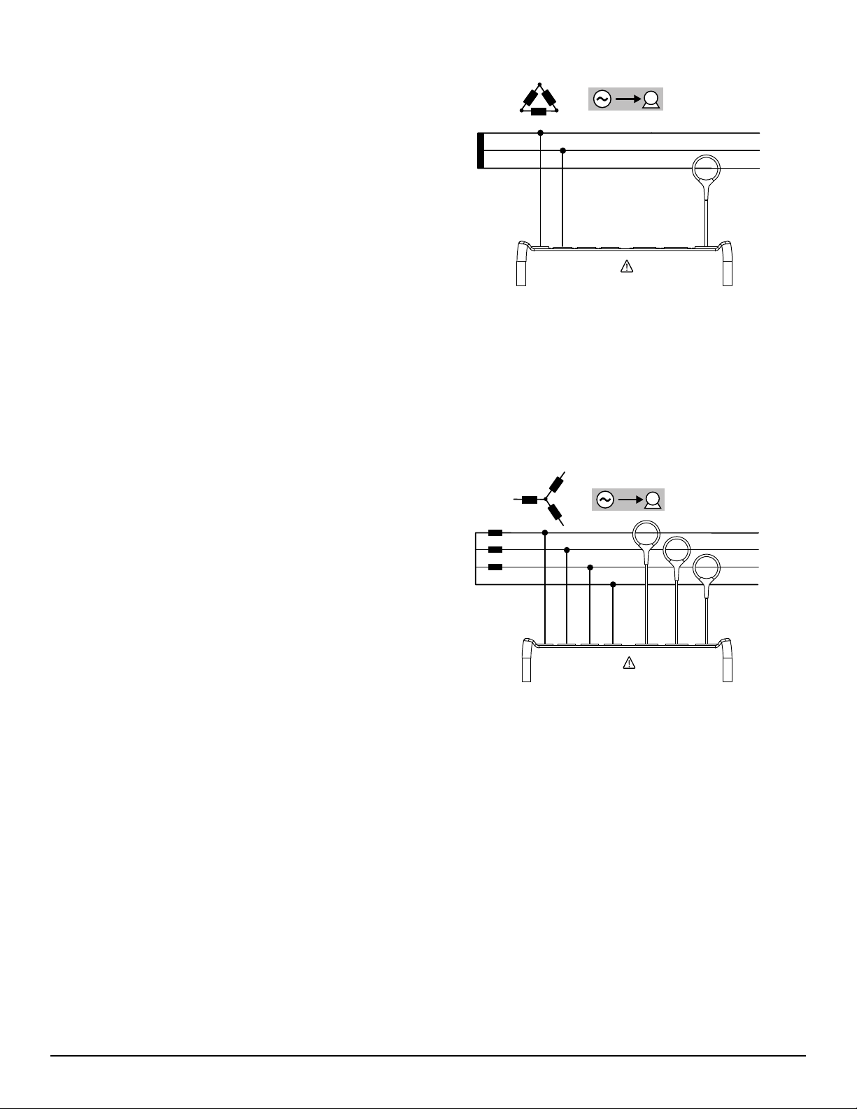
3.6.3.6 3-Phase 3-Wire Y (with 3 current sensors]
For 3-Phase 3-Wire Y measurements using three current
sensors:
■ Connect the terminal V1 test lead to the L1 phase
conductor
■ Connect the terminal V2 test lead to the L2 phase
conductor
■ Connect the terminal V3 test lead to the L3 phase
conductor
■ Connect the terminal I1 current probe to the LI phase
conductor
■ Connect the terminal I2 current probe to the L2 phase
conductor
■ Connect the terminal I3 current probe to the L3 phase
conductor
Ensure that the current arrow on the sensor is directed
towards the load. This ensures proper phase angle for power
measurements and other phase sensitive measurements.
L3
L2
N
L1
L1
L2
L3
V1 V2 V3 N I1 I2 I3
Figure 19
Power & Energy Logger Model PEL 102 and PEL 103
25
Page 28
3.6.3.7 3-Phase 3-Wire ∆ Balanced (with 1 current sensor)
For 3-Phase 3-Wire
∆ Balanced measurements using one
current sensor:
■ Connect the terminal V1 test lead to the L1 phase
conductor
■ Connect the terminal V2 test lead to the L2 phase
conductor
■ Connect the terminal I3 current probe to the L3 phase
conductor
Ensure that the current arrow on the sensor is directed
towards the load. This ensures proper phase angle for power
measurements and other phase sensitive measurements.
3.6.4 3-Phase 4-Wire Y Power Networks
3.6.4.1 3-Phase 4-Wire Y (with 3 current sensors)
For 3-Phase 4-Wire Y measurements using three current sensors:
■ Connect the terminal N test lead to the neutral conductor
■ Connect the terminal V1 test lead to the L1 phase conductor
■ Connect the terminal V2 test lead to the L2 phase conductor
■ Connect the terminal V3 test lead to the L3 phase conductor
L3
L2
L1
V1 V2 V3 N I1 I2 I3
Figure 20
L3
L2
N
L1
L1
L2
L3
L1
L2
L3
N
■ Connect the terminal I1 current probe to the LI phase
conductor
■ Connect the terminal I2 current probe to the L2 phase
conductor
■ Connect the terminal I3 current probe to the L3 phase
conductor
Ensure that the current arrow on the sensor is directed towards the
load. This ensures proper phase angle for power measurements
and other phase sensitive measurements.
V1 V2 V3 N I1 I2 I3
Figure 21
26
Power & Energy Logger Model PEL 102 and PEL 103
Page 29

3.6.4.2 3-Phase 4-Wire Y Balanced
L1
L2
L3
For 3-Phase 3-Wire Balanced Y measurements using one
current sensor:
■ Connect the terminal N test lead to the neutral conductor
■ Connect the terminal V1 test lead to the L1 phase
conductor
■ Connect the terminal I1 current probe to the L1 phase
conductor
Ensure that the current arrow on the sensor is directed towards
the load. This ensures proper phase angle for power measurements and other phase.
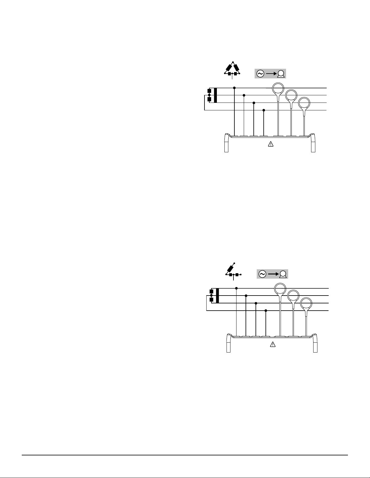
3.6.4.3 3-Phase 4-Wire Y 2½ Element
For 3-Phase 4-Wire Y 2½ Element measurements and using
three current sensors:
■ Connect the terminal N test lead to the neutral conductor
■ Connect the terminal V1 test lead to the L1 phase
conductor
■ Connect the terminal V3 test lead to the L3 phase
conductor
■ Connect the terminal I1 current probe to the LI phase
conductor
■ Connect the terminal I2 current probe to the L2 phase
conductor
■ Connect the terminal I3 current probe to the L3 phase
conductor
L3
L2
L2
N
L1
V1 V2 V3 N I1 I2 I3
Figure 22
L3
N
L1
V1 V2 V3 N I1 I2 I3
Figure 23
L1
L2
L3
N
N
Ensure that the current arrow on the sensor is directed towards
the load. This ensures proper phase angle for power measurements and other phase sensitive measurements.
Power & Energy Logger Model PEL 102 and PEL 103
27
Page 30
3.6.5 3-Phase 4-Wire ∆
High Leg configuration. No Potential Transformer (Voltage Transformer) is connected; the installation under test is supposed to be a low voltage distribution system.
3.6.5.1 3-Phase 4-Wire ∆
L2
For 3-Phase 4-Wire
sensors:
■ Connect the terminal N test lead to the neutral conductor
■ Connect the terminal V1 test lead to the L1 phase
conductor
■ Connect the terminal V2 test lead to the L2 phase
conductor
■ Connect the terminal V3 test lead to the L3 phase
conductor
■ Connect the terminal I1 current probe to the LI phase
conductor
■ Connect the terminal I2 current probe to the L2 phase
conductor
■ Connect the terminal I3 current probe to the L3 phase
conductor
∆ measurements and using three current
L1
L3
N
V1 V2 V3 N I1 I2 I3
Figure 24
L1
L2
L3
N
Ensure that the current arrow on the sensor is directed
towards the load. This ensures proper phase angle for power
measurements and other phase sensitive measurements.
3.6.5.2 3-Phase 4-Wire Open ∆
For 3-Phase 4-Wire Open
∆ measurements and using three cur-
rent sensors:
■ Connect the terminal N test lead to the neutral conductor
■ Connect the terminal V1 test lead to the L1 phase
conductor
■ Connect the terminal V2 test lead to the L2 phase
conductor
■ Connect the terminal V3 test lead to the L3 phase
conductor
■ Connect the terminal I1 current probe to the LI phase
conductor
■ Connect the terminal I2 current probe to the L2 phase
conductor
■ Connect the terminal I3 current probe to the L3 phase
conductor
L2
L1
L3
N
V1 V2 V3 N I1 I2 I3
Figure 25
L1
L2
L3
N
Ensure that the current arrow on the sensor is directed towards
the load. This ensures proper phase angle for power measurements and other phase sensitive measurements.
28
Power & Energy Logger Model PEL 102 and PEL 103
Page 31

3.6.6 DC Power Networks
+1
+2
3.6.6.1 DC 2-Wire
For DC 2- Wire measurements:
■ Connect the terminal N test lead to the common
conductor
■ Connect the terminal V1 test lead to conductor +1
■ Connect the terminal I1 current probe to conductor +1
Ensure that the current arrow on the sensor is directed towards
the load. This ensures proper measurements for power and
other sign sensitive quantities.
3.6.6.2 DC 3-Wire
For DC 3- Wire measurements:
■ Connect the terminal N test lead to the common conductor
■ Connect the terminal V1 test lead to conductor +1
■ Connect the terminal V2 test lead to conductor +2
■ Connect the terminal I1 current probe to conductor +1
+1
_
V1 V2 V3 N I1 I2 I3
Figure 26
_
■ Connect the terminal I2 current probe to conductor +2
Ensure that the current arrow on the sensor is directed towards the
load. This ensures proper measurements for power and other sign
sensitive quantities.
V1 V2 V3 N I1 I2 I3
Figure 27
Power & Energy Logger Model PEL 102 and PEL 103
29
Page 32

3.6.6.3 DC 4-Wire
For DC 4-Wire measurements and using three current sensors:
■ Connect the terminal N test lead to the common conductor
■ Connect the terminal V1 test lead to conductor +1
■ Connect the terminal V2 test lead to conductor +2
■ Connect the terminal V3 test lead to conductor +3
■ Connect the terminal I1 current probe to conductor +1
■ Connect the terminal I2 current probe to conductor +2
■ Connect the terminal I3 current probe to conductor +3
Ensure that the current arrow on the sensor is directed towards the
load. This ensures proper measurements for power and other sign
sensitive quantities.
+1
+2
+3
_
V1 V2 V3 N I1 I2 I3
Figure 28
30
Power & Energy Logger Model PEL 102 and PEL 103
Page 33

3.7 LCD Display Modes (PEL 103 Only)
The PEL 103 includes an LCD display that allows you to view a variety of measurement values and set-up parameters. The
display also lets you change several configuration settings.
NOTE: Although the PEL 103 LCD display allows you to enter a limited number of set-up values, the PEL can only be
fully configured through the PEL Control Panel (DataView® software). Note that the PEL 102 can only be congured
with the PEL Control Panel. For detailed instructions on configuring, recording and downloading measurements,
refer to § 4.
The ◄ and ► navigation buttons are used to scroll through the available modes LCD Display modes.
Five of these modes allow you to view several types of data:
(Base Measurements) displays the measurement values V, A, Power, Frequency, Power Factor, and Tanget Angle
(Energy) displays the energy values kWk, Vah, and Varh
(Harmonics) displays harmonics for current and voltage
(Max) displays the maximum values for the measurement, energy, and harmonic values
(Information) displays hook-up and system information
In addition:
(Configuration) allows you to enter several setup parameters, described later in this section.
3.7.1 Base Measurements - Displayed Values
The base measurements, or instantaneous readings, are displayed sequentially in screens showing all phases. The display
sequence varies per type of power network. Table 4 shows the readings per network.
To navigate through the displays, use the Navigation
■ Use the up and down arrows (▲ or ▼) on the Navigation button to step through the displays.
■ Use the Enter button to display additional information. Note that this does not advance the display to the next
step. Instead, a screen displayed by Enter can be considered a “sub step” in the display cycle.
■ To exit a display called up by Enter, press the Navigation button once. This returns you to the previous screen;
you can then use ▲ or ▼ to continue navigating through the displays.
■ To exit and move to a different display mode, press ◄ or ► on the Navigation button.
NOTE: In some distribution systems and steps, pressing Enter has no effect.
and Enter
buttons.
Power & Energy Logger Model PEL 102 and PEL 103
31
Page 34

Table 4 displays the LCD (PEL 103) sequence for each type of hook-up. The displays on the left show an example of a
3-Phase 4-Wire network type. The Step column shows which button to use to display the step, either ▼ to display a main
step or
to display a “sub step” (1a, 2a, and so on).
Step
1
◄ ►
1a
2
▼
1-Phase
2-Wire
P
I
V
F
ϕ (I1, V1)
« V-I ANGLE»
P
Q
S
«PF» PF
DC
2-Wire
P DC
I DC
V DC
1-Phase
3-Wire
I1
I2
F
ϕ (I2, I1)
«I ANGLE»
V1
V2
U12
DC
3-Wire
I1 DC
I2 DC
V1 DC
V2 DC
3-Phase
(*)
3-Wire
I1
I2
I3
ϕ (I2, I1)
ϕ (I3, I2)
ϕ (I1, I3)
«I ANGLE»
U12
U23
U31
F
3-Phase 3-Wire
Balanced
I3
I3
I3
U12
U12
U12
F
3-Phase
4-Wire
(3P-4WY;
3P-4WY2)
I1
I2
I3
«IN» IN
ϕ (I2, I1)
ϕ (I3, I2)
ϕ (I1, I3)
«I ANGLE»
V1
V2
V3
3-phase
4-wire Δ
(3P-4WΔ;
3P-4WOΔ)
I1
I2
I3
«IN» IN
ϕ (I2, I1)
ϕ (I3, I2)
ϕ (I1, I3)
«I ANGLE»
V1
-
V3
3-Phase
4-Wire
Balanced
I1
I1
I1
V1
V1
V1
DC
4-Wire
I1 DC
I2 DC
I3 DC
V1 DC
V2 DC
V3 DC
2a
▼
3a
3
P
Q
S
«TAN» TAN
ϕ (V2, V1)
«V ANGLE»
P
Q
S
<<PF>> PF
ϕ (I1, V1)
ϕ (I2, V2)
«V-I ANGLE»
P DC
ϕ (U31, U 23)
ϕ (U12, U31)
ϕ (U23, U12)
«U ANGLE»
P
Q
S
«PF» PF
ϕ (I1, U12)
ϕ (I2, U23)
ϕ (I3, U31)
«U-I ANGLE»
P
Q
S
«PF» PF
ϕ (I3, U12)
«U-I ANGLE»
ϕ (V2, V1)
ϕ (V3, V2)
ϕ (V1, V3)
«V ANGLE»
U12
U23
U31
F
ϕ (U31, U23)
ϕ (U12, U31)
ϕ (U23, U12)
«U ANGLE»
-
-
ϕ (V1, V3)
«V ANGLE»
U12
U23
U31
F
ϕ (U31, U23)
ϕ (U12, U31)
ϕ (U23, U12)
«U ANGLE»
U12
U23
U31
F
P DC
32
Power & Energy Logger Model PEL 102 and PEL 103
Page 35

▼
P
Q
4
S
<<TAN>> TAN
P
Q
S
«TAN» TAN
P
Q
S
«TAN» TAN
P
Q
S
«PF» PF
P
Q
S
«PF» PF
P
Q
S
«PF» PF
4a
5
▼
Note « … » = displayed text
* 3-Phase 3-Wire includes:
■ 3-Phase 3-Wire ∆ (with 2 current sensors)
■ 3-Phase 3-Wire ∆ (with 3 current sensors)
■ 3-Phase 3-Wire Open ∆ (with 2 current sensors)
■ 3-Phase 3-Wire Open ∆ (with 3 current sensors]
■ 3-Phase 3-Wire Y (with 2 current sensors)
■ 3-Phase 3-Wire Y (with 3 current sensors]
Table 4
ϕ (I1, V1)
ϕ (I2, V2)
ϕ (I3, V3)
«V-I ANGLE»
P
Q
S
«TAN» TAN
ϕ (I1, V1)
-
ϕ (I3, V3)
«V-I
ANGLE»
P
Q
S
«TAN» TAN
ϕ (I1, V1)
«V-I
ANGLE»
P
Q
S
«TAN» TAN
Power & Energy Logger Model PEL 102 and PEL 103
33
Page 36

3.7.2 Energy - Displayed Values
The PEL measures the typical energy readings used. In addition, it enables advanced measurements for specialists or
individuals doing in-depth analysis.
Individual power magnitudes for Power Flow Quadrants (per IEC 62053-23) are available by simply scrolling through each
screen display. The values in each quadrant are often used by engineers addressing power ow issues
Energy measurements, which are time dependent (typically 10 or 15 minute integration or aggregation periods), are
displayed sequentially in screens showing all phases. Table 2 shows the readings per network type.
■ The down arrow ▼ scrolls downward and the up arrow ▲ scrolls upward through the displays.
■ Each display is reached by pressing the down arrow ▼.
Energies are measured from the beginning of the recording session. Partial energies are the energies measured for a
dened period (see §4.4.5).
■ Partial Energy is reached by pressing the
button for > 2 sec.
■ To reenter the Energy setting, simply push the down arrow ▼.
Definitions:
■ P+: Total Active Energy Imported (used by load) in kWh
■ P-: Total Active Energy Exported (to source) in kWh
■ q1: Active Energy Imported (by load) in Inductive Quadrant (Quadrant 1) in kvarh
■ q2: Active Energy Exported (to source) in Capacitive Quadrant (Quadrant 2) in kvarh
■ q3; Active Energy Exported (to source) in Inductive Quadrant (Quadrant 3) in kvarh
■ q4: Active Energy Imported (by load) in Capacitive Quadrant (Quadrant 4) in kvarh
■ S+: Total Apparent Energy Imported (by load) in kVAh
■ S-: Total Apparent Energy Exported (to source) in kVAh
Typically, industrial users will focus on the following values. The other values are used for load analysis and utilities.
■ kWh: Ep+ which is the traditional load Active Energy
■ kvarh: Eq1 which is the traditional load Reactive Energy
■ kVAh: Es+ which is the traditional load Apparent Energy
Step Display AC AC DC
<<P>>
P
Power & Energy Logger Model PEL 102 and PEL 103
34
1
◄ ►
<<P>>
P
Page 37

Step Display AC AC DC
▼
▼
<<P->>
<<P->>
2
P-
P-
<<q1>>
3
q1
▼
<<q2>>
4
q2
Power & Energy Logger Model PEL 102 and PEL 103
35
Page 38

Step Display AC AC DC
<<q3>>
5
▼
q3
<<q4>>
6
▼
q4
▼
<<S>>
7
S
36
Power & Energy Logger Model PEL 102 and PEL 103
Page 39

Step Display AC AC DC
<<S->>
8
▼
S-
Table 5
3.7.3 Harmonic Display Values
Table 6 displays the LCD (PEL 103) sequence for each type of hook-up.
Step
1-Phase
2-Wire
THD_I
THD_V
1
<<THD I-V>>
2
Harmonics function is disabled in DC
(1) 3-Phase 3-Wire includes:
■ 3-Phase 3-Wire ∆ (with 2 current sensors)
■ 3-Phase 3-Wire ∆ (with 3 current sensors)
■ 3-Phase 3-Wire Open ∆ (with 2 current sensors)
■ 3-Phase 3-Wire Open ∆ (with 3 current sensors]
■ 3-Phase 3-Wire Y (with 2 current sensors)
■ 3-Phase 3-Wire Y (with 3 current sensors]
(2) 3-Phase 4-Wire includes:
■ 3-Phase 4-Wire Y (with 3 current sensors)
■ 3-Phase 4-Wire Y 2½ Element
■ 3-Phase 4-Wire ∆
■ 3-Phase 4-Wire Open-∆
1-Phase
3-Wire
THD_I1
THD_I2
« THD I»
THD_V1
THD_V2
THD_U12
«THD V-U»
3-Phase
(1)
3-Wire
THD_I1
THD_I2
THD_I3
« THD I»
THD_U12
THD_U23
THD_U31
<<THD U>>
3-Phase 3-Wire
Balanced
<<THD l>>
THD_U12
THD_U12
THD_U12
<<THD U>>
THD_l3
THD_l3
THD_l3
Table 6
3-Phase
(2)
4-Wire
THD_I1
THD_I2
THD_I3
« THD IN» IN
THD_V1
THD_V2
THD_V3
«THD V»
3-Phase 4-Wire
Balanced
THD_l1
THD_l1
THD_l1
<<THD l>>
THD_V1
THD_V1
THD_V1
<<THD V>>
Power & Energy Logger Model PEL 102 and PEL 103
37
Page 40

3.7.4 Max Display Values
Table 7 displays the LCD (PEL 103) sequence for each type of hook-up. Note that when a recording is in progress, Max
is the maximum of the one second measurements during an aggregation period. This is reset either (1) when a new
aggregation period starts, or (2) continuously, depending on how this setting is congured. You can also reset this value
manually through the PEL Control Panel (see § 4.4.1). When no recording is in progress, Max represents the maximum of
the one second measurements since the end of the last recording.
Step
1
2
3
1-Phase
2-Wire
I
V
P
Q
S
«LOAD»
P
Q
S
«SOURCE»
DC 2-Wire
«DC Mode
no max»
1-Phase
3-Wire
I1
I2
V1
V2
U12
P
Q
S
«LOAD»
DC
3-Wire
«DC Mode
no max»
3-Phase
(1)
3-Wire
I1
I2
I3
U12
U23
U31
P
Q
S
«LOAD»
3-Phase
3-Wire
Balanced
l3
l3
l3
U12
U12
U12
P
Q
S
«LOAD»
3-Phase
(2)
4-Wire
I1
I2
I3
«IN» IN
V1
V2
V3
U12
U23
U31
3-Phase
4-Wire
Balanced
l1
l1
l1
V1
V1
V1
U12
U23
U31
DC
4-Wire
«DC Mode
no max»
4
«SOURCE»
5
(1) 3-Phase 3-Wire includes:
■ 3-Phase 3-Wire ∆ (with 2 current sensors)
■ 3-Phase 3-Wire ∆ (with 3 current sensors)
■ 3-Phase 3-Wire Open ∆ (with 2 current sensors)
■ 3-Phase 3-Wire Open ∆ (with 3 current sensors]
■ 3-Phase 3-Wire Y (with 2 current sensors)
■ 3-Phase 3-Wire Y (with 3 current sensors]
P
Q
S
P
Q
S
«SOURCE»
P
Q
S
«SOURCE»
P
Q
S
«LOAD»
P
Q
S
«SOURCE»
P
Q
S
«LOAD»
P
Q
S
«SOURCE»
Table 7
(2) 3-Phase 4-Wire includes:
■ 3-Phase 4-Wire Y (with 3 current sensors)
■ 3-Phase 4-Wire Y 2½ Element
■ 3-Phase 4-Wire ∆
■ 3-Phase 4-Wire Open-∆
38
Power & Energy Logger Model PEL 102 and PEL 103
Page 41

3.7.5 Information Display Values
This screen is disabled if three minutes elapse with no activity on the Enter or Navigation buttons. The display then returns
to the Base Measurements screen.
Step Value Units
1P-2W = 1-phase 2-wire
1P-3W = 1-phase 3-wire
3P-3W∆3 = 3-phase 3-wire ∆ (3 current sensors)
3P-3W∆2 = 3-phase 3-wire ∆ (2 current sensors)
3P-3W02 = 3-phase 3-wire Open ∆ (2 current sensors)
<<HOOK UP>>
1
Distribution
System
Type
«PT PRIM»
2
Primary
VT
3P-3W03 = 3-phase 3-wire Open ∆ (3 current sensors)
3P-3W∆B = 3-phase 3-wire ∆ balanced
3P-3WY = 3-phase 3-wire Y (3 current sensors)
3P-3WY2 = 3-phase 3-wire Y (2 current sensors)
3P-4WY = 3-phase 4-wire Y
3P-4WYB = 3-phase 4-wire Y balanced (xed, voltage measurement)
3P-4WY2 = 3-phase 4-wire Y 2½
3P-4W∆ = 3-phase 4-wire ∆
3P-4WO∆ = 3-phase 4-wire Open ∆
DC-2W = DC 2-wire
DC-3W = DC 3-wire
DC-4W = DC 4-wire
V / kV = Primary nominal voltage: 50V to 1000V
3
«PT SEC»
Secondary VT
V = Secondary nominal voltage: 50V to 1000V
A / kA = Primary nominal line current for the connected sensor
«CT PRIM»
4
Primary
CT
■ For AmpFlex
■ For MN93A 5A range: 5A to 25 000A
■ For 5 A adapter box: 5A to 25 000A
■ For E3N clamp: 1A to 25 000A
®
: 100A, 400A, 2000A, 10 000A
«AGG.PERIOd»
5
Aggregation
Displays the aggregation period in minutes (1, 2, 3, 4, 5, 6, 10, 12, 15, 20, 30, 60)
period
Year
6
Month
Day
Displays the date/time
Time
7
<<IP Addr>>
IP address
Scrolling IP address
Power & Energy Logger Model PEL 102 and PEL 103
39
Page 42

<<Soft>>
8
Software Version
Serial Number
(a label is also pasted inside the PEL on the main board)
1st number = DSP rmware version
2nd number = Microprocessor rmware version
Scrolling serial number
Table 8
3.7.6 Configuration (PEL 103)
The Configuration mode lets you select the distribution system (hook up), voltage ratio and primary current value, primary
CT value, and aggregation period on the Model PEL 103 instrument. This screen is inactive when:
■ The PEL is recording (pending or in progress).
■ Configuration via the DataView PEL Control Panel is in progress.
■ The button is locked through an option in the PEL Control Panel.
■ Configuration is disabled by the Control button on the front panel.
NOTE: To avoid conicts, when the Conguration screen is displayed, conguration through the PEL Control Panel
is disabled. You also cannot start a recording session with the Control button while the Configuration screen is
displayed. If you attempt to use the Control button while it is locked by the PEL Control Panel, the Bluetooth ON/
OFF indicator and the REC START/STOP light will ash twice simultaneously. The instrument will then continue its
operation with no changes taking effect.
To change conguration settings on the Model PEL 103, enter the Conguration mode and do the following:
1. Scroll to the setting you want to change using the down arrow ▼ and up arrow ▲ buttons.
2. Press the Enter
3. Use the Navigation
button. The displayed setting will start blinking.
button to scroll through the allowable values for the setting.
4. When the desired value appears, press the Enter button. The setting will stop blinking.
As with the Information screen, the Configuration screen is disabled if three minutes elapse with no activity on the Enter or
arrow buttons. The display then returns to the Base Measurements screen.
Step Value Units
1P-2W = 1-phase 2-wire
1P-3W = 1-phase 3-wire
3P-3W∆3 = 3-phase 3-wire ∆ (3 current sensors)
3P-3W∆2 = 3-phase 3-wire ∆ (2 current sensors)
3P-3W02 = 3-phase 3-wire Open ∆ (2 current sensors)
3P-3W03 = 3-phase 3-wire Open ∆ (3 current sensors)
<<HOOK UP>>
1
Distribution
System
Type
3P-3W∆B = 3-phase 3-wire ∆ balanced
3P-3WY = 3-phase 3-wire Y (3 current sensors)
3P-3WY2 = 3-phase 3-wire Y (2 current sensors)
3P-4WY = 3-phase 4-wire Y
3P-4WYB = 3-phase 4-wire Y balanced (xed, voltage measurement)
3P-4WY2 = 3-phase 4-wire Y 2½
3P-4W∆ = 3-phase 4-wire ∆
3P-4WO∆ = 3-phase 4-wire Open ∆
DC-2W = DC 2-wire
DC-3W = DC 3-wire
DC-4W = DC 4-wire
40
Power & Energy Logger Model PEL 102 and PEL 103
Page 43

«PT PRIM»
2
Primary
VT
V
3
4
5
«PT SEC»
Secondary VT
«CT PRIM»
Primary
CT
«AGG.PERIOd»
Aggregation
period
V
Primary nominal line current for the connected sensor.
For AmpFlex: 100A, 400A, 2000A, 10,000A
For MN193 5A range: 5A to 25,000A
For 5A adapter box: 5A to 25,000A
For BNC Adapter: 1A to 25,000A
NOTE: This screen does not appear if no probe is connected to the PEL 103.
If you want to configure the CT PRI setting in a PEL with no probes connected,
you must use the DataView PEL Control Panel.
Displays the aggregation period in minutes (1, 2, 3, 4, 5, 6, 10, 12, 15, 20, 30, 60)
Power & Energy Logger Model PEL 102 and PEL 103
Table 9
41
Page 44

4. PEL CONTROL PANEL - DATAVIEW® SOFTWARE
For contextual information on using DataView, refer to the Help Menu within the software.
4.1 Installing DataView
DO NOT CONNECT THE INSTRUMENT TO THE PC BEFORE INSTALLING THE SOFTWARE AND DRIVERS.
1. Insert the USB stick into an available USB port (wait for driver to be installed).
2. If Autorun is enabled then an AutoPlay window should appear as shown.
Figure 29
NOTE: If Autorun is disabled, it will be necessary to open Windows Explorer, then locate and open the USB stick
drive labeled “DataView” to view the files on the drive.
3. In the AutoPlay window, select “Open folder to view files”.
4. Double-click on Setup.exe from the opened folder view to launch the DataView setup program.
5. A Set-up window, similar to the one below, will appear.
42
Power & Energy Logger Model PEL 102 and PEL 103
Page 45

Figure 30
There are several different options to choose from. Some options(*) require an internet connection.
■ DataView, Version x.xx.xxxx - Installs DataView onto the PC.
■ *Adobe Reader - Links to the Adobe® website to download the most recent version of Adobe® Reader to the
computer. Adobe® Reader is required for viewing PDF documents supplied with DataView.
■ *DataView Updates - Links to the online DataView software updates to check for new software version releases.
■ *Firmware Upgrades - Links to the online rmware updates to check for new rmware version releases.
■ Documents - Shows a list of instrument related documents that you can view. Adobe® Reader is required for
viewing PDF documents supplied with DataView.
3. DataView, Version x.xx.xxxx option should be selected by default. Select the desired language and then click on
Install.
4. The Installation Wizard window will appear. Click Next.
Power & Energy Logger Model PEL 102 and PEL 103
43
Page 46

Figure 31
5. To proceed, click on the I accept the terms of the license agreement radio button, then click Next.
Figure 32
6. In the Customer Information window, enter a Name and Company, then click Next.
44
Power & Energy Logger Model PEL 102 and PEL 103
Page 47

Figure 33
7. In the Setup Type window that appears, select the “Complete” radio button option, then click Next.
Figure 34
8. In the Select Features window that appears, uncheck any instrument that you do not need to install and select only
the instrument control panels that you do want to install, then click Next.
Power & Energy Logger Model PEL 102 and PEL 103
45
Page 48

Figure 35
The PDF-XChange option must be selected to be able to generate PDF reports from within DataView.
9. In the Ready to Install the Program window, click on Install.
Figure 36
10. If the instrument selected for installation requires the use of a USB port, a warning box, similar to below, will appear.
Click OK.
46
Power & Energy Logger Model PEL 102 and PEL 103
Page 49

Figure 37
The installation of the drivers may take a few moments. Windows may even indicate that it is not responding, however it is running. Please wait for it to finish.
11. When the drivers are finished installing, the Installation Successful dialog box will appear. Click on OK.
12. Next, the Installation Wizard Complete window will appear. Click on Finish.
Figure 38
13. A Question dialog box appears next. Click Ye s to read the procedure for connecting the instrument to the USB port
on the computer.
The Set-up window remains open. You may now select another option to download (e.g. Adobe® Reader), or close
the window.
14. If necessary, restart your computer.
The DataView folder appears on your desktop. This folder contains shortcuts for DataView and each instrument control
panel selected during Step 8 of the installation process.
You can now open the PEL Control Panel and connect your PEL to the computer.
Power & Energy Logger Model PEL 102 and PEL 103
47
Page 50

4.2 Connecting to a PEL
To connect to a PEL, perform the following steps:
1. Connect the power cord to an AC outlet. The instrument will power on.
2. If you are connecting via USB, connect the supplied USB cable to the PEL and the PC. Wait for the drivers to finish
installing before proceeding.
3. Open the PEL Control Panel by double-clicking the PEL icon
that was created during installation.
The Control Panel will be displayed:
, located in the DataView folder on the desktop,
Figure 39
4. To connect to an instrument and open the Add an Instrument Wizard dialog box, perform one of the following:
■ From the Instrument menu,
select Add an Instrument.
Figure 40
or
■ From the Toolbar, click on the Add an Instrument icon.
Figure 41
48
Power & Energy Logger Model PEL 102 and PEL 103
Page 51

4.2.1 Add an Instrument Wizard
After choosing to Add an Instrument, the first dialog box of the Add an Instrument Wizard will be displayed:
Figure 42
1. Click on the radio button associated with the desired connection type:
■ A local instrument connected to this computer with USB (see § 4.2.2)
■ A distant instrument connected to a network (see § 4.2.3)
■ A local instrument connected to this computer with Bluetooth (see § 4.2.4)
NOTE: The following dialog boxes in this section correspond to the connection type chosen in Figure 42.
Power & Energy Logger Model PEL 102 and PEL 103
49
Page 52

4.2.2 USB Connection
The simplest and easiest connection to establish is a USB connection and is recommended when first learning how to use the PEL and PEL Control Panel.
The USB connection dialog box will list all of the USB instruments that are currently connected to the computer.
Before continuing, make sure an instrument is connected to your computer using the supplied USB cable.
Figure 43
■ From the Instrument drop-down list, select the desired instrument, then select the Next button.
■ If a successful connection was established, the Finish button will be enabled. Click Finish to exit the Wizard.
Figure 44
NOTE: If a connection with the instrument cannot be established, the Finish button will remain disabled and the
operation will need to be canceled. Verify that the instrument is connected with the desired communication medium
and repeat the Add an Instrument process.
50
Power & Energy Logger Model PEL 102 and PEL 103
Page 53

The instrument will then be added to the PEL Network until it is removed (see § 4.3.4).
Figure 45
If the instrument is already in the PEL Network (either with the same connection type or a different connection type) a
dialog box will be displayed indicating this condition. A PEL can be listed in the PEL Network only once.
NOTE: The PEL Control Panel may become non-responsive under extreme EMC conditions. Disconnecting and
reconnecting the USB cable will fix this issue.
Power & Energy Logger Model PEL 102 and PEL 103
51
Page 54

4.2.3 Ethernet Network Connection
Figure 46
■ In the Address field, specify the IP address assigned to the PEL.
- For the PEL103, select the Info icon (
) on the LCD and use the ▼ button to scroll down to the IP Addr
display screen (see § 3.7.5).
- For the PEL102, a USB or Bluetooth connection will need to be established to determine the IP address
assigned to the instrument.
■ In the Port field, specify the port that the PEL is configured to.
- By default the PEL uses port 3041 (UDP). However, the PEL can be configured to use a different port.
- The only way to identify the port the PEL is using, is to first communicate with it. So, if the port has been
changed from that of the default, use a USB or Bluetooth connection to identify the port used by the PEL.
NOTE: If you do not know the IP Address and the PEL is located on the same network subnet as the computer, use
the Search button (located to the right of the Address field) to locate the PEL. The search operation (if successful)
will identify the IP address and port used by all the PEL instruments connected on the subnet.
■ Once the IP address and port have been specified, click the Next > button.
■ If a successful connection was established, the Finish button will be enabled. Click Finish to exit the Wizard (see
Figure 44).
■ The instrument will then be added to the PEL Network until it is removed (see § 4.3.4).
52
Power & Energy Logger Model PEL 102 and PEL 103
Page 55

4.2.4 Bluetooth Connection
NOTE: Bluetooth must be enabled (see §4.4.2) and turned on before a Bluetooth connection can be established.
Figure 47
■ From the Instrument drop-down list, select the desired instrument then click the Next button.
■ If a successful connection was established, the Finish button will be enabled. Click Finish to exit the Wizard (see
Figure 44).
■ The instrument will then be added to the PEL Network until it is removed (see § 4.3.4).
NOTE: If the PEL cannot be identied and does not appear in the drop-down list, the communications port with
which the PEL Bluetooth connection is associated will need to be selected.
To identify the associated communications port:
■ Open the Bluetooth Devices dialog box. This dialog box can be displayed by double-clicking on the Bluetooth
icon located on the bottom-right side of your computer screen in the taskbar.
■ Double-click the PEL entry (the PEL properties dialog box will open).
■ Select the Services tab. The communications port number associated with the PEL Bluetooth connection will be
listed here.
When using a Bluetooth connection, make sure the Bluetooth radio in the computer and instrument is turned ON and that
the PEL has been paired with the computer using the Add a device option in the Windows Bluetooth Devices dialog box
(see § 3.5.6.1).
If the PEL is not listed in the Instrument drop-down list by name or the associated communications port, make sure the
PEL is powered on, the Bluetooth radio in the PEL is on and that it is listed in the Bluetooth Devices dialog box. Also make
sure that the Enable Bluetooth check box is checked in the Communications tabs of the Configure Instrument dialog
box (see §4.4.2).
Power & Energy Logger Model PEL 102 and PEL 103
53
Page 56

4.3 PEL Control Panel
4.3.1 Opening and Using the Control Panel
To open the PEL Control Panel:
■ Double-click the PEL icon
desktop.
■ The Control Panel will be displayed.
Title Bar
Menu Bar
Navigation Tree
Data Frame
Status Bar
that was created during installation, located in the DataView folder on the
The Control Panel is used for instrument operation and configuration.
Figure 48
Using the PEL Control Panel:
■ Title Bar: Displays the name of the application and the path to the open data file (if any).
■ Menu Bar: Contains six drop-down menus. The top level names of these menus are File, Edit, View, Instrument, Tools
and Help. Each of the items in these drop-down menus is associated with the menu top level name.
■ Navigation Tree: Operates much like Windows Explorer does when exploring the folders on your computer.
Selection of an entry in the Navigation Tree determines the information to be displayed in the data frame to the right.
■ Status Bar: Displays a single line of help information (to the left) and instrument connection status (to the right).
The Menu Bar at the top of the window lists the following commands:
File
Open File: Loads a previously saved recording session into the My Open Sessions list
Close: Closes the currently selected session.
Save: Saves the currently selected session.
54
Save As: Saves the currently selected session under a different name.
Power & Energy Logger Model PEL 102 and PEL 103
Page 57

Edit
Create DataView Report: Generates a DataView report from the currently selected session.
Export to a Spreadsheet: Saves measurement data into an Excel spreadsheet.
Print: Prints the current data display.
Print Preview: Displays the current data display as it would look if printed.
Print Setup: Opens the Print Setup dialog box allowing you to specify print options.
Exit: Closes the control panel.
Edit Address book: Opens the session properties address book.
Edit Session Parameters: Allows you to modify various parameters associated with the selected session.
View
Delete 1s trend: Removes the selected 1s Measurement data from the open session.
Customize Toolbar: Allows you to add and remove items from the toolbar.
Zoom Tool: Changes the cursor to the Zoom tool for zooming in a graph.
Zoom Previous: Restores the zoom level of a graph to its previous state.
Zoom In: Increases the magnification level of the displayed graph.
Zoom Out: Decreases the magnification level of the displayed graph.
Zoom All: Adjusts the magnication of the displayed graph such that all the samples are displayed.
Zoom To: Allows you to specify a time period for the displayed graph.
Backwards: Navigates to the previous display.
Forwards: Navigates forward undoing a backwards operation.
Power & Energy Logger Model PEL 102 and PEL 103
55
Page 58

Instrument
Add an Instrument: Establishes a connection with an instrument.
Remove an Instrument: Removes the selected instrument from the PEL Network.
Disconnect an Instrument: Closes the connection between the control panel and the currently selected instru-
ment in the PEL Network.
Reconnect Instrument: Establishes a connection between the control panel and the currently selected instrument
in the PEL Network.
Configure: Opens the configuration dialog box for the selected instrument.
Download Recorded Data: Displays the Download dialog box containing a list of downloaded sessions.
Set Clock: Allows you to set the clock for the currently selected instrument in the PEL Network.
Start/Stop Recording: Allows you to start a recording if the instrument is not already recording. If the instru-
ment is recording this operation stops the recording.
Delete a Session: Removes the currently selected session in the Recorded Sessions list from the SD-Card in
the associated instrument.
Tools
Help
Status: Displays the Status information of the currently selected instrument in the PEL Network.
Colors: Opens the Display Colors dialog box allowing you to customize the colors used to display trend data.
Download Folder: Opens the Download Folder dialog allowing you to manage the contents of the download
folder for each instrument.
Select Report: Opens the Templates dialog box allowing you to select the default template to be used when
creating a DataView report.
Options: Opens the Options dialog box allowing you to specify default rates and various program options.
Help Topics: Displays the main Control Panel help topics.
PEL Manual: Displays the user manual.
56
Update: Connects to the AEMC website to determine the latest version of software and instrument firmware.
About: Displays the About dialog box displaying version and copyright information.
Power & Energy Logger Model PEL 102 and PEL 103
Page 59

4.3.2 Modifying a Connection Type
To change or modify the connection type (e.g. from USB to LAN), select the desired PEL listed in the PEL Network, then
select the Modify Connection Settings button (
), located at the top of the Status area below the Toolbar.
Figure 49
4.3.3 Reconnecting and Disconnecting an Instrument
Disconnecting:
To close the connection between the PEL Control
Panel and the instrument, select the desired PEL
listed in the PEL Network, then select Instrument >
Disconnect Instrument in the main menu.
Figure 50 Figure 51
Reconnecting:
To reestablish a connection between the PEL Con-
trol Panel and the instrument, select the desired PEL
listed in the PEL Network, then select Instrument >
Reconnect Instrument in the main menu.
4.3.4 Removing an Instrument from the PEL Network
A connected instrument will remain in the PEL Network until it is removed.
■ To remove an instrument, select the desired PEL listed in the PEL Network that you want to remove, then click on
the Remove an Instrument icon in the Toolbar, or select Instrument > Remove an Instrument from the main menu.
Figure 52
Power & Energy Logger Model PEL 102 and PEL 103
57
Page 60

4.4 Configuring the PEL
1. Open the PEL Control Panel by double-clicking the PEL icon in the DataView folder that was created during
installation, located on the desktop. The Control Panel will appear.
2. Connect to an instrument (see § 4.2).
3. Open the Configure Instrument dialog box by performing one of the following:
■ From the Instrument menu,
select Configure.
Figure 53
or
■ From the Toolbar, click on the Add an Instrument icon.
Figure 54
The Configure Instrument dialog box consists of five tabs. Each tab contains a specific set of options associated with
the instrument to be configured.
NOTE: Configuration of an instrument cannot be performed while a recording is in progress. If the instrument is recording, click on the Recording tab in the Configure Instrument dialog box, then click the Stop Recording button.
58
Power & Energy Logger Model PEL 102 and PEL 103
Page 61

4.4.1 General Options
The General tab of the Configure Instrument dialog box provides information about the instrument (Model and Serial
number) and allows other instrument configuration options.
Figure 55
Instrument Identification:
■ Model: Read only field that displays the model of the connected instrument.
■ Serial number: Read only field that displays the unique serial number assigned to the connected instrument.
■ Name: Field to provide the instrument’s name. The instrument will be listed in the PEL Network using the name
entered here. A maximum of 32 characters is allowed.
■ Location: Optional eld to provide the place/location of the instrument. A maximum of 32 characters is allowed.
Auto Power Off - Sets the automatic power down (battery saving function) to the selected interval:
■ 3 min
■ 10 min
■ 15 min
■ Disable
(PEL 103):
LCD
■ Contrast: Sets the contrast level of the instrument’s LCD.
■ Normal mode brightness: Sets the brightness level of the LCD when selecting various items to view.
Power & Energy Logger Model PEL 102 and PEL 103
59
Page 62

Lock out the Control button on the instrument front panel:
■ When checked, locks the ON/OFF and Control buttons. This can be useful to prevent unauthorized control of
the instrument. Note that the Enter and Navigation buttons (PEL103) are not locked.
Aggregated MAX Mode. Aggregation is the process in which certain measured values are averaged over a specific
period. The highest aggregated average for a period is listed as the MAX value in the PEL LCD display screen. This section
includes two radio button options:
■ Aggregated MAX values updated while recording only (maintained when not recording) instructs the PEL to
update the aggregated MAX value only when the instrument is actively recording data. When not recording, the
instrument will retain the current MAX value in its memory, but will not update it even if a higher aggregated value
is encountered.
■ Aggregated MAX values updated all the time results in the PEL continuously updating the aggregated MAX
value, whether or not the instrument is actively recording.
The button Reset Aggregated MAX resets the current MAX value to zero. The PEL will then update the aggregated MAX
value whenever the value for an aggregated period exceeds the previous high value.
In addition to these options, there are two buttons allowing additional control of the instrument:
■ Set Clock: Displays the Date/Time dialog box for setting the date and time on the instrument.
■ Format SD-Card: Allows the formatting of the SD memory card currently installed in the instrument.
NOTE: The PEL can only operate with SD and SDHC cards that have been formatted to use the FAT32 le system
and a maximum cluster size. If the card is formatted with a le system other than FAT32 and/or with a cluster size
too small for the instrument to handle, an error message will be displayed. Formatting the card in the instrument will
make sure that it is formatted with FAT32 and a maximum cluster size of the card.
4.4.2 Communication Options
The Communication tab of the Configure Instrument dialog box provides information about the various communication
mediums supported by the instrument.
60
Figure 56
Power & Energy Logger Model PEL 102 and PEL 103
Page 63

Bluetooth:
■ Enable Bluetooth: When checked, enables the Bluetooth radio in the instrument.
■ Pairing code: Displays the pairing code that must be used when pairing the instrument to a computer (the
pairing code cannot be modified).
■ Name: Field to provide the instrument’s name when pairing the instrument. Only ASCII characters can be used.
■ Visibility: Enables/Disables the presence of the instrument from the search option of computers.
USB:
■ Name: Read only field that displays the name assigned to the USB interface. This is the name that will be
displayed when adding the instrument via a USB connection.
Network:
■ MAC address: Read only field indicating the MAC address of the network interface in the instrument. This can
be used by a network administrator to assign an IP address to the instrument that is fixed via the DHCP server.
■ Enable DHCP: When checked, a DHCP server must be available on the network. If Enable DHCP is checked
but the DHCP server is not available, after 60 seconds the PEL Control Panel will enter auto-IP mode, using the
default IP address 169.254.0.100. Note that if enabled, the IP address assigned to the instrument can change
periodically (unless special consideration has been made by a network administrator).
■ IP address: When DHCP is enabled, this field is read only and displays the IP address the instrument obtains
from the DHCP server. When the DHCP option is disabled, the IP address must be specified.
■ Gateway address: When DHCP is enabled, this field is read only and displays the Gateway address the
instrument obtained from the DHCP server. When DHCP is disabled, you must enter the Gateway address you
want the instrument to use.
■ Subnet mask: When DHCP is enabled, this field is read only and displays the Subnet mask the instrument
obtained from the DHCP server. When the DHCP option is disabled, enter the Subnet mask you want the
instrument to use.
Bluetooth/Network password:
■ Enable password protection: When checked, requires the user to enter a password when trying to configure
the instrument over a network (UDP) and Bluetooth connections.
■ Password: Field to specify the password to be used (up to 16 characters in length).
Power & Energy Logger Model PEL 102 and PEL 103
61
Page 64

4.4.3 Measurement Tab Options
The Measurement tab of the Configure Instrument dialog box specifies the electrical distribution system, voltage ratios,
nominal frequency and current probe options.
Figure 57
Distribution system:
■ A box listing each of the distribution systems supported by the instrument (see §3.6 for available distribution
systems descriptions).
■ An image is displayed to the right of the list illustrating the connection diagram for the selected distribution
system.
Selection of DC 2-, 3- or 4-Wire implies DC measurements only. Selection of other distribution systems implies AC mea-
surements only.
Load/Source:
These radio buttons determine whether or not the measurement applies to the system’s load or to the source. By default,
Load is selected.
62
Power & Energy Logger Model PEL 102 and PEL 103
Page 65

Nominal voltage and voltage ratio:
■ Set a Voltage Transformer Ratio: When checked, the following fields are enabled (based on the selected
distribution system):
- Primary: Indicates a level on the primary side of the isolation transformer.
- Secondary: Indicates a level on the secondary side of the isolation transformer.
The ratio between the specified primary and secondary will be used by the instrument for all related calculations.
- Phase-to-phase and Phase-to-neutral: Select either Phase-to-phase or Phase-to-neutral, depending on the
selected distribution system, for each of the Primary and Secondary values. Note that some systems only
allow one option.
The PEL 103 LCD will display a phase-to-phase voltage for secondary voltage if primary voltage is phase-to-phase and a
phase-to-neutral voltage for secondary voltage if primary voltage is phase-to-neutral.
NOTE: When no ratio is entered, 1000V primary and secondary voltages are displayed on the PEL 103 LCD.
Voltage Transformer Ratios
Parameter Range Increment
Primary Voltage PV 50 to 650,000V 1V
Secondary Voltage SV 50 to 1000V 1V
Table 10
VLOW (the value below which the line-to-neutral voltage is set to zero), is 2V, and is multiplied by √3 for phase-to-phase
voltages.
Nominal frequency: Specifies the default frequency of the distribution network.
- Auto: Instructs the instrument to automatically identify the nominal frequency of the network.
- 50Hz, 60Hz and 400Hz: The instrument will use the selected frequency for measurements.
NOTE: Auto mode may lead to inconsistencies if the frequency varies on an unstable distribution system.
4.4.4 Current Sensors and Ratios
Current sensor ratios (and type) are automatically set with the identification of the current sensor detected on channel 1, or
channel 2 if current sensor on channel 1 is missing, or channel 3 if current sensor on channel 1 and channel 2 are missing.
NOTE: One type is allowed for the current sensor inputs. If different current sensors are mated (mismatch of current
sensors), only the type of the current sensor connected on I1 is used for current sensor selection.
See § 5.2.4 for detailed specication of the current sensors.
■ AmpFlex®/MiniFlex®
- Range: Four ranges are available for the for AmpFlex®/MiniFlex® probes - 100A, 400A, 2000A and 10000A.
- Number of primary wraps: Allows the sensor cable to be wrapped around the conductor multiple times
to increase the sensitivity of the probe. Specify the number of times the sensor is “wrapped” around the
conductor. The maximum current of the selected AmpFlex®/MiniFlex® range is divided by the number of
wraps.
■ MN193 for 5A:
- An external CT is used: Check box that enables or disables a ratio for this probe. When enabled, the
following options can be specified.
- Primary: Indicates the primary current of the CT.
- Secondary: Indicates the secondary current of the CT for the specified Primary current. The Primary
Power & Energy Logger Model PEL 102 and PEL 103
63
Page 66

and Secondary values establish a ratio used by the instrument when the probe is connected to the
instrument.
■ 5A Adapter Box:
- An external CT is used: Check box that enables or disables a ratio for this probe. When enabled, the
following options can be specified.
- Primary: Indicates the primary current of the CT.
- Secondary: Indicates the secondary current of the CT for the specified Primary current. The Primary
and Secondary values establish a ratio used by the instrument when the probe is connected to the
instrument.
■ Current Sensor with BNC Adapter:
- Nominal current: Indicates the current to be associated with the output voltage.
- Output voltage: Voltage that is applied to the BNC connector of the adapter for the specified Nominal
current.
WARNING: The potential of the internal conductors of the BNC adapter is held at the potential of the neutral terminal of the PEL. If the neutral terminal is accidentally connected to a phase voltage, the current sensor connected to
the PEL via the BNC adapter can be held at the phase voltage. To prevent electric shocks or short-circuit hazards,
always use current probes fully complying with IEC 61010-2-032.
Current Sensor I nominal CT ratio Default detection thresholds ILOW
MR193 1000A
SR193 1000AAC - 500mA
J93 3500AAC/5000ADC - 5A (0A in DC)
AmpFlex
MiniFlex
SL261
(BNC adapter)
MN93 200AAC - 100mA
MN193
5A adapter 5AAC CT ratio 2.5mA
®
®
Range 100mV/A 10ADC - 50mA
Range 10mV/A 100ADC - 50mA
Range 100A 100AAC - 50mA
Range 5A 5AAC CT ratio 2.5mA
DC - 1A
10000AAC Primary turns 5A
2000AAC Primary turns 1A
400AAC Primary turns 200mA
100AAC Primary turns 50mA
10000AAC Primary turns 5A
2000AAC Primary turns 1A
400AAC Primary turns 200mA
100AAC Primary turns 50mA
Table 11
■ Ranges for AmpFlex® and MiniFlex® are selected by the user with DataView® software (setup mode).
■ ILOW, threshold at which the current measurement is zeroed.
■ 1 to 3 turns can be set for MiniFlex® and AmpFlex®.
■ Additional current ratio can be set for MN93 current sensors and 5A adapters (see Table 12).
NOTE: When no ratio is entered, I nominal current is displayed on the PEL103 LCD (as primary current). No secondary
current is displayed.
64
Power & Energy Logger Model PEL 102 and PEL 103
Page 67

Current Transformer Ratios
Parameter Range Increment
Primary Current PC 5 to 25,000A 1A
Secondary Current SC 5A –
Table 12
NOTE: The following conditions shall be fullled or the conguration will be rejected by the PEL Control Panel
software:
- VT primary nominal voltage > VT secondary nominal voltage
- VT primary nominal voltage x CT primary nominal current < 650 MVA
4.4.5 Recording Tab Options
The Recording tab of the Configure Instrument dialog box specifies various recording related options.
Power & Energy Logger Model PEL 102 and PEL 103
Figure 58
65
Page 68

Session:
■ Name: Field to assign a session name (40 characters max) to the recording session.
Recording period:
■ Record Now: When checked, will start a recording when the OK button is pressed.
■ Schedule Recording: When checked, enables a start and end date/time to be set for the recording.
■ Duration: Drop-down list containing predened recording times.
■ Reset Start Date/Time: This button is enabled when the “Schedule recording” option is checked. When
selected, the Start date/time is set to the current PC date/time and the End date/time to the PC date/time plus
the selected Duration.
■ Stop/Cancel Recording: This button is displayed when the instrument is actively recording or a recording is
pending. It allows you to end an active recording or cancel a pending one.
■ Modify End Date/Time: This button is displayed when the instrument is actively recording. It allows you to
change the ending time of the active recording.
Trends Demand Interval:
■ Demand period: Drop-down list that allows the selection of one of the possible demand intervals supported by
the instrument. The demand interval is a period of time over which the instrument determines the average value
for a given measurement parameter. In addition to the average, the 1 second maximum values (along with time
stamps) are also stored. This is the interval over which the instrument performs measurement aggregation.
- Available periods = 1, 2, 3, 4, 5, 6, 10, 12, 15, 20, 30 and 60 min
Recording options:
■ Record one second trends for current, voltage, energy…: Allows you to specify if 1s trend data is to be
recorded or not.
■ Record current and voltage harmonics (to the 50th) for current and voltage: Check box that allows harmonic
measurements to record or not record. Harmonic measurements consume a large amount of SD-Card memory
and increase downloading time. If these measurements are not needed, deselect this check box to improve
system performance.
Installed SD-Card status:
■ Gauge indicating the percentage of the SD-Card in the instrument that has been used.
■ Text detailing the usage of the SD-Card in the instrument.
66
Power & Energy Logger Model PEL 102 and PEL 103
Page 69

4.4.6 Meters Tab Options
The Meters tab of the Configure Instrument dialog box specifies which of the instruments total accumulation meters are
to be reset when the configuration is written to the instrument.
Figure 59
Duration meters:
■ Reset total and partial energy meters: When checked, causes the total energy meters in the instrument to be
reset.
■ Reset duration of power on: When checked, causes the power on meter in the instrument to be reset.
■ Reset duration of voltage presence: When checked, resets the voltage presence meter.
■ Reset duration of current presence: When checked, resets the current presence meter.
■ Energy metering period: Drop-down list containing periods for the instrument energy meters.
Partial Energy Meters:
■ Drop-down list that allows the selection of intervals to be used by the instrument’s partial energy accumulators.
The instrument can accumulate the measurements for a group of measurements over a user specified period.
- Available periods = Selected aggregation period, 1 h, 1 day, 1 week, 1 month.
Total Energy Meters:
- Reset total energy meters at the start of each new session: When checked, the instrument will reset the
meters when a recording starts (either via software or the instrument’s Control button). This allows the energy
meters to represent just the recording period. When not checked, the meters will not reset at the start of each
new recording.
Power & Energy Logger Model PEL 102 and PEL 103
67
Page 70
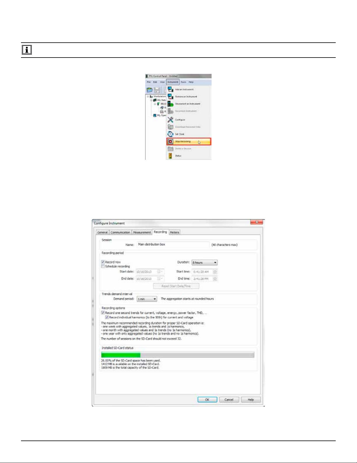
4.4.7 Configuring and Recording Data Example
The following is intended as an example of measuring and recording over a period of 8 hours.
NOTE: Set the instrument’s clock to the proper time as the clock may vary due to time zones.
1. If a recording is active, stop it by selecting Instrument > Stop Recording from the main menu.
Figure 60
2. Open the Configure Instrument dialog box (see § 4.4) and select the Recording tab.
3. Select an 8-hour recording duration by selecting the 8 hour option from the Duration drop-down list.
4. Check the Record now checkbox.
At this point the Recording tab should look similar to the figure below.
Figure 61
5. Press OK. This will write the configuration to the instrument and begin a recording (provided enough memory is
available in the instrument).
68
Power & Energy Logger Model PEL 102 and PEL 103
Page 71

4.4.8 Modifying an Instrument’s Configuration
To change or modify the instrument’s conguration, select the desired PEL listed in the PEL Network, then select the
Modify Instrument Configuration button (
), located at the top of the Status area below the Toolbar.
Figure 62
4.5 Downloading Recorded Data
Recorded measurements stored in the instrument are transferred to a database on the PC using the download command.
Assuming a recording session has been started and stopped, the instrument should have at least one recording session.
To Download a Recording:
1. Select a recorded session from Recorded session branch of the PEL Network.
Figure 63
2. To download the session, perform one of the following:
■ From the Instrument menu,
select Download Recorded Data.
or
■ From the Toolbar, click on the Download icon.
Figure 65
Figure 64
NOTE: You can also double-click on a recording to download it.
Power & Energy Logger Model PEL 102 and PEL 103
69
Page 72

This opens the Download dialog box and begins the transfer of recorded data to the computer:
Figure 66
■ You can hide the Download dialog box by selecting the Close button. This does not stop the download but
simply hides the Download dialog box so you can continue to use the PEL Control Panel.
■ The Clear All button clears the list terminating the download of any downloads in progress. It does not delete
them from the instrument or the download folder but simply removes them from the download list.
■ You can pause the download of a session by selecting it and clicking on the Pause button. To resume the
download, repeat the process. The Pause button will change to a Resume button when you select a download
that was previously paused. This indicates the action that will be taken when you select the button. The Pause
button is disabled when a recording that has finished downloading is selected.
3. Once the file has been fully downloaded, it can be opened by selecting it in the Download dialog box and click-
ing on the Open button or by double-clicking on the le. Alternatively, it can be opened from the Download Folder
dialog box (see § 4.6). The session will then be added to the My Open Sessions section:
Figure 67
4. Selecting different items under the session name in My Open Sessions will display the associated data in the data
frame on the right.
70
Power & Energy Logger Model PEL 102 and PEL 103
Page 73

4.6 Using the Download Folder
Downloaded sessions are saved to the download folder, which is located in the “…\My document\DataView\Download\
PEL\” folder. Sessions are saved so they do not need to be downloaded more than once. They are also saved so that if
you exit the PEL Control Panel while downloading, the download can resume (where it left off) the next time the program
starts.
■ To open the Download Folder dialog box select Tools > Download Folder from the main menu.
Figure 68
■ The Download Folder dialog box contains a list of instruments on the left side. This list contains instruments from
which sessions were previous downloaded. On the right is a list of sessions that are in the download folder for the
selected instrument.
■ Initially the list on the right is empty because no instrument is initially selected. Selecting an instrument on the left will
update the list on the right to display all of the sessions associated with the selected instrument that are currently in
the download folder.
■ You can use the download folder to open recordings previously downloaded even when the instrument is not
connected to the computer. To do this, select the instrument on the left that the session was downloaded from.
Next, select the desired session from the list on the right. Finally, select the Open button to open the session and
display it in the My Open Sessions navigation tree branch.
■ You can remove individually saved sessions from the download folder by selecting the desired session and clicking
on the Delete button located under the list on the right.
NOTE: A session cannot be deleted from the Download Folder dialog box if it is still currently listed in the Download dialog box. You must first open the Download dialog box (go to Instrument > Download Recorded Data) and
hit the Clear All button.
■ Note that there are two Delete buttons. The one on the left (under the list of instruments) will delete all of the saved
items for the selected instrument. The Delete button on the right (under the list of saved sessions) will delete only the
selected session from the download folder.
Each time the PEL Control Panel starts it will calculate how much space is being used on the computer’s hard drive and
compare it to the “Maximum allowable download folder size” specified at the bottom of the Download Folder dialog box.
Power & Energy Logger Model PEL 102 and PEL 103
71
Page 74

If the amount of space being used by the download folder exceeds this amount, a warning message will be displayed. No
action will be taken automatically; you are simply informed whenever the size of the download folder exceeds the amount
specified here.
4.7 PEL Reports
Several predefined report templates are available for you to use. You can choose a report template either before or after a
recording. You can also create your own custom templates.
A report is created by performing the following steps
1. Download recorded data from the instrument.
2. Open the downloaded data.
3. Select Create DataView Report from the File menu or by selecting the associated Toolbar button. The Select
Data to Export dialog box will be displayed.
4. Specify the time period of the recording that is to be used in the report and select OK. After the database is
generated, the Create Report from Template dialog box will be displayed.
5. Select the desired report template (Basic is a simplified report and Monitoring is a detailed report containing
many worksheets). Once the template is selected, select the OK button.
At the bottom of the report screen is a series of tabs used to select the desired worksheet to view.
4.7.1 Specifying the Default Report Template
The previous example required that you select the template from the Create Report from Template dialog box. You can
also specify a default template that should be used to automatically generate the report. Doing so will eliminate step 5
above.
To specify the default template, perform the following:
1. Select the Select Report option from the Tools menu. The Templates dialog box will be displayed.
2. Select the template to be used as the default.
3. Click on the Select button. An asterisk will be displayed next to the name of the default template.
You can select any of the listed templates as the default.
You can remove the selection of a default template (and be asked to select a template each time you create a report) by
clicking on the Reset button.
4.8 Power & Energy Logger (PEL) Android App
Another way to connect to a PEL instrument is through the Power & Energy Logger (PEL) Android app. This app, which can
be downloaded free from the Google Play Store (https://play.google.com/store/apps/details?id=com.aemc.pel&hl=en)
enables you to work with a PEL instrument from an Android mobile device. Android is a platform for “touch screen” mobile
devices such as tablets and smartphones. Introduced in 2007, Android has grown to become the most popular mobile
operating system in the world, with over one billion devices sold globally.
The PEL app connects to the PEL via Bluetooth. And if the PEL is connected to a LAN network, you can also communicate
with the instrument over Wi-Fi.
72
Power & Energy Logger Model PEL 102 and PEL 103
Page 75

The PEL app provides a substantial subset of the functionality provided by the PEL Control Panel. For example, you can
view data currently being measured by the instrument in real-time. This includes the type of distribution system currently
being measured, and (for AC systems) the phasor diagram appropriate for this setup. Real-time data is organized in tables
of related measurements for quick navigation and reference, and updated continuously from the instrument.
Figure 69
These data tables, which can require several pages to display, depend on the current distribution system. Different data
appears for different distribution systems; the above example shows the rst page of real-time data for a 3-phase 4-wire
system.
You can also set parameters to schedule a recording session and specify what data will be recorded. This can be a recording that starts immediately, or at a future date and time. You can also choose which data to record. Recorded data is stored
on the PEL instrument, where it can subsequently be downloaded to a PC and analyzed in detail using DataView.
In addition, you can view and/or set configuration variables on the PEL instrument. The PEL Android app enables you to
review the current configuration settings on your PEL, and change these settings as required. You can change the type of
distribution system being measured, voltage ratios, nominal frequency, current sensors options, communication-related
settings, and other information related to the instrument and its operation.
The app is provided with a complete online Help system, which can be viewed independently at http://www.pel100.us/
help-en/index.html. Consult this Help system for a complete description of the PEL app and all its capabilities.
Power & Energy Logger Model PEL 102 and PEL 103
73
Page 76

5. SPECIFICATIONS
5.1 Reference Conditions
Parameter Reference Conditions
Ambient temperature 73°F (23 °C) ± 2°F/C
Relative humidity 45% to 75% RH
Voltage No DC component in AC, no AC component in DC (< 0.1%)
Current No DC component in AC, no AC component in DC (< 0.1%)
Phase voltage 100 to 1000Vrms, without DC (< 0.5%)
Input voltage of current inputs
(except AmpFlex
Harmonics < 0.1%
Voltage unbalance 0%
Preheating Device powered for at least an hour
Common mode
Magnetic field 0 A/m AC
Electric field 0 V/m AC
®
/MiniFlex®)
50mV to 1.2V without DC (< 0.5%) for AC measurement, without AC (< 0.5%)
for DC measurement
Neutral input and enclosure are held at earth potential
Instrument powered on battery, USB disconnected
Table 13
5.2 Electrical Specifications
5.2.1 Voltage Inputs
Operating Range: up to 1000Vrms for phase-to-neutral voltages
up to 1700Vrms for phase-to-phase voltages
NOTE: Phase-to-neutral voltages lower than 2V and phase-to-phase voltages lower than 2√3 are zeroed.
Input Impedance: 1908kW (phase-to-neutral and neutral-to-earth/ground)
Max Overload: 1100Vrms
5.2.2 Current Inputs
NOTE: Current sensor inputs are “voltage” inputs (current probes have a voltage output).
Operating Range: 0.5mV to 1.2V (1V = Inom) with crest factor = √2
Input Impedance: 1MW (except for AmpFlex®/MiniFlex® current sensors)
12.4kW (AmpFlex®/MiniFlex® current sensors)
Max Overload: 1.7V
74
Power & Energy Logger Model PEL 102 and PEL 103
Page 77

5.2.3 Accuracy Specifications (excluding current sensors)
5.2.3.1 Specifications at 50/60Hz
Quantity Measurement Range Intrinsic Uncertainty
Frequency (f) 42.5 to 69Hz ± 0.1Hz
Phase to neutral voltage (V)
Phase to phase voltage (U)
Current (I) without current sensor *
Active power (P)
Reactive power (Q)
Apparent power (S)
Power factor (PF)
Tan Φ
Active energy (Ep)
PF = [0.5 inductive ; 0.8 capacitive]
Sin ϕ = [0.5 inductive ; 0.5 capacitive]
Sin ϕ = [0.5 inductive ; 0.5 capacitive]
Sin ϕ = [0.25 inductive ; 0.25 capacitive]
PF = [0.5 inductive ; 0.5 capacitive]
PF = [0.2 inductive ; 0.2 capacitive]
Tan Φ = [√3 inductive ; √3 capacitive]
Tan Φ = [3.2 inductive ; 3.2 capacitive]
PF = [0.5 inductive ; 0.8 capacitive]
10 to 100V ± 0.2% ± 0.2V **
100 to 1000V ± 0.2% ± 0.2V
17 to 170V ± 0.2% ± 0.4V **
170 to 1700V ± 0.2% ± 0.4V
0.2 to 5% Inom ± 0.2% ± 0.02% Inom **
5 to 120% Inom ± 0.2% ± 0.02% Inom
PF = 1
V = 100 to 1000V
I = 5 to 120% Inom
V = 100 to 1000V
I = 5 to 120% Inom
Sin ϕ = 1
V = 100 to 1000V
I = 5 to 120% Inom
V = 100 to 1000V
I = 5 to 120% Inom
V = 100 to 1000V
I = 5 to 120% Inom
V = 100 to 1000V
I = 5 to 120% Inom
V = 100 to 1000V
I = 5 to 120% Inom
V = 100 to 1000V
I = 5 to 120% Inom
V = 100 to 1000V
I = 5 to 120% Inom
V = 100 to 1000V
I = 5 to 120% Inom
V = 100 to 1000V
I = 5 to 120% Inom
PF = 1
V = 100 to 1000V
I = 5 to 120% Inom
V = 100 to 1000V
I = 5 to 120% Inom
± 0.5% ± 0.005% Pnom
± 0.7% ± 0.007% Pnom
± 1% ± 0.01% Qnom
± 1% ± 0.015% Qnom
± 1.5% ± 0.015% Qnom
± 3.5% ± 0.003% Qnom
± 0.5% ± 0.005% Snom
± 0.05
± 0.1
± 0.02
± 0.05
± 0.5%
± 0.6 %
Power & Energy Logger Model PEL 102 and PEL 103
75
Page 78

Quantity Measurement Range Intrinsic Uncertainty
Sin ϕ = 1
V = 100 to 1000V
I = 5 to 120% Inom
Sin ϕ = [0.5 inductive ; 0.5 capacitive]
V = 100 to 1000V
Reactive energy (Eq)
Sin ϕ = [0.5 inductive ; 0.5 capacitive]
I = 5 to 120% Inom
V = 100 to 1000V
I = 5 to 120% Inom
Sin ϕ = [0.25 inductive ; 0.25 capacitive]
V = 100 to 1000V
I = 5 to 120% Inom
Apparent energy (Es)
V = 100 to 1000V
I = 5 to 120% Inom
PF = 1
Harmonics number (1 to 25)
V = 100 to 1000V
I = 5 to 120% Inom
PF = 1
Total Harmonic Distortion (THD)
V = 100 to 1000V
I = 5 to 120% Inom
Table 14
Inom is the value of the measured current for a current sensor output of 1V. See Table 26 for the nominal current values.
Pnom and Snom are the active power and apparent power for V = 1000V, I = Inom and PF = 1.
Qnom is the reactive power for V = 1000V, I = Inom, and Sin ϕ = 1.
* The intrinsic uncertainty for input current (I) is specified for an isolated input voltage of 1V = Inom. The intrinsic uncertainty of the
connected current sensor should be added to this intrinsic uncertainty to determine the total intrinsic uncertainty. In the case of using
sensors AmpFlex® and MiniFlex®, intrinsic uncertainty is given in Table 27.
The intrinsic uncertainty for neutral current is the maximum intrinsic uncertainty on I1, I2 and I3.
** Indicative maximum value of the intrinsic uncertainty. Higher uncertainties can be noted, in particular with EMI.
± 2%
± 2%
± 2.5%
± 2.5%
± 0.5%
± 1%
± 1%
76
Power & Energy Logger Model PEL 102 and PEL 103
Page 79

5.2.3.2 Specifications @ 400Hz
Quantity Measurement Range Intrinsic Uncertainty
Frequency (F) 340 to 460Hz ± 0.1Hz
Phase to neutral voltage (V)
Phase to phase voltage (U)
Current (I) without current sensor *
Active power (P)
PF = [0.5 inductive ; 0.8 capacitive]
Active energy (Ep)
Inom is the value of the measured current for a current sensor output at 50/60Hz. See Table 26 for the nominal current values.
Pnom is the active power for V = 600V, I = Inom and PF = 1.
* The intrinsic uncertainty for input current (I) is specified for an isolated input voltage of 1V = Inom. The intrinsic uncertainty of the
connected current sensor should be added to this intrinsic uncertainty to determine the total intrinsic uncertainty. In the case of using
sensors AmpFlex
®
and MiniFlex®, intrinsic uncertainty is given in Table 27. The intrinsic uncertainty for neutral current is the maximum
intrinsic uncertainty on I1, I2 and I3.
** Indicative maximum value of the intrinsic uncertainty. Higher uncertainties can be noted, in particular with EMI.
*** For AmpFlex
®
and MiniFlex®, the maximum current is limited to 60% Inom at 50/60Hz, because of higher sensitivity.
10 to 100V ± 0.5% ± 0.5V **
100 to 600V ± 0.5% ± 0.5V
17 to 170V ± 0.5% ± 0.5V **
170 to 1700V ± 0.5% ± 0.5V
0.2 to 5% Inom ± 0.5% ± 0.05% I
nom **
5 to 120% Inom *** ± 0.5% ± 0.05% Inom
PF = 1
V = 100 to 600V
±2% ± 0.02% Pnom **
I = 5 to 120% Inom
V = 100 to 600V
±3% ± 0.03% Pnom **
I = 5 to 120% Inom
PF = 1
V = 100 to 600V
± 2% **
I = 5 to 120% Inom
Table 15
5.2.3.3 Specifications @ DC
Quantity Measurement Range Typical Intrinsic Uncertainty **
Voltage (V) V = 100 to 1000V ± 1% ± 3V
Current (I) without current sensor * I = 5% to 120% Inom ± 1% ± 0.3% Inom
Power (P)
Energy (Ep)
Inom is the value of the measured current for a current sensor output of 1 V. See Table 26 for the nominal current values.
Pnom is the power for V = 1000V and I = Inom.
* The intrinsic uncertainty for input current (I) is specified for an isolated input voltage of 1V = Inom. The intrinsic uncertainty of the
connected current sensor should be added to this intrinsic uncertainty to determine the total intrinsic uncertainty. In the case of using
sensors AmpFlex® and MiniFlex®, intrinsic uncertainty is given in Table 27.
The intrinsic uncertainty for neutral current is the maximum intrinsic uncertainty on I1, I2 and I3.
** Indicative maximum value of the intrinsic uncertainty. Higher uncertainties can be noted, in particular with EMI.
V = 100 to 1000V
I = 5% to 120% Inom
V = 100 to 1000V
I = 5% to 120% Inom
Table 16
± 1% ± 0.3% Pnom
± 1.5%
Power & Energy Logger Model PEL 102 and PEL 103
77
Page 80

5.2.3.4 Temperature
For V, U, I, P, Q, S, FP and E:
■ 300 ppm/°C, with 5% < I < 120% and PF = 1
■ 500 ppm/°C, with 10% < I < 120% and PF = 0.5 inductive
■ Typical DC offset V: 10mV/°C
I: 30 ppm x Inom/°C
5.2.3.5 Common Mode Rejection
The common mode rejection ratio on neutral input is typically 140 dB. For example, 110V applied on the neutral input will
add 11µV to AmpFlex
®
/MiniFlex® values, which is a 230mA error at 60Hz. A voltage of 110V applied on the neutral input
will add 11µV to other current sensors’ values, resulting in an additional error of 0.01% Inom.
5.2.3.6 Magnetic Field Influence
For Rogowski inputs (without sensors): 10 mA/A/m typical at 50/60 Hz.
5.2.4 Current Sensors
5.2.4.1 Precautions for Use
Refer to the safety sheet or user manual that was supplied with your current sensors for more information.
5.2.4.2 Use and Characteristics
Current clamps and exible current sensors are used to measure the current owing in a cable without opening the circuit.
They also insulate the user from dangerous voltages in the circuit.
■ The choice of current sensor to be used depends on the current to be measured and the diameter of the cables.
■ When installing current sensors, face the arrow on the probe or the sensor in the direction of the load.
78
Power & Energy Logger Model PEL 102 and PEL 103
Page 81

5.2.4.3 MiniFlex
®
MA193
The Flexible Current Sensor MiniFlex® Model MA193 can be used to measure the current in a cable without opening
the circuit. It also serves to isolate the user from hazardous voltages in the circuit. This sensor can only be used as an
accessory of an instrument. Before connecting it, if you have several sensors, you can mark each of them using one of
the color-coded ID markers supplied with the instrument to identify the phase. Then connect the sensor to the instrument.
■ Press the yellow opening device to open the Flexible coil. Then, place it around the conductor through which the
current to be measured ows (only one conductor in the sensor).
■ Close the coil. In order to optimize measurement quality, it is best to center the conductor in the coil and make
the shape of the coil as circular as possible.
■ To disconnect the coil, open it and withdraw it from the conductor. Then, disconnect the sensor from the
instrument.
MiniFlex® MA193
Nominal Range
Measurement Range
Sensor
Variation of the position of the
conductor in the sensor
Adjacent conductor carrying
alternating current
Safety
100/400/2000/10,000A
200mA to 3000A
Length = 10" (250 mm); Ø = 2.75" (70 mm)
≤ 1.5% typical, 2.5% max
≤ 1% for a conductor in contact with sensor and ≤ 2% near the snap device
EN 61010-2-032, Pollution Degree 2, 600V CAT IV, 1000V CAT III
AC
AC
Table 17
NOTE: Currents < 0.05% of the nominal range (100, 400, 2000 or 10,000A) will be displayed as zero.
The nominal ranges are reduced to 50/200/1000/5000AAC at 400Hz. MiniFlex® will operate when 10,000A is selected.
5.2.4.4 Other Current Sensors
The measurement ranges are those of the sensors. In some cases, they may differ from the ranges that can be measured
by the PEL. For use, see the manual distributed with the current sensor
NOTE: Power calculations will be zeroed when the current is zeroed.
Model MR193
Nominal Range
Measurement Range
Maximum Clamping Diameter
Variation of the position of the
conductor in the sensor
Adjacent conductor carrying
alternating current
Safety
AC, 1400ADC max
1000A
1A to 1000AAC, 10 to 1300APEAK AC+DC
One 1.6" (42mm) or two 0.98" (25.4mm) or two bus bars 1.96 x 0.19" (50 x 5mm)
< 0.5% DC to 440Hz
< 10mA/A at 50/60Hz
EN 61010-2-032, Pollution Degree 2, 300V CAT IV, 600V CAT III
Table 18
NOTE: Currents < 1AAC/DC will be displayed as zero.
Model SR193
Nominal Range
Measurement Range
Maximum Clamping Diameter
Variation of the position of the
conductor in the sensor
Adjacent conductor carrying
alternating current
Safety
AC for f ≤1 kHz
1000A
1 to 1200AAC max (I >1000A not continuously)
2" (52mm)
< 0.5% DC to 440Hz
< 10mA/A at 50/60Hz
EN 61010-2-032, Pollution Degree 2, 600V CAT IV, 1000V CAT III
NOTE: Currents < 0.5A will be displayed as zero.
Power & Energy Logger Model PEL 102 and PEL 103
Table 19
79
Page 82

AmpFlex® Sensors
Nominal Range
Measurement Range
Sensor
Variation of the position of the
conductor in the sensor
Adjacent conductor carrying
alternating current
Safety
100/400/2000/10,000A
50mA to 12000A
Length = 24" (610mm); Ø = 7.64" (190mm)
Length = 36" (910mm); Ø = 11.46" (290mm)
≤ 2% any position and ≤ 4% near snap device
≤ 1% any position and ≤ 2% near snap device
EN 61010-2-032, Pollution Degree 2, 600V CAT IV, 1000V CAT III
AC
AC
Table 20
NOTE: Currents < 0.05% for nominal range (100, 400, 2000 or 10,000A) will be displayed as zero.
The nominal ranges are reduced to 50/200/1000/5000AAC at 400Hz.
Model MN93
Nominal Range
Measurement Range
Maximum Clamping Diameter
Variation of the position of the
conductor in the sensor
Adjacent conductor carrying
alternating current
Safety
AC for f ≤1kHz
200A
0.5A to 240AAC max ( I >200A not permanent)
0.8" (20mm)
< 0.5% at 50/60Hz
≤ 15mA/A
EN 61010-2-032, Pollution Degree 2, 300V CAT IV, 600V CAT III
Table 21
NOTE: Currents < 0.1A will be displayed as zero.
Model MN193
Nominal Range
Measurement Range
Maximum Clamping Diameter
Variation of the position of the
conductor in the sensor
Adjacent conductor carrying
alternating current
Safety
5A and 100A
5A: 0.005 to 6AAC max
100A: 0.2 to 120AAC max
0.8" (20mm)
< 0.5% at 50/60Hz
≤ 15mA/A at 50/60Hz
EN 61010-2-032, Pollution Degree 2, 300V CAT IV, 600V CAT III
AC
Table 22
The 5A range of the MN193 is designed to work with secondary current transformers.
NOTE: Currents < 2.5mA x ratio on the 5A range and < 0.05A on the 100A range will be displayed as zero with this probe.
Model SL261
Nominal Range
Measurement Range
Probe Output Signal
Maximum Clamping Diameter
Variation of the position of the
conductor in the sensor
Adjacent conductor carrying
alternating current
Safety
10A and 100A
AC/DC
100mV/A: 100mA to 10A peak
10mV/A: 1 to 100A peak
1000mV peak max
0.46" (11.8mm)
< 0.5%
-33 dB typical, DC to 1 kHz
EN 61010-2-032, Pollution Degree 2, 600V CAT III
80
Table 23
Power & Energy Logger Model PEL 102 and PEL 103
Page 83

Nominal Range
Measurement Range
Maximum Clamping Diameter
Variation of the position of the
conductor in the sensor
Adjacent conductor carrying
alternating current
Safety
Model J93
3500A
AC and 5000ADC
50 to 3500AAC
50 to 5000ADC
2.83" (72 mm)
< ± 2%
> 35 dB typical, DC to 2kHz
IEC 61010-2-032, pollution degree 2, 600V CAT IV, 1000V CAT III
Table 24
®
adapter
Nominal Range
Measurement Range
Probe Output Signal
Number of transformer inputs
Safety
5A Adapter Box /Essailec
5Aac
250mA
ac to 6Aac
200mVac/Aac
3
EN 61010-2-032, Pollution degree 2, 300V CAT III
Table 25
NOTE: Currents < 2.5mA will be displayed as zero.
5.2.4.5 Accuracy
The RMS current measurement accuracy and the phase accuracy correspond to addition values (which must therefore
be added to the instrument’s accuracy), indicated as inuences on the calculations carried out by the instrument (powers,
energies, power factors, tangents, etc.).
The following specifications are considered to be in the conditions of references of the current sensor.
Current sensors with 1V output at Inom specifications
Model I nominal
Intrinsic
uncertainty
on ϕ
at 50/60 Hz
Current
(RMS or DC)
Intrinsic
uncertainty
at 50/60 Hz
1 to 50A ± 1.5% ± 1A ** - -
Typical
uncertainty
on ϕ
at 50/60 Hz
Typical
uncertainty
on ϕ
at 400 Hz
MR193
1000A
dc
100 to 800A ± 2.5%
800 to 1000A ± 4% - 0.65°
1 to 50A ± 1% ** - -
50 to 100A ± 1.5% ± 1A ± 2.5° -0.9°
SR193
1000A
ac
100 to 1200A ± 0.3% ± 0.7° + 0.2°
0.5 to 5A ± 3% ± 1A ** - - -
5 to 40A ± 2.5% ± 1A ± 5° + 2° - 1.5° @ 40A
MN93
200Aac
40 to 100A ± 2% ± 1A ± 3° + 1.2° - 0.8° @ 100A
100 to 240A ± 1% + 1A ± 2.5° ± 0.8° - 1° @ 200A
Power & Energy Logger Model PEL 102 and PEL 103
± 2°
- 0.8°
- 4.5° @ 100A
+ 0.1° @ 1000A50 to 100A ± 0.5% ± 1° + 0.25°
81
Page 84

Model I nominal
Current
(RMS or DC)
Intrinsic
uncertainty
at 50/60 Hz
Intrinsic
uncertainty
on ϕ
at 50/60 Hz
Typical
uncertainty
on ϕ
at 50/60 Hz
200mA to 5A ± 1% ± 2mA ** ± 4° - -
ac
100A
5 to 120A ± 1% ± 2.5° + 0.75° - 0.5° @100A
MN193
5 to 250mA ± 1.5% ± 0.1mA ** - - -
5A
ac
255mA to 6A ± 1% ± 5° + 1.7° - 0.5° @ 5A
5 to 40A ± 4% ± 50mA ± 1° - -
ac/dc
SL261
5A Adapter
100A
40 to 100A ± 15% ± 1° - -
ac/dc 50mA to 10A ± 3% ± 50mA ± 1.5° - -
10A
5A
ac
5 to 250mA ± 0.5% ± 2mA ** -
250mA to 6A ± 0.5% ± 1mA ± 0.5°
- -
50 to 250A ±2% + 2.5A) ±3°
250 to 500A ± (1.5% + 2.5A) ±2°
500 to 3500A ± 1% ±1.5°
3500 to 5000A
(DC only)
± 1% -
- -
J93
3500A
ac
5000Adc
Table 26
** Indicative maximum value of the intrinsic uncertainty. Higher uncertainties can be noted, in particular with EMI.
Typical
uncertainty
on ϕ
at 400 Hz
®
AmpFlex
and MiniFlex® Specifications
Sensor type I nominal
100A
400A
AmpFlex
®
A193 *
2000A
10,000A
100A
400A
®
MiniFlex
MA193 *
2000A
ac
ac
ac
ac
ac
ac
Intrinsic
uncertainty
on ϕ
at 50/60Hz
Current
(RMS or DC)
Typical intrinsic
uncertainty
at 50/60Hz
Intrinsic
uncertainty
at 400Hz
200mA to 5A ± 1.2% ± 50mA ** ± 2% ± 0.1A ** - -
5 to 120A * ± 1.2% ± 50mA ± 2% ± 0.1A ± 0.5° - 0.5°
0.8 to 20A ± 1.2% ± 0.2A ** ± 2% ± 0.4A ** - -
20 to 500A * ± 1.2% ± 0.2A ± 2% ± 0.4A ± 0.5° - 0.5°
4 to 100A ± 1.2% ± 1A ** ± 2% ± 2A ** - -
100 to 2400A * ± 1.2% ± 1A ± 2% ± 2A ± 0.5° - 0.5°
20 to 500A ± 1.2% ± 5A ** ±2% ± 10A ** - -
ac
500 to 12,000A * ± 1.2% ± 5A ± 2% ± 10A ± 0.5° - 0.5°
200mA to 5A ± 1.2% ± 50mA ** ± 2% ± 0.1A ** - -
5 to 120A * ± 1.2% ± 50mA ± 2% ± 0.1A ± 0.5° - 0.5°
0.8 to 20A ± 1.2% ± 0.2A ** ± 2% ± 0.4A ** - -
20 to 500A * ± 1.2% ± 0.2A ± 2% ± 0.4A ± 0.5° - 0.5°
4 to 100A ± 1.2% ± 1A ** ± 2% ± 2A ** - -
100 to 2400A * ± 1.2% ± 1A ± 2% ± 2A ± 0.5° - 0.5°
Typical
uncertainty
on ϕ
at 400Hz
ac
3000A
500 to 3000A * ± 1.2% ± 5A ± 2% ± 10A ± 0.5° - 0.5°
Table 27
20 to 500A ± 1.2% ± 5A ** ±2% ± 10A ** - -
* The nominal ranges are reduced to 50/200/1000/5000A
ac at 400Hz.
** Indicative maximum value of the intrinsic uncertainty. Higher uncertainties can be noted, in particular with EMI.
82
Power & Energy Logger Model PEL 102 and PEL 103
Page 85

When no current sensor is connected, the current values are forced to zero.
Distribution system Abbreviation l
Split phase (1-phase 2-wire)
Split phase (1-phase 3-wire)
3-phase 3-wire ∆
3-phase 3-wire Open ∆
3-phase 3-wire Y 2
3-phase 3-wire ∆
3-phase 3-wire Open ∆
3-phase 3-wire Y
3-phase 3-wire ∆ balanced
3-phase 4-wire Y
3-phase 4-wire Y balanced
3-phase 4-wire Y 2½
3-phase 4-wire ∆
3-phase 4-wire Open ∆
DC 2-wire
DC 3-wire
DC 4-wire
5.3 Bluetooth
Bluetooth 2.1
■ Class 1 (range: 100 m)
■ Nominal output power: +15 dBm
1
1P-2W
1P-3W
3P-3W∆2 • − •
3P-3W02 • − •
3P-3WY2 • − •
3P-3W∆3 • • •
3P-3W03 • • •
3P-3WY • • •
3P-3W∆B − − •
3P-4WY • • •
3P-4WYB • − −
3P-4WY2 • • •
3P-4W∆ • • •
3P-4WO∆ • • •
DC-2W • − −
DC-3W • • −
DC-4W • • •
n
Nominal sensitivity: -82 dBm
n
Rate : 115.2 kbits/s
• − −
• • −
l
2
l
3
5.4 Power Supply
AC Power (external power supply) - Overvoltage CAT II
■ Operating Range: 110V/230V (± 10%) @ 50/60Hz
■ Max Power: 15VA (rated to 30 VA max)
Battery Power
■ Type: Rechargeable NiMH battery
■ Charge Time: 5 hours approx
■ Recharging Temperature: 50° to 104°F (10° to 40°C)
NOTE: Configuration data is saved for up to 5 years during a low battery condition.
When the instrument is off, the real-time clock is maintained for two weeks or longer.
Autonomy
■ 30 minutes minimum
■ 60 minutes typical
Power & Energy Logger Model PEL 102 and PEL 103
83
Page 86

5.5 Mechanical Specifications
4009819
Dimensions: 10.08 x 4.92 x 1.46" (256 x 125 x 37mm)
Weight: < 1 kg
Drop Test: 1 m in the most severe position without permanent mechanical damage and functional deterioration
Degrees of Protection: Provided by enclosure (IP code) according to IEC 60529
IP 54 instrument not connected (de-energized) / not including the terminals
IP20 instrument connected (operating)
5.6 Environmental Specifications
Reference Temperature: 20 to 26°C (68 to 78.8°F) from 45 to 75% RH
Operating Temperature: 0 to 42.5°C (32 to 108.5°F) from 10 to 85% RH
0 to 50°C (32 to 122°F) from 45 to 75% RH
Storage Temperature:
With batteries: -20 to 35°C (-4 to 95°F) from 0 to 95% RH
-20 to 50°C (-4 to 122°F) from 0 to 75% RH
Without batteries: -20 to 70°C (-4 to 158°F) from 0 to 75% RH
Recharging Temperature: n/a
Altitude: Operating: 0 to 2000 m (6560 ft); Non-Operating: 0 to 10000m (32800 ft)
5.7 Safety Specifications
Electrical Safety
The instrument complies with IEC 61010-1, and IEC 61010-2-030 for the following:
■ Measurement inputs and enclosure: 600V CAT IV / 1000V CAT III, pollution degree 2
■ Power supply: 300V overvoltage category II, pollution degree 2
Conforms to UL Std. UL 61010-1
Conforms to UL Std. UL 61010-2-030
Cert. to CAN/CSA Std. C22.2 No. 61010-1
Cert. to CSA Std. C22.2#61010-2-030
For current sensors, see § 5.2.4.4
The current sensors comply with IEC 61010-2-032
The test leads and alligator clips comply with IEC 61010-031
5.8 Electromagnetic Compatibility
■ Emissions and immunity in an industrial setting compliant with IEC 61326-1
(with an inuence of 0.5% typical of the full scale
Specifications are subject to change without notice.
84
Power & Energy Logger Model PEL 102 and PEL 103
Page 87

6. MAINTENANCE
6.1 Battery
Your instrument is equipped with a NiMH battery. This technology offers several advantages:
■ Long battery charge life for a limited volume and weight.
■ Possibility of quickly recharging your battery.
■ Significantly reduced memory effect: you can recharge your battery even if it is not fully discharged.
■ Respect for the environment: no pollutant materials such as lead or cadmium, in compliance with the applicable
regulations.
After prolonged storage, the battery may be completely discharged. If so, it must be completely recharged.
Your instrument may not function during part of this recharging operation.
Full recharging of a completely discharged battery may take several hours.
In this case, at least 5 charge/discharge cycles will be necessary for your battery to recover 95% of its capacity.
To make the best possible use of your battery and extend its effective service life:
■ Only charge your instrument at temperatures between 50°F and 104°F (10°C and 40°C).
■ Comply with the conditions of use defined in the operating manual.
■ Comply with the storage conditions specified in the operating manual.
Before first use, charge and discharge the instrument one or two cycles to ensure the proper level display of the
battery indicator.
Note that if you are unsure about changing the battery, we recommend having this done at our Service Center as
part of the PEL instrument’s regular maintenance.
6.2 Battery Indicator
The Yellow/Red LED (see #6 Figure 8) is used to indicate the status of the battery.
When the power is on, the battery is charging until it is full.
■ LED OFF: Battery full (with or without power supply).
■ Yellow LED ON/No blinks: Battery is charging.
■ Yellow LED blinks twice per second: Battery is recovering after a full discharge.
■ Red LED blinks twice per second: Low battery (and no power supply).
6.3 Cleaning
Disconnect the instrument from any source of electricity.
■ Use a soft cloth, dampened with soapy water. Rinse with a damp cloth and dry rapidly with a dry cloth.
■ Do not use the instrument if the terminals or keyboard are wet. Dry them first.
■ Do not use alcohol, solvents, or hydrocarbons.
■ Do not splash water directly on the instrument.
Power & Energy Logger Model PEL 102 and PEL 103
85
Page 88

6.4 Updating the Internal Software
With a dedication to the best possible service in terms of performance and technical upgrades, AEMC provides you with
updates to the firmware of the device available free of charge on our web site:
www.aemc.com
To download updates, go to the Software / Firmware download page.
Connect the device to your PC using the USB cord provided.
Follow the instructions of the update utility.
Note: updating the embedded software could reset the configuration and causes the loss of the stored data. As a
precaution, save the stored data to a PC before updating the embedded software.
86
Power & Energy Logger Model PEL 102 and PEL 103
Page 89

APPENDIX A
A.1 Measurements
A.1.1 Definition
Calculations are done according to IEC 61557-12 and IEC 61010-4-30.
Geometric representation of active and reactive power:
Q
Source Load
Import active powerExport active power
12
Import
reactive
power
Export
reactive
power
IND
Source
INDCAP
Q
CAP
43
Load
S
φ
P
P
Figure 70
Diagram in accordance with clauses 12 and 14 of IEC 60375.
Reference of this diagram is the current vector (xed on right-hand line).
The voltage vector V varies its direction according to the phase angle ϕ.
The phase angle ϕ between voltage V and current I is taken to be positive in the mathematical sense (counter-clockwise).
A.1.2 Sampling
A.1.2.1 Sampling Period
Depends on main frequency: 50Hz, 60Hz or 400Hz
Sampling period is calculated every second
■ Main frequency f = 50Hz
- Inside 42.5 to 57.5Hz (50Hz ±15%), sampling period is locked to main frequency.
128 samples are available for each main cycle.
- Outside 42.5 to 57.5Hz, sampling period is 128*50Hz.
■ Main frequency f = 60Hz
- Inside 51 to 69Hz (60Hz ±15%), sampling period is locked to main frequency.
128 samples are available for each main cycle.
- Outside 51 to 69Hz, sampling period is 128*60Hz.
Power & Energy Logger Model PEL 102 and PEL 103
87
Page 90

■ Main frequency f = 400Hz
- Inside 340 to 460Hz (400Hz ±15%), sampling period is locked to main frequency.
16 samples are available for each main cycle.
- Outside 340 to 460Hz, sampling period is 16*400Hz.
DC is not a frequency parameter for sampling. A pure DC measured signal is considered to be outside the frequency
ranges. Then, the sampling frequency is, according to the preselected main frequency, 6.4kHz (50/400Hz) or 7.68kHz
(60Hz).
A.1.2.2 Locking of Sampling Frequency
■ By default, sampling frequency is locked on V1
■ If V1 is missing, sampling frequency tries to lock to V2, then V3, I1, I2 and I3
A.1.2.3 AC/DC
The PEL performs AC and DC measurements for alternative current and/or direct current distribution systems. Selection
of AC or DC is done by the user.
AC +DC values are not available with PEL.
NOTE: AC+DC values could be calculated after download using the DataView® software.
A.1.2.4 Measurement of Neutral Current
For the PEL 102 and PEL 103, according to the distribution system, neutral current is calculated.
A.1.2.5 “1 second” Quantities
The instrument calculates the following quantities every second, according to § A.2.
“1 second” quantities are used for:
■ Real time values
■ “1 second” trends
■ Aggregation of values for “aggregated” trends (see § A.1.2.6)
■ Min and max determination for “aggregated” trends
All “1 second” quantities are saved on the SD-Card, during the recording time.
A.1.2.6 Aggregation
An aggregated quantity is a value calculated for a dened period, according to the formulas specied in Table 29.
Aggregation periods always start on rounded hours/minutes. Aggregation period is the same for all quantities. The period
is one of the following: 1, 2, 3, 4, 5, 6, 10, 12, 15, 20, 30 and 60mn.
All aggregated quantities are saved on the SD-Card, during the recording session. They can be displayed in the PEL Control Panel (see § 4.3).
A.1.2.7 Max
Max represents the maximum values of the “1 second” quantities for the considered aggregation period. They are saved
with the date and time of the Max (see Table 28 for the available values).
88
Power & Energy Logger Model PEL 102 and PEL 103
Page 91

A.1.2.8 Energy Calculations
Energies are calculated every second.
The “Total” energy is the demand during the recording session.
The “Partial” energy can be determined during an integration period with the following values: 1 h, 1 day, 1 week, 1 month.
The partial energy index is available only in real-time. It is not recorded.
However, the “Total” energy is available with the recording session data.
A.2 Measurement Formulas
PEL measures 128 samples per cycle (except 400 Hz with 16 samples) and calculates the voltage, current and active
power quantities on a cycle.
PEL instruments measure or calculate the following quantities on a cycle (128 samples per cycle, except 400Hz with 16
samples). Then the PEL calculates an aggregated value for 10 cycles (50Hz), 12 cycles (60Hz) or 80 cycles (400Hz).
The 10/12 cycles quantities (50Hz) are aggregated for 50/60 cycles (“1 second” quantities).
Quantities Formula Comments
AC RMS Line-to-neutral
voltage (V
)
L
vL = v1, v2 or v3 elementary sample
N = Number of samples
DC voltage (V
)
L
AC RMS Line-to-line
voltage (U
AC RMS Current (I
DC Current (I
)
L
)
L
)
L
Voltage crest factor (V-CF)
Current crest factor (I-CF)
Unbalance (u
(real-time only)
)
2
Active Power (PL)
Reactive Power (Q
)
L
with
L = v1, v2 or v3 elementary sample
N = Number of samples
ab = u12, u23 or u
N = Number of samples
elementary sample
31
iL = i1, i2 or i3 elementary sample
N = Number of samples
iL = i1, i2 or i3 elementary sample
N = Number of samples
CF
is the ratio of average crest values and rms
VL
CF
is the ratio of average crest values and rms
IL
value of 10/12 periods
value of 10/12 periods
L = I1, I2 or I3 elementary sample
N = Number of samples PT[1s]= P1[1s] + P2[1s]
+ P3[1s]
Reactive power includes harmonics.
"sign[1s]" is the reactive power sign
Total reactive power calculation QT [1s] is vector.
Apparent Power (S
)
L
Power Factor (PFL)
Power & Energy Logger Model PEL 102 and PEL 103
Total apparent power ST [1s] is an arithmetic
value
89
Page 92

Quantities Formula Comments
−
=
1
0
N
x
Cos φ [10/12] is the cosinus of the dierence
between the phase of the fundamental of the
Cos φ
L
current I and the phase of the fundamental of
the line-to-neutral voltage V for 10/12 cycles
values
TAN Φ
Line-to-neutral voltage
harmonic distortion rate
THD_VL (%)
Line-to-line voltage
harmonic distortion rate
THD_Uab (%)
Current harmonic
distortion rate
THD_IL (%)
Q[10/12] and P[10/12] are the 10/12 periods
value for Q and P.
THD is calculated as % of fundamental
VH1 is the value of fundamental
THD is calculated as % of fundamental
UH1 is the value of fundamental
THD is calculated as % of fundamental
IH1 is the value of fundamental
Table 28
A.3 Aggregation
Aggregated quantities are calculated for a dened period according to the following formulas based on 50/60 cycles.
Aggregation can be averaging or quadratic averaging, or other methods.
Quantities Formula
1
N
Line-to-neutral voltage (V
(RMS)
)
L
aggV
−
1
2
][
N
]1[
sV
×=
LL
x
∑
0
x
=
Line-to-neutral voltage (V
(DC)
Line-to-line voltage
(U
)
ab
(RMS)
Current (I
(RMS)
)
L
Current (IL)
(DC)
Voltage crest factor
(CFVL)
Current crest factor
(CFIL)
Frequency (F)
Active Power
on source (P
)
L
Active Power
on load (P
)
L
Reactive Power
on source (Q
)
L
−
1
)
L
V
L
U
N
1
×=
]agg[
∑
N
=
0
x
−
N
1
×=
]agg[
∑
N
=
x
]200[
msV
Lx
1
2
]1[
sU
abxab
0
ab = 12, 23 or 31
−
1
][
aggI
]agg[
I
L
aggF
aggP
aggP
aggQ
N
1
2
×=
∑
N
x
−
1
N
1
×=
∑
N
=
0
x
N
1
×=
aggCF
][
∑
N
1
N
1
×=
aggCF
][
∑
N
1
N
1
×=
][
∑
N
x
1
×=
][
∑
N
1
×=
][
N
N
1
×=
][
∑
N
x
=
N
∑
x
=
]1[
sI
LxL
=
0
]200[
msI
Lx
sCF
]1[
VLVL
sCF
]1[
ILIL
−
1
]1[
sF
x
0
]1[
sP
SLxSL
−
1
=
0
−
1
SLxSL
0
]1[
sP
SLxSL
]1[
sQ
90
Power & Energy Logger Model PEL 102 and PEL 103
Page 93

Quantities Formula
Reactive Power
on load (Q
Apparent Power (S
)
L
)
L
Power Factor on source (PFL)
with associated quadrant
Active Power
on load (P
)
L
Reactive Power
on source (Q
)
L
Reactive Power
on load (Q
Apparent Power (S
)
L
)
L
Power Factor on source (PFL)
with associated quadrant
Power Factor on load (PF
with associated quadrant
Cos ϕ
on source
L
with associated quadrant
)
LL
Cos ϕL on load
with associated quadrant
Tan ΦS on source
Tan ΦL on load
Line-to-neutral voltage harmonic
distortion rate THD_VL (%)
Line-to-line voltage harmonic
distortion rate THD_Uab (%)
Current harmonic distortion rate
(%)
THD_I
L
−
1
aggQ
aggS
aggPF
aggP
aggQ
aggQ
aggS
aggPF
aggPF
][)Cos(
agg
agg
][)Tan(
agg
][)Tan(
agg
1
][_
aggVTHD
N
][_
aggUTHD
][_
aggITHD
N
1
×=
][
∑
N
=
x
−
N
1
×=
][
∑
N
=
x
−
1
N
1
×=
][
∑
N
=
0
x
−
N
1
×=
][
∑
N
=
x
−
1
N
1
×=
][
∑
N
=
0
x
N
1
×=
][
∑
N
=
x
−
N
1
×=
][
∑
N
=
x
−
1
N
1
×=
][
∑
N
=
0
x
−
1
N
1
×=
][
∑
N
=
0
x
−
1
N
1
×=
∑
N
=
0
x
−
N
1
×=
][)Cos(
∑
N
=
x
−
1
N
1
×=
∑
N
=
0
x
−
1
N
1
×=
∑
N
=
0
x
−
1
N
×=
∑
=
0
x
−
1
N
1
×=
∑
N
=
0
x
−
N
1
×=
∑
N
=
x
]1[
sQ
RLxRL
0
1
0
]1[
sS
LxL
]1[
sPF
SLxSL
1
]1[
sP
SLxSL
0
]1[
sQ
SLxSL
−
1
]1[
sQ
RLxRL
0
1
0
]1[
sS
LxL
]1[
sPF
SLxSL
]1[
sPF
RLxRL
]1[)Cos(
s
ϕϕ
SxS
LL
1
0
ϕϕ
ϕϕ
LxL
]1[)Cos(
s
ϕϕ
RLRL
x
]1[)Tan(
s
SxS
]1[)Tan(
s
RR
x
]1[_
sVTHD
]1[_
sUTHD
abxab
1
0
]1[_
sITHD
LxL
Table 29
NOTE: N is the number of “1 second” values for the considered aggregation period (1, 2, 3, 4, 5, 6, 10, 12, 15, 20, 30 or 60 min).
Power & Energy Logger Model PEL 102 and PEL 103
91
Page 94

A.4 Supported Electrical Networks
The following types of distribution systems are supported:
■ V1, V2, V3 are the line-to-neutral voltages of the installation under test
■ [V1=VL1-N; V2=VL2-N; V3=VL3-N].
■ Low caps v1, v2, v3 are used for time values
■ U12, U23, U31 are the line-to-line voltages of the installation under test.
■ Low caps are used for time values [u12 = v1-v2; u23= v2-v3, u31=v3-v1]
■ I1, I2, I3 are the currents owing in the line conductors of the installation under test.
■ Low caps i1, i2, i3 are used for time values
Distribution
System
Single phase
(1-Phase 2-Wire)
Split phase
(1-Phase 3-Wire)
3-Phase 3-Wire ∆
[2 current sensors]
3-Phase 3-Wire
Open-∆
[2 current sensors]
3-Phase 3-Wire Y
[2 current sensors]
3-Phase 3-Wire ∆ 3P-3W∆3
3-Phase 3-Wire
Open-∆
3-Phase 3-Wire Y 3P-3WY3 see § 3.6.3.6
Abbreviation Comments
1P-2W
1P -3W
3P-3W∆2
3P-3WO2 see § 3.6.3.3
3P-3WY2 see § 3.6.3.5
3P-3WO3 see § 3.6.3.4
Voltage measurements are performed between L1 and N.
Current measurements are performed on L1 conductor.
Voltage measurements are performed between L1, L2 and N.
Current measurements are performed on L1 and L2
conductors.
Neutral current is calculated: iN = i1 + i2
Power measurement method is based on 3 wattmeters method with
virtual neutral.
Voltage measurements are performed between L1, L2 and L3.
Current measurements are performed on L1 and L3 conductors.
I2 current is calculated (no current sensor connected on L2):
i2 = - i1 - i3
Neutral is not available for current and voltage measurement
Power measurement method is based on 3 wattmeters method with
virtual neutral.
Voltage measurements are performed between L1, L2 and L3.
Current measurements are performed on L1, L2 and L3 conductors.
Neutral is not available for current and voltage measurement
Reference
Diagram
see § 3.6.1
see § 3.6.2
see § 3.6.3.1
see § 3.6.3.2
3-Phase 3-Wire ∆
balanced
3-Phase 4-Wire Y 3P-4WY
3-Phase 4-Wire Y
balanced
92
3P-3W∆B
3P-4WYB
Power measurement is based on 1 wattmeter method.
Voltage measurements are performed between L1 and L2.
Current measurements are performed on L3 conductor.
U23 = U31 = U12.
I1 = I2 = I3
Power measurement method is based on 3 wattmeters method with
neutral.
Voltage measurements are performed between L1, L2 and L3.
Current measurements are performed on L1, L2 and L3 conductors.
Neutral current is calculated: iN = i1 + i2 + i3.
Power measurement is based on single phase wattmeter method.
Voltage measurements are performed between L1 and N.
Current measurements are performed on L1 conductor.
V1 = V2 = V3
U23 = U31 = U12= V1 x √3.
I1 = I2 = I3
Power & Energy Logger Model PEL 102 and PEL 103
see § 3.6.3.7
see § 3.6.4.1
see § 3.6.4.2
Page 95

3-Phase 4-Wire Y 2½ 3P-4WY2
3-Phase 4-Wire ∆ 3P-4W∆
3-Phase 4-Wire
Open-∆
DC 2-Wire DC-2W
DC 3-Wire DC-3W
DC 4-Wire DC-4W
3P-4WO∆ see § 3.6.5.2
This method is named 2½ element method.
Power measurement method is based on 3 wattmeters method with
virtual neutral.
Voltage measurements are performed between L1, L3 and N.
V2 is calculated: v2 = - v1 - v3, u12 = 2·v1 + v3, u23= - v1 - 2·v3. It
supposes that V2 is balanced.
Current measurements are performed on L1, L2 and L3 conductors.
Neutral current is calculated: iN = i1 + i2+i3
Power measurement method is based on 3 wattmeters method with
neutral, but no power information for each phase is available.
Voltage measurements are performed between L1, L2 and L3.
Current measurements are performed on L1, L2 and L3 conductors.
Neutral current is calculated only for a transformer branch:
iN = i1 + i2
Voltage measurements are performed between L1 and N.
Current measurements are performed on L1 conductor.
Voltage measurements are performed between L1, L2 and N.
Current measurements are performed on L1 and L2 conductors.
Negative (return) current is calculated : iN = i1 + i2
Voltage measurements are performed between L1, L2, L3 and N.
Current measurements are performed on L1, L2 and L3 conductors.
Negative (return) current is calculated : iN = i1 + i2 + i3
see § 3.6.4.3
see § 3.6.5.1
see § 3.6.6.1
see § 3.6.6.2
see § 3.6.6.3
Table 30
Power & Energy Logger Model PEL 102 and PEL 103
93
Page 96

A.5 Phase Order
Every second, the PEL determines the phase order. If the phase order is incorrect, the red Phase Order indicator on the
PEL front panel blinks (see § 2.11). In addition, on the PEL 103, the Phase Order Incorrect icon appears on the LCD
Display screen.
Setting the correct phase order for a distribution system requires that the current phase order, voltage phase order, and
current vs voltage phase order for that distribution system are all correct. Note that:
■ Phase order for voltage channels only is displayed when voltages are displayed on the LCD screen. The voltage
phase order is derived from the FFT analysis.
■ Phase order for current channels only is displayed when currents are displayed.
■ Phase order for voltage and current channels is displayed when the other screens are displayed.
■ Load or Source is set by the DataView PEL Control Panel.
In some distribution systems (such as DC) the phase order does not apply in every instance.
The following three tables show information for each distribution system for setting the correct current phase order, voltage
phase order, and current vs voltage phase order respectively.
A.5.1 Current Phase Order
Distribution
System
Single phase
(1-Phase 2-Wire)
Split phase
(1-Phase 3-Wire)
3-Phase 3-Wire ∆
[2 current sensors]
3-Phase 3-Wire Open-∆
[2 current sensors]
3-Phase 3-Wire Y
[2 current sensors]
3-Phase 3-Wire ∆ 3P-3W∆3
3-Phase 3-Wire Open-∆ 3P-3WO3
3-Phase 3-Wire Y 3P-3WY3
3-Phase 3-Wire ∆
balanced
3-Phase 4-Wire Y 3P-4WY Yes [ϕ (I1, I3), ϕ (I3, I2), ϕ (I2, I1)] = 120° ± 30°
3-Phase 4-Wire Y
balanced
3-Phase 4-Wire Y 2½ 3P-4WY2 Yes [ϕ (I1, I3), ϕ (I3, I2), ϕ (I2, I1)] = 120° ± 30°
Abbreviation
1P-2W No
1P -3W Yes ϕ (I2, I1) = 180° ± 30°
3P-3W∆2
3P-3WO2
3P-3WY2
3P-3W∆B No
3P-4WYB No
Current Phase
Order
Yes
Yes [ϕ (I1, I3), ϕ (I3, I2), ϕ (I2, I1)] = 120° ± 30°
ϕ (I1, I3) = 120° ± 30°
No I2 current sensors
Comments
94
Power & Energy Logger Model PEL 102 and PEL 103
Page 97

3-Phase 4-Wire ∆ 3P-4W∆
3-Phase 4-Wire Open-∆ 3P-4WO∆
DC 2-Wire DC-2W No
DC 3-Wire DC-3W No
DC 4-Wire DC-4W No
A.5.2 Voltage Phase Order
Yes [ϕ (I1, I3), ϕ (I3, I2), ϕ (I2, I1)] = 120° ± 30°
Distribution
System
Single phase
(1-Phase 2-Wire)
Split phase
(1-Phase 3-Wire)
3-Phase 3-Wire ∆
[2 current sensors]
3-Phase 3-Wire Open-∆
[2 current sensors]
3-Phase 3-Wire Y
[2 current sensors]
3-Phase 3-Wire ∆ 3P-3W∆3
3-Phase 3-Wire Open-∆ 3P-3WO3
3-Phase 3-Wire Y 3P-3WY3
3-Phase 3-Wire ∆
balanced
3-Phase 4-Wire Y 3P-4WY Yes (on V) [ϕ (V1, V3), ϕ (V3, V2), ϕ (V2, V1)] = 120° ± 10°
3-Phase 4-Wire Y
balanced
3-Phase 4-Wire Y 2½ 3P-4WY2 Yes (on V)
Abbreviation
1P-2W No
1P -3W Yes ϕ (V2, V1) = 180° ± 10°
3P-3W∆2
3P-3WO2
3P-3WY2
3P-3W∆B No
3P-4WYB No
Voltage Phase
Order
Yes (on U)
Comments
[ϕ (U12, U31), ϕ (U31, U23), ϕ (U23, U12)] = 120° ± 10°
ϕ (V1, V3) = 120° ± 10°
No V2
3-Phase 4-Wire ∆ 3P-4W∆
Yes (on U)
3-Phase 4-Wire Open-∆ 3P-4WO∆
DC 2-Wire DC-2W No
DC 3-Wire DC-3W No
DC 4-Wire DC-4W No
Power & Energy Logger Model PEL 102 and PEL 103
ϕ (V1, V3) = 180° ± 10°
[ϕ (U12, U31), ϕ (U31, U23), ϕ (U23, U12)] = 120° ± 10°
95
Page 98

A.5.3 Current vs Voltage Phase Order
Distribution
System
Single phase
(1-Phase 2-Wire)
Split phase
(1-Phase 3-Wire)
3-Phase 3-Wire ∆
[2 current sensors]
3-Phase 3-Wire Open-∆
[2 current sensors]
3-Phase 3-Wire Y
[2 current sensors]
3-Phase 3-Wire ∆ 3P-3W∆3
3-Phase 3-Wire Open-∆ 3P-3WO3
3-Phase 3-Wire Y 3P-3WY3
3-Phase 3-Wire ∆
balanced
3-Phase 4-Wire Y 3P-4WY Yes
3-Phase 4-Wire Y
balanced
3-Phase 4-Wire Y 2½ 3P-4WY2 Yes
Abbreviation
1P-2W Ye s
1P -3W Yes
3P-3W∆2
3P-3WO2
3P-3WY2
3P-3W∆B Ye s
3P-4WYB Ye s
Current
vs Voltage
Phase Order
Yes
Yes
Comments
(I1, V1) = 0° ± 60° for load
ϕ
ϕ (I1, V1) = 180° ± 60° for source
[ϕ (I1, V1), ϕ (I2, V2)] = 0° ± 60° for load
[ϕ (I1, V1), ϕ (I2, V2)] = 180° ± 60° for source
[ϕ (I1, U12), ϕ (I3, U31)] = 30° ± 60° for load
[ϕ (I1, U12), ϕ (I3, U31)] = 210° ± 60° for source
No I2 current sensor
[ϕ (I1, U12), ϕ (I2, U23), ϕ (I3, U31)] = 30° ± 60° for load
[ϕ (I1, U12), ϕ (I2, U23), ϕ (I3, U31)] = 210° ± 60° for source
ϕ
(I3, U12) = 90° ± 60° for load
ϕ (I3, U12) = 270° ± 60° for source
[ϕ (I1, V1), ϕ (I2, V2), ϕ (I3, V3)] = 0° ± 60° for load
[ϕ (I1, V1), ϕ (I2, V2), ϕ (I3, V3)] = 180° ± 60° for source
(I1, V1) = 0° ± 60° for load
ϕ
ϕ (I1, V1) = 180° ± 60° for source
[ϕ (I1, V1), ϕ (I3, V3)] = 0° ± 60° for load
[ϕ (I1, V1), ϕ (I3, V3)] = 180° ± 60° for source
No V2
3-Phase 4-Wire ∆ 3P-4W∆
3-Phase 4-Wire Open-∆ 3P-4WO∆
DC 2-Wire DC-2W No
DC 3-Wire DC-3W No
DC 4-Wire DC-4W No
96
Yes
[ϕ (I1, U12), ϕ (I2, U23), ϕ (I3, U31)] = 30° ± 60° for load
[ϕ (I1, U12), ϕ (I2, U23), ϕ (I3, U31)] = 210° ± 60° for source
Power & Energy Logger Model PEL 102 and PEL 103
Page 99

A.6 Quantities According to the Supply Systems
= YES
Quantities
V
1
V
2
V
3
V
1
V
2
V
3
U
12
U
23
U
31
I
1
I
2
I
3
I
N
I
1
I
2
I
3
I
N
V1
CF
V2
CF
V3
CF
I1
CF
I2
CF
I3
CF
u
2
F
P
1
P
2
P
3
P
T
P
1
P
2
P
3
P
T
P
1
P
2
P
3
P
T
Q
1
Q
2
Q
3
Q
T
RMS
RMS
RMS
DC
DC
DC
RMS
RMS
RMS
RMS
RMS
RMS
RMS
DC
DC
DC
DC
Source
Source
Source
Source
Load
Load
Load
Load
1P-2W 1P-3W
3P-3W∆2
3P-3WO2
3P-3WY2
3P-3W∆3
3P-3WO3
3P-3WY3
3P-3W∆B 3P-4WY 3P-4WYB 3P-4WY2
3P-4W∆
3P-4WO∆
DC-2W DC-3W DC-4W
(1) (1)
(1)
(1) (1)
(1) (1) (1)
(1) (1)
(2) (1) (1)
(1) (1)
(5) (5) (1) (5) (5)
(5) (5)
(1)
(1)
(2) (1) (1)
(1)
(4) (4) (4) (3)
(1) (1) (3)
(1)
(1)
(1) (1) (3)
(1)
(1)
(1) (1) (3)
(1)
(1)
(1) (1) (3)
(1)
(1)
Power & Energy Logger Model PEL 102 and PEL 103
97
Page 100

Quantities
Q
Q
Q
Q
Q
Q
Q
Q
S
S
S
S
PF
PF
PF
PF
PF
PF
PF
PF
PF
PF
PF
PF
Cos ϕ
Cos ϕ
Cos ϕ
Cos ϕ
Source
1
Source
2
Source
3
Source
T
Load
1
Load
2
Load
3
Load
T
1
2
3
T
1
2
3
T
Source
1
Source
2
Source
3
Source
T
Load
1
Load
2
Load
3
Load
T
1
2
3
T
Cos ϕ1Source
Cos ϕ2Source
Cos ϕ3Source
Cos ϕMSource
Cos ϕ
Cos ϕ
Cos ϕ
Cos ϕ
Load
1
Load
2
Load
3
Load
T
TAN Φ
TAN Φ Source
TAN Φ Load
Hi_V
1
Hi_V
Hi_V
i=1
2
to 50(6)
3
1P-2W 1P-3W
3P-3W∆2
3P-3WO2
3P-3WY2
3P-3W∆3
3P-3WO3
3P-3WY3
3P-3W∆B 3P-4WY 3P-4WYB 3P-4WY2
3P-4WO∆
(1) (1) (3)
(1)
(1)
(1) (1) (3)
(1)
(1)
(1) (1) (3)
(1)
(1)
(1) (1) (3)
(1)
(1)
(1) (1) (3)
(1)
(1)
(1) (1) (3)
(1)
(1)
(1) (1) (3)
(1)
(1)
(1) (1) (3)
(1)
(1)
(1) (1) (3)
(1)
(3) (1)
(3) (1) (3)
(3)
(3)
(1) (3)
(1)
3P-4W∆
DC-2W DC-3W DC-4W
98
Power & Energy Logger Model PEL 102 and PEL 103
 Loading...