

Page 1

User Manual
ScopiX IV
OX 9062
OX 9102
OX 9104
OX 9304
DIGITAL OSCILLOSCOPES
- 60MHz, 2 isolat
- 100MHz, 2 isolated channels
- 100MHz, 4 isolated channels
- 300MHz, 4 isolated channels
ed channels
Page 2
2
Thank you for purchasing a ScopiX IV digital oscilloscope with isolated channels.
and reuse.
For best results from your instrument:
Read this user manual carefully
Observe the precautions for use
WARNING, risk of DANGER! Refer to these
instructions whenever this danger symbol appears.
Indoor use.
Instrument entirely protected by double insulation. Earth terminal.
Chauvin Arnoux has adopted an Eco-Design
approach in designing this instrument. Analysis of
the complete lifecycle has enabled us to control and
optimize the effects of the product on the
environment. In particular this instrument exceeds
regulation requirements with respect to recycling
The product is declared recyclable following an
analysis of the life cycle in accordance with
standard ISO 14040.
The CE marking indicates conformity with
European directives, in particular LVD and EMC.
Definition of measurement categories:
Measurement category IV corresponds to measurements taken at the source of low-voltage installations.
Example: power feeders, counters and protection devices.
In the European Union, this product is subject to
selective collection and recycling at end-of-life as
waste electric and electronic equipment under
directive 2002/96/EC (WEEE): this equipment
must not be treated as an ordinary household
waste. Spent batteries must not be treated as
ordinary household waste. Take them to the
appropriate collection point for recycling.
Risk of electric shocks: instructions for connecting
and disconnecting the inputs. Always connect the
probes or adapters to the instrument before
connecting them to the measurement points.
Always disconnect the probes or leads from the
measurement points before disconnecting them
from the instrument. These instructions apply
before cleaning the instrument and before
opening the cover on the battery compartment
and the probe calibration outputs.
Application or withdrawal not authorized on
conductors carrying dangerous voltages. Type B
current sensor as per EN 61010-2-032.
Measurement category III corresponds to measurements on building installations.
Example: distribution panel, circuit-breakers, machines or fixed industrial devices.
Measurement category II corresponds to measurements taken on circuits directly connected to low-voltage installations.
Example: power supply to electro-domestic devices and portable tools.
PRECAUTIONS FOR USE
This instrument and its accessories comply with safety standards EN61010-1, EN61010-031, and EN61010-2-032, at voltages
that depend on the accessories (600V CAT III with respect to earth whatever the accessory) at an altitude of less than 6500’
(2,000m), indoors, with a degree of pollution ≤2.
Failure to observe the safety instructions may result in electric shock, fire, explosion, and destruction of the instrument and of
the installations.
The operator and/or the responsible authority must carefully read and clearly understand the various precautions to be
taken in use. Sound knowledge and a keen awareness of electrical hazards are essential when using this instrument.
If you use this instrument other than as specified, the protection it provides may be compromised, thereby endangering
you.
Do not use your instrument on networks of which the voltage or category exceeds those stated.
Do not use the instrument if it seems to be damaged, incomplete, or poorly close.
Before each use, check the condition of the insulation on the leads, housing, and accessories. Any item of which the
insulation is deteriorated (even partially) must be set aside for repair or scrapping.
Use only the leads and accessories supplied. The use of leads (or accessories) of a lower voltage rating or category
limits the use of the combined instrument + leads (or accessories) to the lowest category and service voltage.
Use personal protection equipment systematically.
When handling the leads, test probes, and crocodile clips, keep your fingers behind the physical guard.
All troubleshooting and metrological checks must be done by competent, accredited personnel.
Page 3

3
CONTENTS
1. GENERAL................................................................ 4
1.1. Introduction ....................................................... 4
1.2. Delivery condition ............................................ 4
Unpacking, re-packing ........................................ 4
1.2.1.
1.2.2. Supply ................................................................ 4
1.3. Accessories ...................................................... 5
1.4. Battery and power supply ................................ 6
LITHIUM-ION battery .......................................... 7
1.4.1.
1.4.2. Charging the battery ........................................... 7
1.5. Isolation of the channels.................................. 8
1.6. Probix accessories ........................................... 9
1.6.1. Probixt ................................................................ 9
1.6.2. Rapid, error-free measurements ......................... 9
1.6.3. Auto scale ......................................................... 10
1.6.4. Safety message ................................................ 10
1.6.5. Power supply to the accessories ...................... 10
2. DESCRIPTION ....................................................... 11
2.1. Front panel ...................................................... 11
2.2. Rear panel ....................................................... 11
2.3. Touch screen and stylus................................ 12
2.4. Accessories .................................................... 13
2.5. Communication interfaces............................. 15
3. GETTING STARTED ............................................. 16
3.1 General principles .......................................... 16
3.2 ON/OFF key ..................................................... 16
3.3 Screenshot key ............................................... 16
3.4 Full Screen key ............................................... 16
3.5 HOME key and icon ........................................ 17
3.6 Brightness key ................................................ 17
4. OX 9304 FUNCTIONAL DESCRIPTION ............... 18
4.1 SCOPE mode ................................................. 18
4.1.1 Keys/ active keypad .......................................... 18
4.1.2 Reference Memory adjustment......................... 18
4.1.3 AUTOSET adjustment "Magic Wand" key .... 18
4.1.4 MEASURE adjustment ..................................... 19
4.1.5 HORIZONTAL time base adjustment ............... 19
4.1.6 VERTICAL signal ampitude adjustment ........... 24
4.1.7. TRIGGER adjustment ....................................... 26
MATHEMATICAL function (from screen) .......... 31
4.1.8.
4.1.9. AUTOMATIC measurements (from screen)...... 32
4.1.10. Backup ............................................................. 33
4.2 Multimeter mode ............................................ 34
4.2.1
Keys/keyboard active in Multimeter mode ........ 34
4.2.2 Icon/screen of the Multimeter mode ................. 35
4.2.3 Adjustments of the VERTICAL menu ............... 36
4.2.4. Power measurement ........................................ 37
4.3 LOGGER mode .............................................. 38
4.3.1
Keys/keyboard active in LOGGER mode ......... 38
4.3.2 Icons/screen in LOGGER mode ....................... 39
4.3.3 Principles .......................................................... 39
4.4 VIEWER mode ................................................ 40
4.5 HARMONIC mode .......................................... 43
4.5.1. Keys/keyboard active in Harmonic mode ......... 43
4.5.2. Principle ............................................................ 43
4.5.3. Icons/screen in Harmonic mode ....................... 44
4.6. Communication .............................................. 45
4.6.1 General parameters .......................................... 46
4.7. Memory ............................................................ 48
4.8 Firmware Update ............................................ 49
4.9. ScopeNet IV..................................................... 50
5. WAVEFORMS DISPLAY ........................................ 52
5.1 Manual display................................................. 52
5.1.1. Using the keypad............................................... 52
5.1.2. Using the touch screen ...................................... 53
5.2 Autoset ............................................................. 53
5.3 Calibrating the probes .................................... 54
5.4 Auto/Cursors/Zoom measurement ................ 56
5.4.1. Auto ................................................................... 56
5.4.2. Cursors .............................................................. 57
5.4.3. Zoom ................................................................. 57
5.5 Adjusting the Trigger ...................................... 58
5.6 Mathematical/FFT/XY measurement .............. 58
6. MULTIMETER MEASUREMENTS ......................... 60
6.1 Differentiating channels ................................. 60
6.2 Measurement type ........................................... 60
6.3 Power measurement ....................................... 61
6.4 LOGGER mode ............................................... 62
7. HARMONICS ANALYSIS ....................................... 63
8. TECHNICAL SPECIFICATIONS ............................ 64
8.1. Oscilloscope function ..................................... 64
8.2 Multimeter and LOGGER function ................. 70
3 VIEWER function ............................................. 72
8.
8.4 HARMONIC ANALYSIS function .................... 73
8.5. Communication ............................................... 74
8.5.1. Communication port and peripherals ................. 74
8.5.2. Applications ....................................................... 74
9. GENERAL SPECIFICATIONS ............................... 75
9.1. Nominal range of use ...................................... 75
Environmental conditions .................................. 75
9.1.1.
9.1.2. Variations in the nominal range of use .............. 75
9.1.3. Power supply ..................................................... 75
9.2. Mechanical specifications .............................. 76
9.2.1. Case covered with elastomer ............................ 76
9.2.2. Mechanical conditions ....................................... 76
9.3. Electrical specifications ................................. 76
9.3.1.
Battery power supply ......................................... 76
9.3.2. Line power ......................................................... 77
9.4. CEM and safety................................................ 77
Electromagnetic compatibility ............................ 77
9.4.1.
9.4.2. Electrical safety ................................................. 77
9.4.3. Temperature ...................................................... 78
10. MAINTENANCE ..................................................... 79
10.1. Warranty ........................................................... 79
10.2. Cleaning ........................................................... 79
10.3. Repair and metrological verification ............. 79
Page 4
4
1. GENERAL
OX 9062 (Cat #2150.31)
digital
color
2 isolated channels
60MHz
scale 2.5GS/s
OX 9104 (Cat #2150.33)
4 isolated channels
OX 9062
(2150.31)
OX 9102
(2150.32)
OX 9104
(2150.33)
OX 9304
(2150.34)
Set of 2, 5 ft. color-coded leads, test
probes & alligator clips
Probe tips 4mm in diameter
1 1 1
1
(2136.80)
10 ft USB cable
1 1 1
1
HX0179*
µSD memory card, HC, 8GB + SD
1 1 1
1
HX0033
(2124.76)
HX0130
(2157.02)
(2157.06)
HX0122
(5000.87)
Replacement power adapter PA40W-2 for
Power cord 110V (Razor Plug) for OX III
1.1. Introduction
Your oscilloscope belongs to the ScopiX line of instruments; this user manual describes the operation of an OX 9304:
General
OX 9102 (Cat #2150.32)
OX 9304 (Cat #2150.34)
digital color
digital
digital
color
color
2 isolated channels
4 isolated channels
100MHz scale 2.5GS/s
100MHz scale 2.5GS/s
300MHz scale 2.5GS/s
These instruments provide the following functional modes:
oscilloscope
multimeter
logger
harmonic analyzer
The interface is user-friendly: simple, compact, and practical. The Probix accessories ensure safety and speed, because
they are recognized automatically when connected. The means of communication and storage are optimized.
1.2. Delivery condition
1.2.1. Unpacking, re-packing
The mechanical and electrical condition of the instrument was checked before shipment. When you receive it, perform a
quick check for damage that may have occurred in transit. Should there be any, contact our sales department immediately
and inform the carrier. For reshipping, we suggest using the original packaging.
1.2.2. Supply
Reference
(Cat #)
Designation
2x60MHz
2x100MHz
4x100MHz
4x300MHz
(2152.05)
PROBIX Banana Plug (4mm) Adapter 1 1 1 1
1/10 500MHz probe, 300V CAT III 4
HX0030C
HX0120
(5000.86)
HX0121
(5000.17)
(2960.47) LI-ION 5.8 Ah battery pack 1 1 1 1
(5000.85)
(5000.22)
1/10 250MHz probe 600V CAT III 2 2 4
METRIX carrying case 1 1 1 1
Set of 5, replacement stylus pen 1 1 1 1
Carrying strap 1 1 1 1
OX9000 series
% IV oscilloscopes
1 1 1 1
1 1 1 1
1 1 1 1
*Replacement µSD cards can be purchased at most retail electronics outlets.
Page 5

General
5
Range of use
measurement
50Ω
1.3. Accessories
Reference
(Cat #)
HX0130
(2157.02)
HX0030C
(2124.73)
HX0031
(2124.74)
HX0032
(2124.75)
HX0033
(2124.76)
HX0093
(2157.01)
Probe
BNC
adapter
Banana
adapter
Terminations
Current
Clamp
sensor
Amp
FLEX
Mini Amp
FLEX
SK1-20
SK1-19
sensors
SP10-13
sensors
300V
CAT III
500MHz
600V
CAT III
250MHz
300V
CAT III
250MHz
30V
250MHz
300V
CAT III
600V
CAT III
Filter
300Hz
of
Types
Voltage
Voltage
Voltage
Voltage
Voltage
Resistance
Capacitance
Diode tester
Voltage
HX0034B
(2124.77)
HX0072
(2124.91)
HX0073
(2124.92)
HX0094
(2157.03)
HX0096
(2157.04)
HX0035B
(2124.78)
HX0036
(2157.05)
0.2-60Arms
1MHz
AC/DC
5-3000A
200kHz
AC
1-300Arms
3MHz
AC
4-20mA %
100mV/A Courant
from 14 to
2282°F
(-10° to
+1250°C)
from 212 to
932°F
(100
to 500°C)
rms
Current
Current
Current
Temp.
thermocouple
Temp.
Probe
PT-100
K
Page 6

6
1.4. Battery and power supply
4. Insert the new pack in the compartment and press it firmly in place.
The instrument is powered by a rechargeable 10.8V, Lithium-Ion battery pack. Fully charge the battery before first use.
Charging must be performed between 32 to 113°F (0 to 45°C).
General
AC supply
battery
1. Using a screwdriver: 2. Withdraw the battery pack:
3. In the compartment, remove the
protective plastic film before the first use:
4. Put the battery pack back in place.
Replacing
the battery
Replacement procedure 1. Disconnect all leads, probes, etc. from the instrument and turn it OFF.
The instrument battery includes specific protection and safety elements. Replacement of
the battery by a product other than the one specified may cause material damage and
bodily injury by explosion or fire.
2. Turn the instrument over and insert a screwdriver in the slot in the battery pack.
3. Push the screwdriver towards the rear; the battery will be pushed out of its compartment.
In the absence of the battery, the internal clock of the instrument continues to operate for
at least 60 minutes.
To ensure safety, replace the battery only by the original model. Do not use a battery
with a damaged package.
Page 7

General
7
and cadmium
ScopiX
1.4.1. LITHIUM-ION battery
on battery
Li-i
advantages
1.4.2. Charging the battery
Long life between charges with limited bulk and weight
No memory effect: you can recharge the battery even if it is not fully discharged without
reducing its capacity
Very low self-discharge
Rapid recharging
Protection of the environment, ensured by the absence of polluting materials such as lead
Before first use, fully charge the battery. Perform the
charging between 32 and 113°F (0 and 45°C). The
instrument is designed to operate with the charger
connected. The charger includes two elements: a power
supply and a charger. The charger simultaneously
manages the charging current, the battery voltage, and the
battery's internal temperature. This optimizes charging
while ensuring long battery life.
Before using instrument,
check its charge level
To extend battery life:
Battery dock
External Li-Ion charging
support
P01102130 + label
Display, in each mode, of the
5 charge levels of the battery
Charger LED orange and blinking: no battery or battery being charged. The LED
appears green at the end of charging.
Battery level indicator displays fewer than three bars: start charging the instrument.
Charging typically takes about five hours. After prolonged storage, the battery may be
completely discharged. In this case, the first charge may take longer. If the instrument is
not likely to be used for more than two months, remove the battery. To maintain its
capacity, recharge it every 4 to 6 months.
Only use the charger provided with your instrument. Using another charger may be
dangerous!
Charge your instrument only between 32 and 113°F (0 and 45°C).
Observe the conditions of use and storage stated in this user manual.
If the instrument will not be used for an extended period, remove the battery and store it
at room temperature.
The charger is common to several Chauvin Arnoux instruments; the label of the PA40W2 power supply bears the CHAUVIN ARNOUX logo.
This PA40W-2 charger is compatible with the ScopiX. A set of labels is provided, for
“personalizing”
Depleted batteries must not be treated as household wastes. Take them to the
appropriate collection point for recycling.
accessories.
Page 8
8
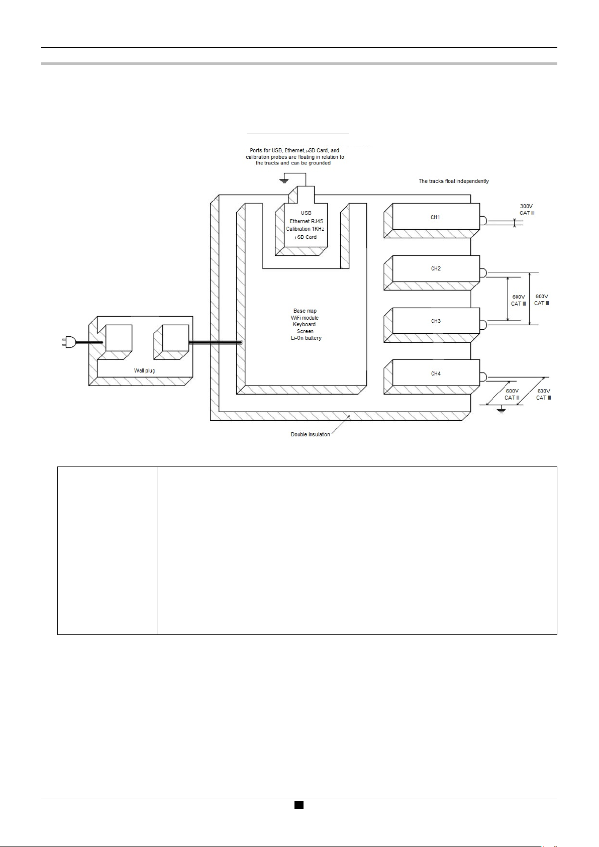
1.5. Isolation of the channels
ScopiX has 2 or 4 channels that are isolated from each other and from earth (600V CAT III):
ScopiX electrical dagram:
General
Frame grounds
isolation
Making measurements in systems where the circuits may be at different potentials can be
very dangerous, due to short-circuits via the instrument or from the potentials themselves.
The digital isolation of the grounds uses the same input terminals and acquisition systems
for the oscilloscope and multimeter modes, making it possible to change from one
instrument to the other without changing the measurement connection.
Since the 3 channels are isolated from each other, you can safely set up one or two
channels with a voltage-to-ground output and the other channel(s) with low current or
voltage input.
Probix accessories provide continuous information about the limits of the instrument
(insulation voltage, rated maximum voltage).
Page 9

General
9
1.6. Probix accessories
1.6.1. Probix
ScopiX uses Probix intelligent probes and sensors,
which are recognized automatically when connected. When
a probe or sensor is connected to the oscilloscope, a safety
message about the probe/sensor indicates:
maximum input voltage as a function of the category
maximum voltage with respect to earth as a function
of the category
maximum voltage between channels as a function
of the category
sensor/probe type
elementary specifications
suitable safety leads
For the safety of both you and the instrument, read and carefully follow this information.
The trace color of the signal measured with a given accessory is set in the menu: "Green" "chX" "Probix". An
interchangeable elastic or plastic ring is used to associate the color of the probe and the color of the trace. Scaling and units
are configured automatically by the Probix system, allowing rapid measurements with no risk of error.
1.6.2. Rapid, error-free measurements
The Probix system ensures rapid and error-free setting up of the instrument, which is essential for instruments used for
troubleshooting. Standard BNC accessories and banana cables can be connected using the safety adapters provided. An
interchangeable plastic ring is used to match the color of the accessory to its channel. The power supply for the sensors is
provided by the oscilloscope.
(1) (2) (3)
Display of the:
max. input voltage (1) with respect to earth
floating voltage (2)
voltage between channels (3)
according to the installation category, the type or reference of
the sensor, and a designation of the main characteristics.
floating between channels with respect to earth
(2) (3) (1)
Page 10
10
1.6.3. Auto scale
A B
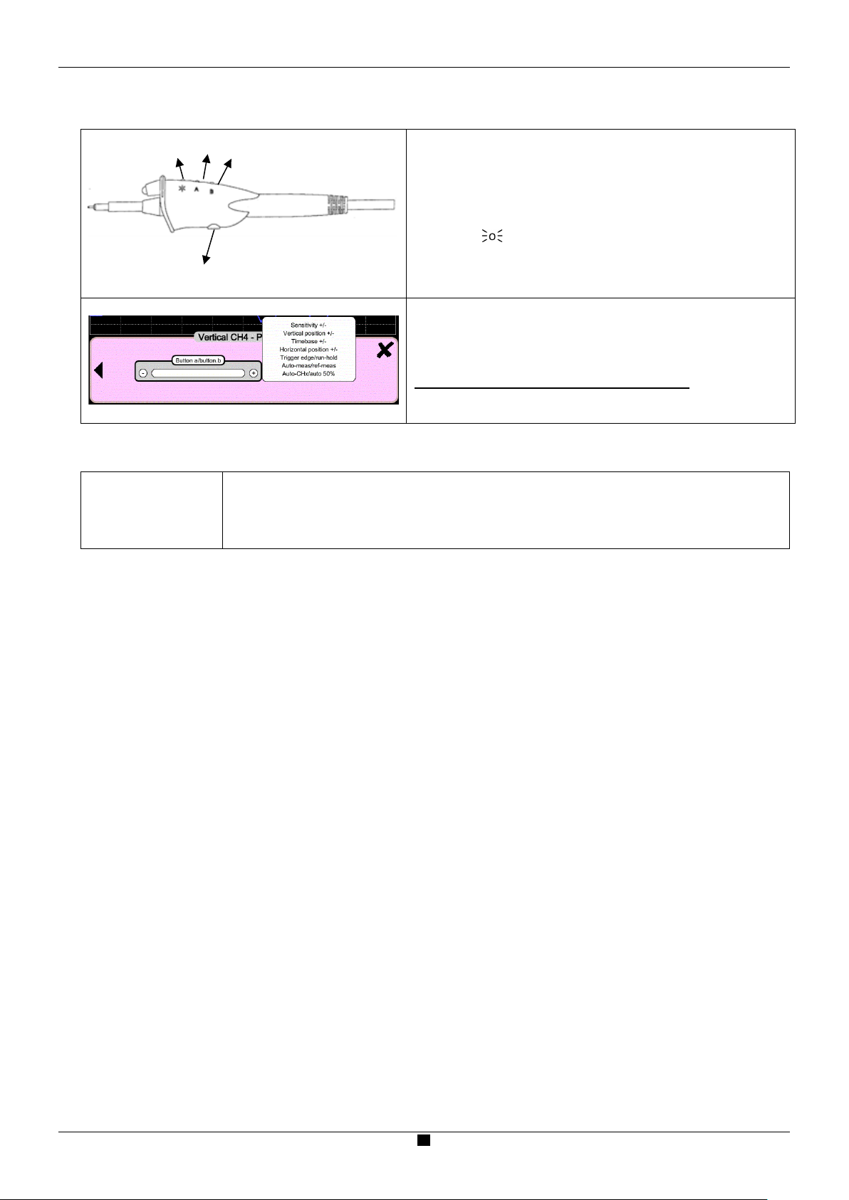
RF compensation
Some Probix probes have buttons with programmable settings:
o
1.6.4. Safety message
The HX0030 probe has three directly accessible control buttons:
Button A (programmable) modifies settings for the
connected channel
Button B (programmable) modifies settings for the
connected channel
Button controls the backlighting of the measurement
zone
At the time of connection, all preferred settings stored in the
accessories (assignments of buttons A and B + color) are
automatically reactivated. They can be modified by pressing the
zone shown in the illustration to the left.
Configuring channels and managing sensors
The coefficients, scales, and units of the sensors and the
configurations of the channels are managed automatically.
General
Accessory
identification
and safety
management
1.6.5. Power supply to the accessories
The oscilloscope supplies power to the Probix accessories.
Probes and sensors are automatically recognized when connected. The instrument identifies the
probe/sensor and provides information about its characteristics. This helps ensure safety.
Page 11

Description
11
Hard enclosure covered with
elastomer, rated to IP54.
Probix terminal
block
Stylus for touch screen use
Color screen
Display of the applied signals,
adjustment
The main command
functions can be modified by
using the
Silicone keypad
The screen is divided into
channels.
Power supply
Li-Ion battery pack, 10.8V
Battery charger port
Stand (shown in closed position)
2.1. Front panel
2. DESCRIPTION
accompanied by all
parameters.
the touch screen
stylus provided.
Icons provide easy function selection.
functional zones: display of the
zoom simultaneous with waveform,
automatic measurements and
cursors, FFT function with timedomain signal.
Each channel and its parameters
are identified by an identical color
on a black ground for better
visibility.
The colors are optimized to identify
30 keys provide direct
access to the main commands.
2.2. Rear panel
Safety markings
"Use only the probes and leads
specified in the operating manual.
The insulation level varies according to
the probes and accessories used.
Refer to the operating manual and the
safety information on screen.
Disconnect the leads, the probes, and
the power supply before replacing the
battery."
Page 12

12
2.3. Touch screen and stylus
Display
The screen:
- touch-operated
- color
- water- and dust-resistant
- responds to any form of pressure by any pointing resource, such as a stylus or bare or
gloved hand
Intuitive icons for ease of use.
Each channel and its parameters are identified by matching color on a black ground for
better legibility.
Colors are optimized to facilitate channel identification.
Screen is partitioned according to the functions selected:
- display of the zoom at the same time as the waveform
- automatic measurements and cursors
- FFT function and time-domain signal
Description
Color screen:
LCD WVGA
(800x480)
7 inch
TFT
resistive, color, touch operated (can be
used with protective gloves)
Backlighting by LEDs
Brightness adjustable by the keypad
Light sensor: automatically adjusts
brightness to accommodate ambient
light
Calibrating
the touch
screen
The touch screen can be calibrated from the home window by pressing the key.
Page 13

Description
13
CLIC !
2.4. Accessories
HX0122 strap with
removable grip
Attaching the strap (length adjustable from 16.5 to 23.6” [42 to 60cm]) to the instrument:
1. Attach the strap:
2. Remove the strap:
Stand providing
an angle of 40°
Page 14
Description
14
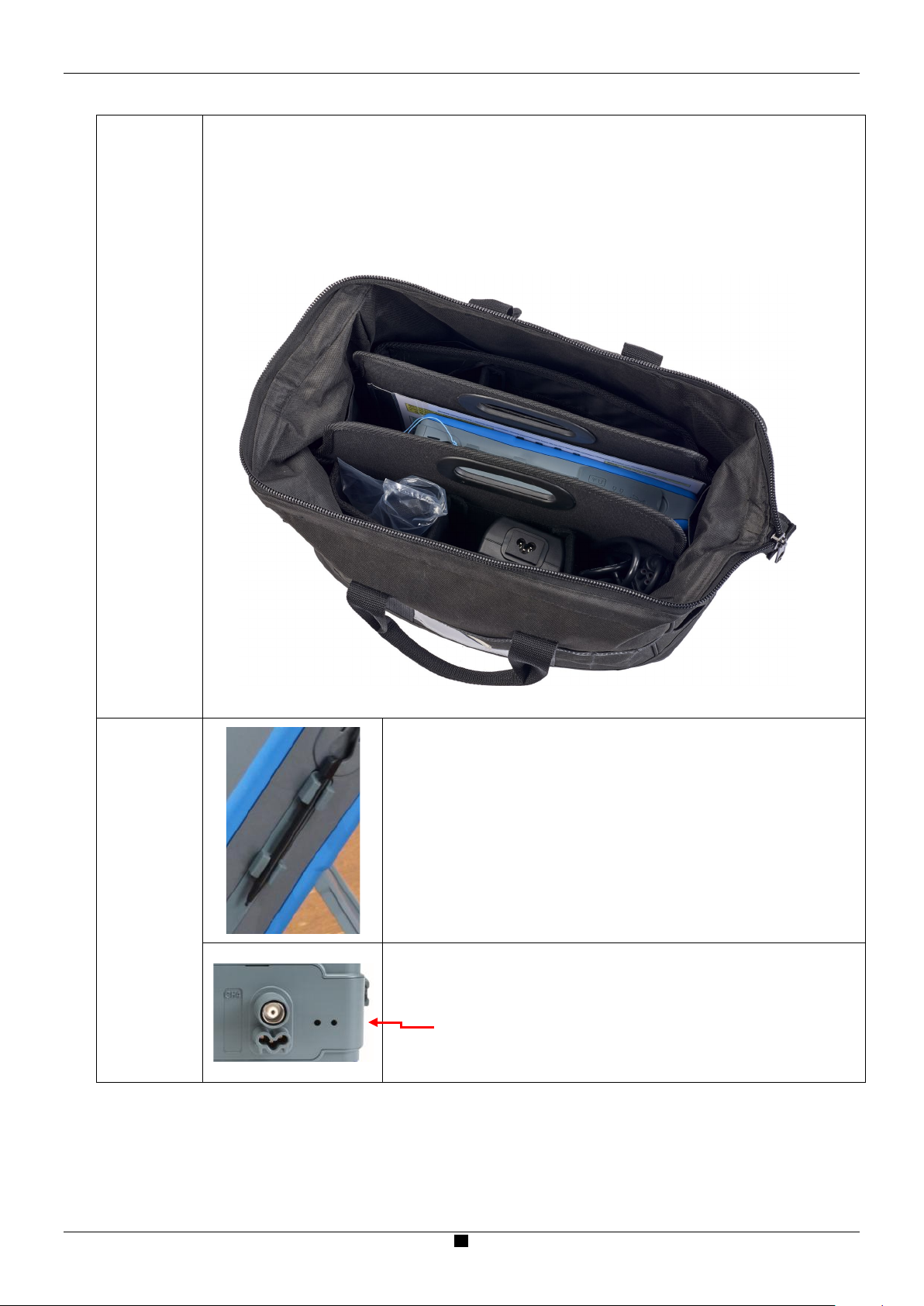
HX0120
carrying
case
The carrying/protection case includes:
waterproof all-terrain bottom
2 handles
shoulder strap
removable interior compartment with 3 storage areas:
- 1 central compartment with plasticized pouch for the ScopiX
- 2 side pockets with 2 adjustable self-adhesive separators for storing accessories
HX0121
stylus
The stylus is stored in the holder on the side of the instrument.
The stylus has an eyelet.
A nylon thread can be passed through it to secure the stylus to the
terminal block:
2 holes, with a thread guide between them, are provided for this
purpose.
Page 15

Description
15
USB connector
RJ45 Ethernet
µSD card
Probe
2.5. Communication interfaces
Communication interfaces
Communication ports are grouped in a
dedicated compartment on the right side
of the oscilloscope and protected by a
removable cover.
Communication type
(USB
Type B, 12Mb/s)
Type B USB (peripheral) for communication with a PC
RJ45 Ethernet wired peripheral
WiFi (default state is inactive) for communication with a PC or with a network
printer
High-capacity µSD for data storage
The memory icon appears in one of three colors (refreshed every 5
minutes) to indicate the presence of the SD-Card and the amount space left on the
card or the internal memory.
The general configuration of the communication interfaces appears when you
select the icon. By default, the WiFi link is inactive.
Hard-wired ETHERNET LAN network (manual/automatic configuration)
WiFi to communicate with a PC or (in an Android environment) with a tablet or
smartphone
Type B USB to connect a PC and exchange files or control the instrument
connector
(10/100
BASE-T)
(SD, SDHC,
SDXC)
calibration
lugs
Page 16

16
3. GETTING STARTED
3.1 General principles
Dialog boxes are displayed at the bottom of the screen. They do not overlap the graph display area, providing an
unobstructed view of the user's action on the channel. (Only adjustments related to the displayed graph remain
displayed.) However, in some cases a virtual keypad appears to enable entering alphanumeric content; this keypad
appears in the center of the screen and covers the graph display area.
The button at top right closes the currently open dialog box.
Changes to dialog box settings take effect immediately (no confirmation required).
Selecting displays the online Help (common to all modes). The Help explains the keys of the keypad: pressing
any key of the keypad displays the Help menu of the key pressed, without starting the function associated with the key.
The name and icon of the key are displayed above the explanation.
To exit Help, point the stylus to the Help window.
The operating mode is multilingual; screen shots in this manual are in English.
3.2 ON/OFF key
Getting Started
3.3 Screenshot key
Saves screen shots in the "Screenshot" folder.
Accessible in the following modes:
Files are named:
SCOPIX_date_hour-minute-second.png
in the internal memory or on the connected µSD
Card.
3.4 Full Screen key
Pressing this key turns ON the instrument (orange LED lights).
A short press switches the instrument to standby (orange LED blinks).
A long press saves the configuration and turns OFF the instrument.
oscilloscope
multimeter
logger
harmonic analyzer
Toggles the display mode between normal and "full
screen."
The screen is organized to provide optimal area for
displaying graphs.
Blanking:
menu bar
parameters of the time base traces
bargraph
from the home screen, this key allows calibration of
the touch screen.
Page 17
Getting Started
17
Action
Result
(on the screen)
printing
GPL2, LGPL)
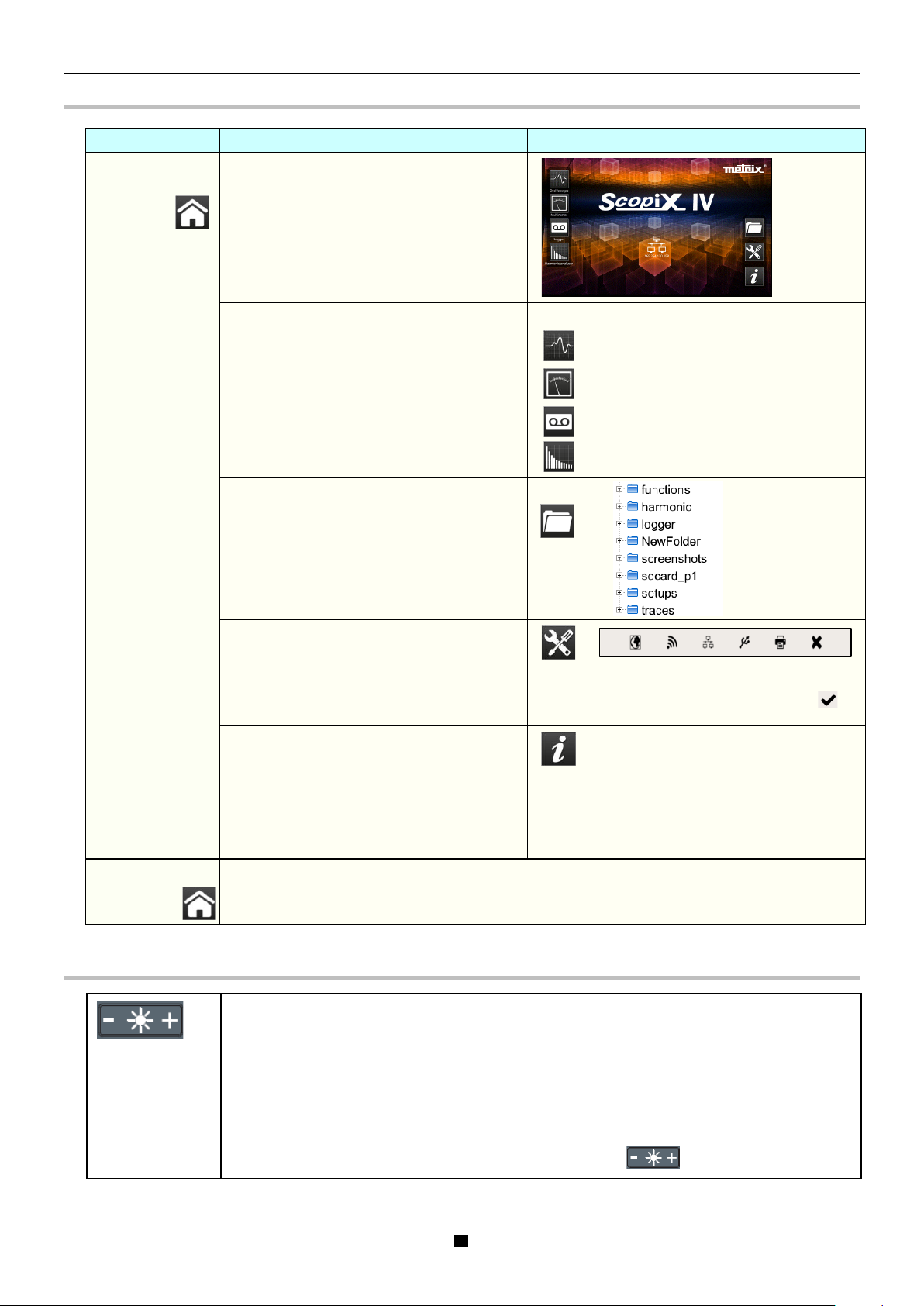
Click the "HOME"
3.5 HOME key and icon
Press the HOME
key on the keypad
Return to the home screen from a
measurement session.
Directly access the instrument's operating
modes:
- oscilloscope
- multimeter
- LOGGER
- harmonic analyzer
Access the internal file management system
and the SD-Card (a file contains a saved
object).
icon on the
screen
3.6 Brightness key
Access the system parameters:
set time and language
WiFi
network
Access the following information:
serial number of the instrument
hardware version
software version
texts of the licences of the various
embedded software modules (GPL,
Return to the home screen, at any time during your browsing.
Adjusts the brightness of the screen (LED backlighting):
min. level 0%
max. level 100%
You can adjust the brightness according to your exposure:
lower press "-"
higher press "+"
The available steps are 25%, 37%, 50%, 62%, 75%, 87%, 100%.
Note: Brightness adjusted automatically until the key is pressed
Page 18

18
"Home"
ON/OFF key
Brightness
Full screen
Screen shot
Reference
Autoset
4.1 SCOPE mode
OX 9304 Functional Description
4. OX 9304 FUNCTIONAL DESCRIPTION
4.1.1 Keys/ active keypad
4.1.2 Reference Memory adjustment
Automatic
measurements
Reference
measurements
of the
Cursors
In oscilloscope mode, pressing this key freezes
the traces on the screen. The graph is displayed
in a darker shade of the channel color as a
reference to be compared to a new acquisition.
The reference memories are accompanied by
their reference numbers.
Pressing this key again erases reference
memories.
This memory is not saved and will be lost
when you exit Oscilloscope mode.
4.1.3 AUTOSET adjustment "Magic Wand" key
memory
Horizontal
time base
Zoom
Vertical
adjustments
Triggering
Automatic optimum adjustment of the AUTOSET of the channels to which a signal is applied.
The adjustments are:
coupling
vertical sensitivity
time base
slope
positions
triggering
The signal having the lowest frequency is used as triggering source.
If no trace is detected on the inputs, autoset is aborted.
A simultaneous press on + assigns the corresponding channel as triggering source.
Page 19

OX 9304 Functional Description
19
4.1.4 MEASURE adjustment
Activates/deactivates window
that displays the 20 automatic
measurements of the reference
trace.
By default, cursors are
activated with automatic
measurements.
Activates the 20
automatic
measurements of the
4 traces with
displacement by
"scrolling".
Selects, from among displayed traces, the reference trace for automatic and manual
measurements. The reference channel is identified by a circle in the color of the channel in the CHx
or Fx zone.
Activates/deactivates display cursors used for manual measurements.
In automatic measurement mode, cursors cannot be deactivated.
The vertical and horizontal cursors can be moved on the touch pad via the stylus.
The measurements made in position T (period), "dt" (time difference between the two cursors), 1/dt
(difference as a frequency, in Hz) and "dv" (voltage difference between the 2 cursors) are reported
in the status area. A phase cursor Ph (in °) displays a value for the angle between T and the
reference.
4.1.5 HORIZONTAL time base adjustment
a) from the keypad
Increases/decreases the coefficient of the time base by successive presses (T/DIV).
After a Zoom, the "Z-Pos." adjustment modifies the position of the screen in the acquisition
memory (upper part of the screen).
Activates/ deactivates the horizontal
"Zoom" function
A waveform screen is displayed at the top
of the screen, with the zoomed portion in
the main display area.
By default, the zoom is around
samples at the center of the screen, but
the display area can be moved.
A display area can be zoomed by tracing
a rectangle around the area to be
enlarged using the stylus on the touch
pad.
The sensitivity values, time base, and
horizontal and vertical positions are
recalculated automatically.
Page 20

20
b) from the screen
1. Y(t): time-based view
of a waveform
OX 9304 Functional Description
Click at top right in the screen, on the Time Base zone (see the image to the left).
Description below of the Y(t) - Y(f) - XY display modes
Settings from 1ns to 200s
No averaging
Averaging coeff. 2
Averaging coeff. 4
Averaging coeff. 16
Averaging coeff. 64
Vector A vector is plotted between samples.
Envelope The minimum and maximum observed at each horizontal position
The entire
acquisition
Increased time resolution of a trace for a periodic signal. When this option is checked, the
signal can be averaged.
For time bases finer than 100µs/div. (without active zoom mode), the signal displayed is
reconstituted from several acquisitions. The time resolution can be as fine as 40ps.
If the signal is not repetitive, do not use this option. The time resolution will then be
±1ns.
Note that if this choice is checked, signal reconstruction can take an extended time.
The following parameters influence this time:
time base
frequency of recurrence of the trigger
activity of the Averaging mode
During this reconstruction, the signal must be stable (amplitude, frequency, waveform). To
speed up the reconstruction following a change in the signal, stop the acquisition, then
restart: Stop/Run.
Selects a coefficient to calculate an average on the displayed
samples (for example to attenuate random noise in a signal).
For the averaging coefficient to be taken into account in the
representation of the signal, the "Repetitive signal" option must be
selected.
The calculation is performed using the following formula:
Pixel N = Sample*1/Averaging rate + Pixel N-1
(1-1/Averaging rate):
Sample Value of the new sample acquired at abscissa t
Pixel N Ordinate of the pixel at abscissa t on the screen,
at instant N
Pixel N-1 Ordinate of the pixel at abscissa t on the screen,
at instant N-1
on the screen are displayed. Use this mode to display a variation in
time or of amplitude, or a modulation.
The whole of the acquisition (100,000 samples) is displayed on the
screen and a vector is plotted between samples. Use this mode to
display all details of the acquisition. This function can be used on a
memory or on a graph already acquired.
Page 21

OX 9304 Functional Description
21
2. Y(f) = FFT (Fast
Fourier Transform)
Displays extreme values of the signal, acquired between two samples of the acquisition
memory. This mode:
detects a false representation due to undersampling
displays short-duration events (Glitch, ≤2ns).
Whatever time base is used, with its corresponding sampling rate, events having a short
duration (Glitch, ≤2ns) are displayed.
ROLL: Automatic on time base > 100ms, single
In single-shot mode, if the time base exceeds 100ms/div, the new samples are displayed
as soon as they are acquired. In addition, ROLL mode is activated when acquisition
memory is full (scrolling of the trace from right to left on the screen).
In triggered mode, save/retrieve can be used to record acquisitions in .trc format to the
"Traces" directory. This lets you store several rare events in the file system and analyze
them later.
Fast Fourier Transform
calculation
The Fast Fourier Transform (FFT) is used to calculate the discrete representation of a
signal in the frequency domain from its discrete representation in the time domain. It is
calculated on 2500 points. It can be used in the following applications:
measure harmonics and distortion of a signal
analyse pulse response
search for a noise source in logical circuits
1
)
(
=
x
N
x (n): a sample in the time domain
X (k): a sample in the frequency domain
N: resolution of the FFT
n: time-domain index
k: frequency index
(n)
exp j
nk
N
[0 (1)]
Page 22

OX 9304 Functional Description
22
Width of the main lobe
Max. amplitude of the
rectangular
0.88
-13
Hamming
1.30
-31
Hanning
1.44
-43
Blackman
1.64
-58
Flat top
3.72
-93
Rectangle
Hamming
Hanning
Blackman
Flat top
Before calculating the FFT, the oscilloscope weights the signal to be analyzed by a
window that acts as a bandpass filter. The choice of window type is essential to
distinguish the different spikes of a signal and make accurate measurements.
Time representation
gnal to be analyzed
of si
Weighting window
Weighted signal
Frequency representation of
the signal calculated by FFT
The total duration of the study interval results in a convolution in the frequency
domain of the signal with a function sinx/x.
This convolution modifies the graphic representation of the FFT because of the
c
haracteristic lateral lobes of the sinx/x function (unless the study interval contains
an integral number of periods).
Five weighting windows are available. The menus appear immediately when you
select FFT menu:
Type of window
at 3dB down (bin)
secondary lobe (dB)
Effects of undersampling on the frequency representation:
If the sampling frequency is too low (less than twice the cutoff frequency of the
signal to be measured), the high-frequency components are undersampled and are
“aliased” (frequency-shifted) in the graphic representation of the FFT.
The Autoset function is active. It avoids the undersampling issue and adapts the
horizontal scale to make results easier to view.
The Zoom function is active. The zoom affects the graphic representation of the FFT
but does not change the conditions of acquisition (TB + depth).
Page 23

OX 9304 Functional Description
23
3. XY
Horizontal unit: This is displayed in place of the time base and is calculated from the
sweep coefficient:
Unit in
Vertical unit: The sub-menus provide two possibilities:
a) Linear scale: by selecting the FFT menu, then linear scale
in (V/div) =
b) Log scale: by selecting the FFT menu, then log (logarithmic) scale
dB/div. = by assigning 0dB to a signal of 1 RMS amplitude division in the time
representation
The vertical position indicator of the representation is at –40dB.
Hz
(
) =
div
unit of the signal in its time-domain representation (V/div)
12.5
Sweep coefficient
2
Assign signals to the horizontal (X) and vertical (Y) axes.
Selected via "+/-".
Each axis is graduated in 8 divisions.
No, 2, 4, 16, 64
Vector, Envelope, Entire acquisition
Settings from 1ns to 200s
Increases the time resolution of a trace for a periodic signal
Page 24

24
4.1.6 Adjustment of the amplitude of the "VERTICAL" signal
It takes into account the parameters of the "Vertical scale" menu.
a) from the keypad
Select channel
Activate channel
De-activate channel
Adjust the vertical sensitivity of the last channel selected:
Increase the vertical sensitivity
Decrease the vertical sensitivity
The sensitivity is displayed in the parameter display area of the channel.
Adjusts position of the selected graph on the screen:
Move up
Move down
OX 9304 Functional Description
Select, by successive presses on the input coupling, "AC", "DC" or "GND" of the last channel
selected
Modification of the coupling AC - DC - GND:
Activates or deactivates the horizontal
division by 4 of the display zone.
Activation of the "Full Trace" function is
indicated by:
After this function is activated, traces can
be moved vertically in their zones.
AC blocks the DC component of the input signal, attenuates signals below 10Hz.
DC transmits the DC and AC components of the input signal.
GND the instrument internally connects the input of the selected channel to a reference
level of 0V.
continuous horizontal line between
the display zones
horizontal division of the graticule
by 2
Page 25

OX 9304 Functional Description
25
BW limit.
b) from the screen
Example:
Defines the vertical scale of the selected channel.
This produces a reading of the direct measurements of the quantity analyzed and
of its unit.
Coupling: AC AC
DC DC
GND GND
Coefficient: Assigns a multiplier coefficient to the sensitivity of the selected
channel. Select this via the stylus, on the digital keypad of the "Coefficient" zone,
and validate by pressing .
The sensitivity displayed in the selected channel’s parameters will be modified as
a function of this coefficient.
Unit of measurement: Defines vertical scale unit of the selected channel. Select
the “measurement unit” zone and enter the name using the stylus in the table of
available characters (not more than 3).
The vertical scale unit appears in the modified channel’s parameters display.
Bandwidth limit, 3 filters can be selected: 15MHz, 1.5MHz and 5kHz
BX limit is adjusted only from the adjustment menu of the channel, by clicking it
with the stylus
Limits bandwidth of the channel and of its triggering circuit, to moderate display
noise and spurious triggerings. The bandwidth of each channel can be limited to
5kHz, 1.5MHz, or 15MHz.
The bandwidth limit of a channel appears in the command zone by the parameter
Selection of the color:
- red
- green
- magenta
- blue
Page 26

26
PRETRIG acquisition
4.1.7. Adjustment of the triggering level "TRIGGER"
a) from the keypad
Adjusts the triggering level on the mean value of the signal (50%) without modifying the coupling
of the trigger. Pressing this button combined with a CHx key starts the same function, but first
selects the corresponding channel as triggering source.
Sets the triggering slope (positive or negative). The slope is displayed in the status zone.
Cycles through acquisition mode options:
Single-shot = SINGLE (sgl)" on the screen
Triggered (trig'd)
Automatic (Auto) = REFRESH
SINGLE-SHOT mode:
A single acquisition triggered by the trigger by pressing the RUN HOLD key is allowed.
For another acquisition, the triggering circuit must be reset by pressing the RUN HOLD key.
The ROLL mode is automatically activated.
TRIGGERED mode:
Updates the screen only when a triggering event linked to the signals present on the inputs of
the oscilloscope (CH1, CH2, CH3, CH4) occurs.
In the absence of any triggering event linked to the signals present on the inputs (or in the
absence of signals on the inputs), the trace is not updated.
OX 9304 Functional Description
AUTOMATIC mode:
Updates the screen even if the triggering level is not detected in the signals on the inputs.
In the presence of a triggering event, the refreshing of the screen is managed as in the
"Triggered" mode.
Acquisitions in TRIGGERED and AUTOMATIC modes are enabled or stopped.
The triggering circuit in SINGLE-SHOT mode is reset.
Acquisition is started according to the conditions defined by the acquisition mode
(SINGLE REFR).
The status of the acquisition is indicated in the status zone:
- RUNNING started
- STOP stopped
-
Page 27

OX 9304 Functional Description
27
b) from the screen
1. Edge
Selects a channel as triggering source:
E.g. CH4
Selects the filter of the main triggering source:
AC AC coupling (10Hz to 300MHz):
blocks the DC component of the signal.
DC DC coupling (0 to 300MHz):
passes the whole signal.
LF Reject Rejection of source signal frequencies < 10kHz:
facilitates the observation of signals having a DC
component or an undesirable low frequency.
HF Reject Rejection of source signal frequencies >10kHz:
facilitates the observation of signals containing high-frequency noise.
Triggering source
The symbol indicating the triggering level on the graph also indicates the coupling:
DC
AC
LF Reject
HF Reject
Selection of the triggering slope:
positive-going triggering slope Rise edge +
negative-going triggering slope Fall edge -
The selected triggering slope is displayed in the status zone.
0.00V Adjusts triggering level
The triggering level displayed in the current value display zone. It can then be finely
adjusted.
No Hysteresis ≈ 0.5 div.
Yes Hysteresis ≈ 1.5 div.
100 µs:
disables triggering for a preset duration
stabilizes triggering on pulse trains
Pointing to this field opens on screen a virtual digital keypad for direct entry of the
value.
Page 28

OX 9304 Functional Description
28
triggers on a pulse if its duration is outside the limits defined by
T1
T2
for direct entry of the
2. Pulse
Selects the width of the “triggering on pulse” value:
The edge is selected either in the "Trigger" tab or from the keypad and defines the
limits of the analysis:
edge defines a pulse between and
edge defines a pulse between and
In all cases, the actual triggering is on the end-of-pulse edge:
t>T1 triggers on a pulse if its duration is greater than setpoint T1
t<T1 triggers on a pulse if its duration is less than setpoint T1
t>T1 and t<T2 triggers on a pulse if its duration is between T1 and T2
t<T1 or t>T2
Adjusts the qualification source:
3. Delay
Qualifier
0.00V Triggering level
100 µs Adjustment: disables triggering for a preset duration and (among other
things) stabilizes triggering on pulse trains.
Pointing to this field opens a virtual
digital keypad
value.
and
Page 29

OX 9304 Functional Description
29
facilitates the observation of signals containing high-frequency noise.
Triggering
delay
Trigger
Adjustments on the
triggering source
Selects delay:
Pointing to this field opens a virtual
digital keypad for direct entry of the
value.
Selection of triggering on edges with delay:
The delay is triggered by the auxiliary source.
Actual triggering occurs on the next event in the main source after the end of the
delay.
Selects filter of the auxiliary triggering source:
AC AC coupling (10Hz to 300MHz):
blocks the DC component of the signal.
DC DC coupling (0 to 300MHz):
passes the whole signal.
LF Reject Rejection of source signal frequencies < 10kHz:
facilitates the observation of signals having a DC
component or an undesirable low frequency.
HF Reject Rejection of source signal frequencies >10kHz:
Positive-going triggering slope of the auxiliary source
Negative-going triggering slope of the auxiliary source
No Hysteresis ≈ 0.5 div.
Yes Hysteresis ≈ 1.5 div.
Page 30

OX 9304 Functional Description
30
4.Counting
Qualifier
Counting settings
Selects triggering on edge with counting of events.
Selects adjustments on the qualification source:
100 µs Disables triggering for a preset duration and (among other things)
stabilizes triggering on pulse trains.
Pointing to this field opens a virtual digital keypad for entering the value.
The counting is triggered by the auxiliary source; the main source serves as counting
clock. Actual triggering occurs on the next trigger event in the main source after the
end of the count:
3 Selects number of events.
Trigger
Pointing to this field opens a virtual digital keypad for entering the value.
Selects adjustments on the triggering source:
Selects filter of the auxiliary triggering source:
AC AC coupling (10Hz to 300MHz):
blocks the DC component of the signal.
DC DC coupling (0 to 300MHz):
passes the whole signal.
LF Reject Rejection of source signal frequencies < 10kHz:
facilitates observation of signals having a DC
component or an undesirable low frequency.
HF Reject Rejection of source signal frequencies >10kHz:
facilitates the observation of signals containing high-frequency noise.
positive-going triggering slope
negative-going triggering slope
The triggering slope selected is indicated in the status zone.
600mV Triggering level
No Hysteresis ≈ 0.5 div.
Yes Hysteresis ≈ 1.5 div.
Page 31

OX 9304 Functional Description
31
4.1.8. MATHEMATICAL function, from the screen
Defines, for each trace, a mathematical function and vertical scale
Equation editor (functions, in the channels or simulated, programmable as F1, F2, F3, F4):
Addition
Subtraction
Multiplication
Division
Complex functions between channels
Simple
functions
Complex functions
Example:
Addition between channels
Example:
Production of a damped sinusoidal trace
from predefined functions
math1 = sin (pi*t/divh(1))*exp(-t/divh(6))*divv(4)
"sin (pi*t/divh(1))" changes the number of periods.
"exp (-t/divh(6))" changes the damping level.
Defining a complex
function
8 predefined mathematical functions can be used:
divh(
divv(
step(
sin(
cos(
exp(
log(
sqrt(
() t = abscissa of the sample in the acquisition
memory divh(1) is equivalent to 10,000
samples (points) = 1 horizontal div.
"horizontal division"
"vertical division"
"on" using "t" ()
"sine"
“Cosine"
"exponential"
"logarithmic"
"square root"
Page 32

32
4.1.9. AUTOMATIC measurements, from the screen
vmin
trise
vpp
wplus
vhigh
period
vrms
dcycle
Opens the "Automatic measurements"
Menu window of the channel
Opens the "Automatic measurements"
Menu window of the 4 channels
OX 9304 Functional Description
Measurements are made and refreshed on the selected reference trace. All measurements
that can be made on this trace are displayed. (- . - -) is displayed for measurements that
cannot be made.
To close the window, point to
with the stylus.
All 20 measurements selected will be displayed in the status zone at the bottom of the screen,
on a background the color of the channel:
minimum peak voltage
vmax
maximum peak voltage
peak-to-peak voltage
vlow
stabilized low voltage
stabilized high voltage
vamp
vrms_c
amplitude
RMS voltage determined in the
measurement interval
RMS voltage determined on a whole
number of cycles
vavg
mean voltage
sum
summation of the instantaneous
values of the signal
npulses
over_pos
over_neg
rise time
tfall
fall time
positive pulse width
(at 50% of Vamp)
wlow
negative pulse width
(at 50% of Vamp)
period
freq
frequency
duty cycle
number of pulses
positive overshoot
negative overshoot
Measurement
conditions
The measurements are made on the part of the trace displayed on screen between cursors T1
and T2.
Any modification of the signal entails an update of the measurements.
They are refreshed as the acquisition proceeds.
The accuracy of the measurements is optimum when at least two complete periods of the
signal are displayed.
Page 33

OX 9304 Functional Description
33
T = 1/F
W+
W-
Vmax
Vhigh
Vlow
Vamp Vpp
>
5%
T
Trise
Tfall
0%
10%
50%
90%
100%
>
5
%T
Vmin
t0t1t2 t3t4t5
t
6
Va
v
g
1/2
2
GND
ni
0i
i
])y(y[
n
1
−
∑
=
=
= Vrms
)y(y
GND
ni
0i
i
n
1
−
∑
=
=
= Vavg
∑
=
=
×
n
i
0i
)(y
t
δ
i
=
Vsum
Automatic
measurements
Positive overshoot = [100 * (Vmax – Vhigh)]/Vamp
Negative overshoot = [100 * (Vmin – Vlow)]/Vamp
4.1.10. Backup
YGND = value of the point representing zero volts
Pressing this key displays the screen shown below:
Use this function to record (in local memory or on an µSD Card) the following:
traces displayed
mathematical functions
configuration of the instrument
These files can be restored from the file manager.
Page 34

OX 9304 Functional Description
34
4.2 Multimeter mode
4.2.1 Keys/keyboard active in Multimeter mode
The ScopiX has a Multimeter function with 8000 display points. It has as many independent multimeters as there are
channels in the Oscilloscope mode (2 or 4), with the same function as in the Oscilloscope mode: Probix.
Coupling:
If a channel is activated and selected, pressing this key changes the input coupling of the
channel. With successive presses, the coupling runs through the following settings:
AC AC <5kHz AC <625 AC+DC AC+DC <5kHz AC+DC <625Hz DC.
Adjusting the coupling is not possible in the following modes: Ohmmeter, Capacitance meter,
Continuity, Test of component, Wattmeter.
Modification of the coupling (AC, DC, AC + DC) in amplitude measurement
AC: AC voltage measurement
DC: DC voltage measurement
AC + DC: AC voltage measurement with a DC component
If the channel measures AC or AC + DC voltage, you can filter the signal with a low-pass
analog filter having a cutoff frequency of 5kHz.
The other filter proposed is a digital filter at 625Hz; if this filter is chosen, the 5kHz analog filter
is also activated.
Low-pass filter
Cutoff frequency .......................... 625Hz
Order............................................ 94
Bandwidth ripple………………….. 0.5dB
Transition band ........................... 0.02
Stopband attenuation .................. 50.0dB
Manual measurement range.
De-activates Autorange and returns to manual mode.
The Autorange function is active by default; pressing this key changes to manual range.
Page 35

OX 9304 Functional Description
35
4.2.2 Icon/screen of the Multimeter mode
The channel is displayed in the color defined in Oscilloscope mode. Inactive channels are displayed in white.
Display screen:
4 measurements
4 channels
Several types of measurement are possible on CH1; the other channels are voltmeter channels
Channel 1
only. A display zone is reserved for each channel. Each displays the following information:
CH1, CH2, CH3, or CH4 as Voltmeter 2
Volt: no display of the symbol (lower part of the CH zone)
Ohmmeter and audible safety beep
Continuity
Capacitance meter
Test of component
The display of the measurement automatically takes into account the characteristics of
Probix (in particular for temperature measurements by PT100/TK).
Autorange
Main
measurement
A long press on channel CH validates or invalidates autorange of the channel.
If Autorange is active, the range is displayed in white in a colored square.
If the channel is activated, the measurement result is displayed. Otherwise the message "- X -"
occupies the unused space. If "-----" is displayed, measurement is not possible: it is outside the
authorized range, and "OL" is displayed.
Unit
Contains the measurement unit associated with the current measurement range according to
the Probix used and the type of measurement.
The unit cannot be configured in multimeter mode.
Page 36

OX 9304 Functional Description
36
Secondary
measurements
If no display is selected, or if no display is possible (e.g. frequency measurement of a DC
signal, etc.), the string '-----' is displayed.
If the channel is not selected, the string '-X-' is displayed. If the signal is outside of the range:
"OL" for overload is displayed.
Frequency
Statistics
Relative mode
For an AC amplitude measurement,
displays frequency of the measured
signal (if possible and coherent) in each
channel.
Displays Min and Max values of
measurements for each channel.
Displays difference in each channel.
This is the difference between the
measured value and the value displayed
when this key was pressed.
4.2.3 Adjustments of the VERTICAL menu
Activates/de-activates parameters of channels CH1, CH2, CH3, CH4 independently of one
another
Parameter types determined by the connected Probix (adjustment in oscilloscope mode)
Quantity displayed depends on:
- type of measurement selected:
amplitude (available on all channels)
ohmmeter
continuity
capacitance meter
- Probix PT100/TK temperature probe (available on all channels)
- Probix probe connected to the input
- parameters defined in the vertical parameter zone (if they have been modified since the
connection of the Probix probe)
For the ranges available according to the type of measurement, refer to the technical
specifications, "Multimeter" function.
Changes manual range.
RUN Start of measurements
HOLD Freeze of the measurement
Page 37

OX 9304 Functional Description
37
4.2.4 Power measurement
Display
Selecting
distribution
network type and
power parameters
The following secondary measurements are
available in this quantity:
Single-phase
1
=
Three-phase without neutral (two-wattmeter method)
Available only for 4 channel instruments
1
=
(12() + 32() ())
3
=
(12() 32() ())
() ()
MIN/MAX
relative
frequency
Balanced three-phase without neutral (3 wires)
Voltage V3-V1 measurement and measurement of the current on I2
^
)
Balanced three-phase with neutral
=
3 (^
3
=
(U13() ())
3
=
() ()
Page 38

38
Clicking either icon exits Power mode.
Configuration backup.
4.3. LOGGER mode
4.3.1 Keys/keyboard active in LOGGER mode
OX 9304 Functional Description
When you enable LOGGER
mode, a file is automatically
generated. This file records
up to 10,000 measurements
in all active channels:
duration of the record
20,000s, resolution 0.2s.
Page 39

OX 9304 Functional Description
39
Leave enough space for the recording.
4.3.2 Icons/screen in LOGGER mode
LOGGER mode records measurements made in multimeter mode.
Displays graphic time window, showing the time course of the measurements. The most
recent measurements are on the right.
The measurement cursors can be used.
This indicator displays the reference channel:
The time of the
measurements is the
right-hand edge of the
screen (indicated by the
two white triangles).
The file name blinks to
indicate that recording is
in progress.
4.3.3 Principles
sequential recording
Note: In this mode and in VIEWER mode, it is possible to display cursors.
Automatic
(N files of 100,000 measurements) in the memory of the LOGGER directory.
In the event of a power outage, the oscilloscope remains battery powered to keep files
being recorded in memory.
Click these icons twice to exit LOGGER mode.
Opens Help file.
Saves configuring settings in a file.
Page 40

40
4.4. VIEWER mode
OX 9304 Functional Description
File manager
Look-up files in internal
memory and µSD Card
Creates a new directory.
Erases a directory or a file after confirmation.
Duplicates a file.
Renames a file from the alphanumeric keypad.
Displays an analysis file, which opens in the mode recorded (except for .png screenshot
files, which are opened in a specific viewer with file processing tools: erasure, printing,
displacement of windows).
Converts .rec and .trc files into .txt files to allow use in an Excel type spreadsheet.
After conversion, the file appears in the tree, renamed and recorded with the same
name as the original file:
Example on left: .rec file converted to
.txt. file
ScopiX cannot read the.txt file.
Conversion to .txt can take some time.
Wait for the end-of-conversion symbol .
Typical directories
(chronological order)
Exit Viewer mode.
traces: .trcf files of the Oscilloscope mode
setups: configuration files stored in Multimeter, Logger, Harmonic
sdcard_p1: content of the µSD Card (partition 1)
screenshots: .png screen shot of each mode
logger-events: .txt files saved after a search for events
logger: .rec TRACE or .cfg configuration files acquired in LOGGER mode to be
displayed, printed, exported, etc.
You can select several files simultaneously (for deletion or copy).
Page 41

OX 9304 Functional Description
41
VIEWER
Recalling a .rec file
Search for events
"VIEWER" file appears
in the screen
background and the
LOGGER mode is
identified by the icon at
bottom right of the
screen:
Arrows for browsing from one file to another in the same directory.
It is possible to search for events in VIEWER mode. An event is defined by a threshold
and the direction in which it is crossed.
Selects event search parameters.
Selects channel in to search for events.
Selects thresholds L1 and L2.
Selection of search criterion:
< L1: Search for an event less than threshold L1
L1: Search for an event greater than threshold L1
< L1 or >L1: Search for an event less than L1 or greater than L1
<min(L1,L2) or >max(L1,L2): Search for an event less than the smaller of the couple
(L1;L2) or for an event greater than the larger of the couple (L1;L2)
Minimum duration of the event.
Start the search for events.
Page 42

42
Recalling a .png file
OX 9304 Functional Description
Analyze events found. Pressing this icon opens a window containing the events meeting
the search criteria.
When an event is selected, the V1, V2, and T1 cursors appear. The associated
measurements are displayed below the event window.
The event name format is YYYY-MM-DD,HH :MM :SS .s where YYYY-MM-DD is the
date of the record and HH :MM :SS.s is the value of the T1 cursor.
Records the events in .txt format.
These events are recorded in the logger-events folder in File Manager.
A window (which can be moved by cursor) appears at the
top of the screen:
moves from one file to another
moves the window on screen
erases the file, after confirmation
prints the file on the network printer pre-
programmed in "Tools"
closes the .png viewer window
Number of files in the directory
Page 43

OX 9304 Functional Description
43
4.5. HARMONIC mode
4.5.1. Keys/keyboard active in Harmonic mode
4.5.2. Principle
Harmonic mode
Displays the breakdown into harmonics of a voltage or a current of which the signal is
steady-state or quasi-steady-state. It establishes a first diagnostic of the harmonic pollution
of an installation.
This mode displays a graph of the fundamental frequency and harmonics out to the 63rd.
The time base is adaptive; it is not adjusted manually.
This analysis is only for signals with a fundamental frequency between 40Hz and 450Hz.
Only channels CHx (not the functions or the memories) can undergo a harmonic analysis.
The harmonic analysis of 2 (OX 2 channels) or 4 (OX 4 channels) signals can be
displayed simultaneously.
Page 44

44
4.5.3. Icons/screen in Harmonic mode
Displays harmonic analysis of the
selected traces.
The harmonic analyses of traces
ch1 and ch4 appear as solid-color bar
charts, in the color of the trace.
By default, the fundamental is selected
automatically; but the fundamental
frequencies of 50Hz/60Hz and 400Hz
can be programmed manually.
The measurement parameters displayed:
Signal Measurement
- RMS voltage of the signal in V
- total harmonic distortion (THD) in %,
per standard EN50160
OX 9304 Functional Description
Harmonic Measurement
- value in %, ratio
- phase in ° with respect to the
fundamental
- frequency in Hz
- RMS voltage in V
Power harmonics
Solid bars indicate harmonics consumed
and hollow bars harmonics generated.
Example: Harmonic of order 1, incrementing of display of the
harmonic order by + and decrementing by -
Choice of set-up with type of power.
Page 45

OX 9304 Functional Description
45
4.6. Communication
Exits Harmonic mode.
Opens Help file.
The communication interfaces are grouped in a dedicated compartment on the side of
the ScopiX, protected by a removable cover.
You can communicate on several interfaces:
USB type B for communication with a PC
The cord supplied connects to the USB type A port of a PC: transfer of file,
programming using SCPI commands
Ethernet via RJ45 cords or via WiFi for communication with a PC or printing to a
network printer or, in an Android environment, communication with a tablet or
smartphone
High-capacity µSD Card for storing data or loading configurations, available capacity
depending on the type of card
internal disc: 512MB data storage capacity available
By default, files are recorded
in internal memory.
green: memory under 50% full
Files are recorded in the µSD
Card, if it is installed.
orange: memory 50 to 80% full
red: memory over 80% full
Page 46

46
server). An alphanumeric keypad appears.
4.6.1 General parameters
Configuration
Keys
Date/Time
Language
Screen
saver
Auto
off
OX 9304 Functional Description
Updates date (day, month, year) and time (hour, minute, second).
The selection is made by the stylus, using the scroll bars on either
side of the parameters to be adjusted.
The clock starts when the menu is closed.
Selects language used in the menus.
Options include French, English, German, Italian, Spanish, and
others (contact AEMC for the latest additional options).
The screen saver is activated after a specified time, to save power
and extend the life of the screen.
There are 4 options: 15min, 30min, 1h, no saver mode.
The screen is reactivated by pressing any key on the front panel.
The instrument turns OFF after a specified time to save power. In
this case, instrument configuration is saved before power OFF.
There are 4 options: 30min, 1h, 4h, no auto off.
Default setup restores the factory configuration parameters. When
the instrument is turned ON it uses the settings in place the last time
it was turned OFF.
Recall results in the instrument starting up using the default (factory)
configuration.
WiFi configuration. You can:
scan the network at any time, then select the additional page of
settings as soon as the network has been chosen.
modify the fields IP address, subnetwork mask, gateway, then
validate by "Connect". The network is then stored and WiFi
communication is active.
Ethernet configuration, including Atomatic (DHCP) or manual setting
of IP parameters (Address, Subnet Mask and Gateway).
Assigns a link-local address in case of DHCP failure (point-to-point
link).
USB configuration, including manual setting of IP parameters
(Address, Subnet Mask and Gateway).
Programming: cf. installation guide, RNDIS driver for Windows 7
Network printer configuration, including the IP address of the printer
and/or its name if there are several printers in the network (contact
your network administrator to ensure the presence of this type of
Exit the setup menu.
Page 47

OX 9304 Functional Description
47
IP address
Subnetwork
mask
and Gateway
DHC
protocol
MAC address Each ScopiX instrument has a unique factory-configured MAC address. There is one wire
WiFi network selection
An IP address is coded in 4 bytes, displayed in decimal form.
(
: 132.147.250.10).
Each field can be set between 0 and 255; the fields are separated by decimal points.
Unlike the physical address, the IP address can be modified manually by the user or
automatically by DHCP.
Ensure the IP address is unique on your network. A duplicate address could impact
network operation.
If the result of the "LOGICAL AND" between the IP address of the addressee of the
message and the value of the subnetwork mask (SUBNET MASK) is different from the
address of the addressee of the message, the message is sent to the gateway
(GATEWAY), which takes charge of getting it to its destination.
The mask and the address of the gateway can be configured on the instrument.
This protocol automatically sets network access.
A DHCP (Dynamic Host Configuration Protocol) server must be accessible in this network
(contact your network administrator to ensure this is the case).
network MAC address and one WiFi address.
To connect to the WiFi network:
1. Press Scan to manually scan the
available networks (this is done
automatically when the WiFi menu is
opened).
2. Select the SSID network.
3. Enter the network's security key.
4. Select DHCP mode if you want the
network to give you an IP address, or
manual mode if you already have a fixed
IP adress.
5. Click Connect to confirm the settings
and complete connection.
Wire network selection
1. Select DHCP mode if you want the
network to give you an IP address, or
manual mode if you already have a fixed
IP adress.
2. Click Connect to confirm the settings
and complete connection.
"About" - (cf. p.17)
Page 48

48
4.7. Memory
OX 9304 Functional Description
Backup
memory
Available memory
The files are stored in a specific partition.
File system:
1. on an µSD Card; the partitions of the µSD Card are accessible in the sdcard_pX
directory
2. in the local file system
Internal memory of the instrument: 1GB for the file system
"Micro SD" memory card, type: SC (≤2GB)
HC (>2Go ≤32Go)
XC (>32Go ≤2To)
of which the partition(s) are formatted to FAT32.
Memory space
optimization and
consumption
Files of traces acquired in SCOPE mode
Files of traces acquired in LOGGER mode,
Binary format
Configuration files, Binary format
Printing
Files of mathematical functions, Text
format
Files in text format containing a trace
acquired in HARMONIC mode
.trc Size: 400kB per trace stored
(max.: 1.6MB)
.rec Size: 400kB per trace stored
(max.: 1.6MB)
.cfg Size: 1ko
.png Size: <200ko
.fct Size: <1ko
.txt Size: <10ko
Text format files resulting from the
conversion of binary files (.rec or .trc)
.txt Size : variable
Storage options by mode
Type of file
Oscilloscope mode
Multimeter mode
Harmonic mode
Logger mode
Viewer mode
Icon Icon Icon Icon Keypad
Setup.(cfg) Traces.(trc) Math.(fct) Measurement.(txt) Screen shot.(png)
Directory setups traces functions harmonic screenshots
Note: all files in "SCOPIX" including NF are viewable on a PC as an external disk via the USB port.
Ethernet communication is reserved for remote control of the instrument. The SCOPENET application, running on a PC,
uses the files in memory in SCOPIX.
Page 49

OX 9304 Functional Description
49
4.8. Firmware update
Firmware
Periodically, an "update available" message may appear on the home screen, if the
ScopiX is connected to Ethernet or WiFi:
This message indicates update files have been downloaded transparently to the ScopiX :
they are available for an update, which is recommended to obtain new functions, bug fixes;
etc.
Select OK and the update automatically installs the files in the ScopiX.
The duration of the update varies, but is less than 15 minutes.
Follow the directions (see below).
Do not switch off ScopiX during the update.
The files of the internal memory (measurements, screen shots, setups, etc.) are not
destroyed during the update.
For more complete information, go to the support space of our Web site: a manual
update procedure is available.
Update
installation
procedure
1. Connect the ScopiX, preferably to line power.
2. Check "Do you want to install it."
3. ScopiX powers OFF, then back ON.
4. A screen (yellow-white) of which the color varies to represent an action in progress,
with an "update running" message, remains on screen for approximately 8 minutes.
5. ScopiX powers OFF and then back ON.
6. A touch slab calibration procedure screen is displayed: follow the steps by checking
the 4 corners, then the center.
7. The home screen is displayed again: you can view the new system information (date,
version, etc.); the update is complete.
The operating instructions in .pdf format, or any other updated document, can be
downloaded and placed in the file manager.
Page 50

50
4.9. ScopeNet IV
OX 9304 Functional Description
When you have obtained the IP address of the ScopiX
(DHCP or manual) using a browser, type
14.3.250.51/scopenet.html (for example) on your
computer; the screen to the left appears.
JAVA application PC is used to display the
ScopeNet IV page.
Carefully check the installation of ScopeNet to
minimize issues.
To check the instruments connected, do the following:
Press the network icon, in the center of the screen:
the search for instruments in the network (Ethernet
and WiFi) is performed by a specific function. A
series of compatible instruments connected is
displayed (see illustration on left).
The PC environment uses icons in an HMI identical
to the Scopix IV product, with the same access to
the functions and adjustments.
In Oscilloscope mode, ScopeNet IV proposes
adjustments by a right click on the waveform:
RUN/STOP, AUTO/TRIG/SINGLE/AUTOSET and
ZOOM are easy-to-configure parameters.
Example: 2 active channels: CH1 and CH4
2 greyed-out inactive channels: CH2 and CH3
In MULTIMETER mode, the vertical configuration can
be accessed by activating the channel (see top left).
In AUTO RANGE mode (default) you can select from
among a set of ranges (white zone around the quantity)
via the Coupling field (see lower left).
Example: - channel 1 active, AUTO
- channels 2 and 3 inactive, AUTO
- channel 4 inactive, but adjustment of the voltage
ranges is possible.
Page 51

OX 9304 Functional Description
51
File and backup management is performed on the PC.
You can also store data in ScopiX. via USB.
Backup in the various modes (Oscilloscope, Multimeter,
Logger, Harmonic) is possible from the computer
configuration files:
"adjustments" for all modes
"harmonics"
"traces and math" for the oscilloscope mode
The backup is recorded in the ScopiX file system
(internal or µSD Card).
Files stored in ScopiX can be viewed from ScopeNet.
Files are recorded in the directory defined by the type of
record.
Page 52

Waveform Display
52
5. WAVEFORM DISPLAY
5.1 Manual display
To view the signal and project it on the screen, be aware of the following characteristics:
Coupling: note whether the signal is pure AC or has a DC component
amplitude in Volts: defines the signal’s amplitude on screen
frequency or period of the signal: note whether or not it is repetitive
bandwidth: the frequency related to the maximum frequency to measure
Once these characteristics are known, you can configure the channel to display the signal. There are two ways to do this:
using the keypad using the touch screen
5.1.1. Using the keypad
Key Action
1. Connect the Probix probe to a channel input.
2. Press the channel key to refresh it and access configuration.
3. Press this key to select coupling.
4. Press this key to select the vertical sensitivity of the channel or its maximum amplitude
visible on the screen.
5. Press this key to select the desired time base of the channel or the maximum period
visible on screen.
6. Press this key to view signal.
7. The signal appears.
Note
It is not possible to configure the bandwidth of the signal from the keypad.
Page 53

Waveform Display
53
5.1.2. Using the touch screen
Icon Action
1. Connect the Probix probe to the channel input.
2. Click the channel key to refresh it ("channel
activated") and access configuration.
3. Select the coupling type.
4. Press + or - to select the desired sensitivity of the
channel or its maximum amplitude visible on screen.
5. Select the type of bandwidth to obtain the desired
limitation.
6. Press .
7. Click the time base to access the adjustments.
5.2 Autoset
Example
8. Click .
9. Ensure that only "roll" is checked.
10. Select the duration of the time base with + or -.
11. Press .
12. The signal appears.
The "Autoset" key projects the signal you want to display on the screen, along with its
characteristics (refer to "manual" display, §4.1.3.). This enables you to optimize the signal with
one click.
1. Connect the Probix probe to the channel.
2. Press the key above.
3. The message AUTOSET appears on the screen during the configuration process.
This optimizes the display of the signal.
Page 54

54
5.3 Calibrating the probes
the coefficient of the probe into account.
Waveform Display
Step
1.
2.
3.
4
5.
6.
Action
Connect the Probix adapter of an HX0030 probe
having a 1/10 ratio to the CH1 input.
Connect the probe (with its ground) to the calibrator
output (Probe Adjust: ≈3V, ≈1kHz) on the side of the
instrument.
Connect the cold of the probe to the cold of the
calibration output of the probes.
Ensure the 1/10 coefficient of the probe has been
taken into account.
Set the sensitivity of CH1.
Set the coupling of CH1.
Menu CH1
Click the right arrow, Measurement of probe,
select Coefficient: 10,
Validate by clicking
Note: The sensitivity and the measurements take
Menu CH1, Sensitivity/coupling: 500mV/div
or use buttons A and B of the HX0030 probe
or use the keys.
Menu CH1, coupling: AC
or use the key.
7.
8.
9.
If necessary:
Set the sweep rate.
Set the triggering parameters
Set the triggering mode.
Modify the triggering level with the stylus by moving the T (Trigger) symbol on the screen. The triggering level
appears at bottom right on the screen.
Modify the vertical position of the graph by using the stylus to move the 1 symbol, to the left of the screen.
Time base menu: 500µs/div
or or use the keys
Trigg menu: Source: CH1, Coupling: AC, + Edge
+
Trigg Menu by the SGLE REFR. key
use the RUN HOLD key to start the acquisitions
("RUN" mode).
The key can be used to perform these adjustments automatically.
Page 55

Waveform Display
55
Compensation of
the HX0030 probe
Probe overcompensated
Probe correctly
compensated
Probe under-compensated
Probix HX0030 compensation adjustment.
For optimum response, use the knob at the top of the probe to adjust the lowfrequency compensation of the probe so that the plateau of the signal is horizontal.
Page 56

Waveform Display
56
display the list of
5.4 Auto/Cursors/Zoom measurement
5.4.1. Auto
For optimum measurement accuracy, we recommend displaying two complete periods of one or more signals. To do this,
modify the time base using the "horizontal" keys.
There are two ways to start Auto measurements in a channel:
using the keypad: Press the channel key (1 to 4) and the icon shown on the left at the
same time.
using the touch screen: Press the icon shown to the left.
display the list of
signals in this
window:
To start Auto measurements in the 4 channels:
using the touch screen: Press the icon shown to the left.
signals in this
window:
Page 57

Waveform Display
57
Visually
Zoomed
signal
Auto Measurements list
5.4.2. Cursors
3 categories
of cursors
(use the stylus
to move them)
Time measurements Level measurements
rise time DC voltage
fall time RMS voltage
positive pulse peak-to-peak voltage
negative pulse amplitude
duty cycle max. voltage
period min. voltage
frequency upper plateau
phase lower plateau
counting overshoot
integral
Time cursors (T1 and T2) measure certain time values and calculate a delta and its
frequency.
Amplitude cursors (V1 and V2) measure amplitude values and calculate a delta.
Phase cursor measures the phase of the signal according to the positioning of T1 and
T2 and of a reference signal.
The phase cursor is inactive if you are in Auto measurement mode in all channels.
5.4.3. Zoom
For more accurate measurements with the cursors, press the key to use the Zoom function.
By default, the zoom is applied to the center of the current acquisition of the ScopiX.
You can use the stylus to mark out a different zone.
The time base is corrected according to the zoom applied.
Zoomed screen
complete
signal
Press this key again to exit from the Zoom function.
Page 58

58
5.5 Adjusting the Trigger
Choose the triggering mode that corresponds to your application.
Set the values of all triggering parameters.
Example:
Triggering on edge
Exit from the window by clicking the cross.
5.6. Mathematical/FFT/XY measurement
Mathematical functions These serve to process readings as a function of the settings configured on one of the
channels of the instrument. These functions can be accessed using the key on the screen to
specify the channel you want.
Waveform Display
A window appears that can be used to configure the mathematical function of this channel
using the keypad or the predefined functions.
FFT The FFT (Fast Fourier Transform) function is activated via the time base menu by clicking it
and selecting "Y(f)".
Parameters:
Time base in seconds
Weighting window: rectangular, hamming, hanning, blackman, flat top
Type of scale: logarithmic or linear
Mode: vector, envelope, whole acquisition, total
Page 59

Waveform Display
59
XY This function is used to display one channel as a function of another.
Parameters:
Time base in seconds for channels X and Y
Channel X or Channel Y
Averaging: no, 2, 4, 16, 64
Mode: vector, envelope, whole acquisition, total
The checkbox field “Repetitive signal” selects whether or not the signal is repetitive (sign
wave, square wave, and so on).
Page 60

60
6. MULTIMETER MEASUREMENT
6.1 Differentiating channels
6.2 Measurement type
Multimeter Measurement
Channel 1 of the ScopiX is named CH1. It measures
various physical quantities in addition to the signal
amplitude measurements, using the appropriate Probix
accessories. The other channels are voltmeter channels
only (or current channels, when used with a Probix clamp).
Measurements CH1 CH2 CH3 CH4
Voltage
Current
Resistance
Capacitance
Diode test
Continuity
Power
Temperature by Pt100
By clicking You can
Display the frequency, in the case of an AC amplitude measurement, as a secondary
measurement performed on each channel.
Display the Min and Max values of the measurements made, as a secondary
measurement on each channel.
Display the relative values of the measurements made, as a secondary measurement
on each channel.
Save your configurations, by entering their properties.
Page 61

Multimeter Measurement
61
Remarks
The channels of the measurement ranges are automatic. To define the measurement range in
manual mode, press the key.
A long press on the channel key return to automatic mode. In addition:
In automatic mode, the measurement range on the screen is highlighted in the color of the
channel.
In manual mode, it is not.
The coupling of the channels can be modified using the key:
DC AC AC <5kHz AC <625kHz AC+DC AC+DC < 5kHz AC+DC <625kHz
6.3 Power measurement
To measure power, you must have the right Probix accessories:
current measurements: HX0034, HX0072, and HX0073 clamps
voltage measurements: HX0033 banana adapter and leads
Click the icon to make a power measurement in Multimeter mode. Then, select the type of set-up you want to
measure:
Single-phase power
Three-phase power
on balanced network
without neutral
Three-phase power
on balanced network
with neutral
Three-phase power,
3 wires
When the values are read in this mode, the following screen is displayed: Example: Single-phase power
Displays the result of calculation of the active power, measured using
CH1 for the voltage measurement and CH4 for the current
measurement.
Displays the active three-phase power calculated from the wiring
proposed at the time of selection.
Displays a value equal to 3x the active power measured on one
phase.
Displays active three-phase power measured by the two-wattmeter
method on an installation without neutral.
Channel 1 indicates the voltage measured
directly with its min and max values.
Channel 4 indicates the current measured
directly with its min and max values.
The various power values calculated from
channels 1 and 4 are displayed, along with
their power factor.
The type of wiring is indicated next to the
values.
Page 62

Multimeter Measurement
62
6.4 LOGGER mode
This function of Multimeter mode records values read on the various channels of the ScopiX, whatever the type of
measurement.
The records may be long. We suggest connecting ScopiX to external power to avoid measurement stoppage
when the battery is depleted.
When you click , the screen below is displayed and recording starts:
Each recording file contains 100,000
measurements per channel, at a rate of one
measurement every 0.2 sec for 20,000 sec
(approx. 5h30').
If a recording exceeds 100,000 measurements,
ScopiX automatically generates a second
measurements file that continues where the
preceding file ended.
If the second measurement file reaches
100,000 measurements, a third file is created,
and so on until you decide to stop the
acquisition or the memory available for the files
is full.
Backs up the current configuration. The window below is displayed:
You can enter:
a configuration name
remarks
save it in .cfg format
by clicking the green arrow.
The max. internal memory is 1GB.
To return to the Multimeter mode, click .
Page 63

Harmonics Analysis
63
7. HARMONICS ANALYSIS
You can change the displayed harmonic using the and keys.
The following values are displayeded:
value in % of the harmonic of greatest amplitude
phase in ° with respect to the fundamental
frequency in Hz
RMS voltage in V
You use this key to save these settings:
Click Setup.
Press . A field appears for entering the filename. Complete this field to save the data in
memory.
You use this key to save these settings:
Click Meas.
Page 64

64
8. TECHNICAL SPECIFICATIONS
OX 9102
OX 9104
Number of channels1
2
OX 9xx2: 2, OX 9xx4: 4
2.5mV to 200V/div.
Variation in steps (no continuously variable coefficient)
BW to 3dB down
Measured into a 50Ω load with a signal having an amplitude of 6 div.
Max. input voltage2
1400 VDC, 1kVrms with the Probix HX0030 probe
Types of input
Probix safety connector: class 2, isolated inputs
Dynamic of the vertical offset
±10 divisions in all ranges
Input coupling AC
GND
10Hz to 60MHz
10Hz to 100MHz
10Hz to 300MHz
Bandwidth limiters
at ≈15MHz, 1.5MHz, 5kHz
Rise time in all vertical ranges. 2.5mV
to 200V/div.
Cross-talk between channels
>70dB (Same sensitivity in both channels)
Positive or negative overshoot
Overshoot ≤ 4%
±0.4% of full scale (without ZOOM)
0.025% in ZOOM mode (12 bits)
Accuracy of the peak-to-peak gains
±2% with averaging from 4 to 1kHz
Accuracy
±[2.2% (reading) + 11% (sensitivity) + 400 μV]
Accuracy of the vertical measurements
over 16
Resolution of the measurements
12 bits
Accuracy of the vertical offset
±[0.2% (reading) + 10% (sensitivity) + 400 μV]
Only the assigned tolerance or limit values are guaranteed values (after a half-hour warm-up period).
The values without tolerances are given as an indication.
8.1. Oscilloscope function
Vertical deflection
Technical Specifications
Characteristics OX 9062
Vertical ranges
DC
Response to rectangular signals at 1kHz
and 1MHz
OX 9304
60MHz 100MHz 300MHz
0 to 60MHz
reference
≈5.85ns ≈3.5ns ≈1.17ns
0 to 100MHz
reference
0 to 300MHz
reference
Vertical resolution of the display
in DC with offset and averaging over 16
in AC without offset at 1kHz with averaging
Vertical ZOOM function on an acquired or
saved graph
Input impedance
1
Instruments with two channels: CH1 and CH4, instruments with four channels: CH1, CH2, CH3, CH4
2
Refer to the figure (§ 9.4.2.): max. input voltage as a function of frequency
of the vertical measurements
applies to the following measurements: Vmin, Vmax, Vlow, Vhigh, Vavg, curs(1), curs(2)
applies to the following measurements: Vamp, Veff, Dep+, Dep-
±[2% (reading) + 1% (sensitivity)]
ZOOM factors: 16 max.
1 MΩ ±0.5% approx. 12 pF
Page 65

Technical Specifications
65
Time base ranges
35 ranges, from 1ns to 200s/div.
Accuracy of the time base
±[0.0005% + max (500ps, 1 sample)]
2.5GS/sec. in real time
100GS/sec. on repetitive signal
Accuracy of the time measurements
±[(0.02 div.) x (time/div.) + 0.01 x reading + 1ns]
Zoom coefficient: x1 to x100
The oscilloscope has a memory capacity of 100,000 pts per channel.
In ZOOM mode, the sequence of time base ranges
The horizontal resolution of the screen is 2500 points for 10 divisions.
The bandwidths are the same in X and in Y. As in standard mode, the sampling
frequency depends on the time base.
Phase error
<3°
Horizontal deflection (time base)
Characteristics OX 9062 - OX 9102 - OX 9104 - OX 9304
Sampling frequency
Horizontal ZOOM
XY mode
Representation
Fast Fourier Transform
is the same as in the normal mode.
In time or frequency domain (FFT)
calculation on the displayed traces
dynamic refresh according to the signal observed in RUN mode
windowing: rectangle, hamming, Hanning, Blackman
scales: logarithmic or linear
automatic adjustment via autoset
Page 66

Technical Specifications
66
Triggering circuit
BF reject
10kHz to 100MHz
10kHz to 200MHz
≥10kHz
Characteristics
Triggering sources
Triggering mode
BW on triggering
without band
limitation
Triggering slope
Triggering sensitivity
Noise rejection
Triggering level
Range of variation
AC
DC
HF reject
OX 9062
CH1, CH4
10Hz to 100MHz
0Hz to 100MHz
0Hz to 10kHz
the BW of the triggering is also reduced.
0.6 div. (0Hz to 50MHz)
1.2 div. (50MHz to 100MHz)
OX 9102
OX 9104
CH1, CH2, CH3, CH4 (OX 9xx4)
CH1, CH4 (OX 9102)
Automatic
Triggered
Single-shot
Auto Level 50%
10Hz to 200MHz
0Hz to 200MHz
0 to 10kHz
If bandwidth limitation is activated,
Negative- or positive-going edge
0.6 div. (0Hz to 50MHz)
1.2 div. (50MHz to 200MHz)
≈ ±1.5 div.
±10 div.
≥10Hz
0Hz to BW max
0 to 10kHz
1.5 div. (200MHz to BW max.)
OX 9304
3
0.6 div. (0Hz to 50MHz)
1.2 div. (50MHz to 200 max.)
Type of triggering
Holdoff
on edge
on pulse width
triggering
after delay
triggering
after counting
Triggering source: CH1 (CH2) (CH3) CH4
<T1; >T2; ∈ [T1, T2]; ∉ [T1, T2]
with T1 and T2 ∈ [16ns, 20 s]
from 48ns to 20s
Source of qualifier: CH1 (CH2) (CH3) CH4
Triggering source: CH1 (CH2) (CH3) CH4
from 3 to 16,384 events
Source of qualifier: CH1 (CH2) (CH3) CH4
Counting source: CH1 (CH2) (CH3) CH4
Triggering source: source of the qualifier or of the
counting
Adjustable from 64ns to 15 sec.
3
BW max: maximum bandwidth determined by the vertical sensitivity of the channel
Page 67

Technical Specifications
67
Backup memory
Local file system. The user's files are stored in a specific partition.
sdcard_pX directory of the local file system.
Size of memory available for the file
its partition(s) formatted in FAT32
The files of traces acquired in
Extension: .trc
The files of traces acquired in
Extension: .rec
Configuration files
Extension: .cfg
Binary format
Size: ≈ 1ko
Printing files
Extension: .png
Files of mathematical functions
Extension: .fct
Text format
Size: <1ko
Files containing text
Text format
various acquisition modes.
.txt file containing measurements
made in HARMONIC mode
Acquisition system
Characteristics OX 9062 - OX 9102 - OX 9104 - OX 9304
ADC Resolution
Maximum sampling frequency
Transient Capture
MIN/MAX mode
Depth of acquisition memory
reconstituted
PRETRIG
POSTRIG
File formats
Characteristics OX 9062 - OX 9102 - OX 9104 - OX 9304
12 bits
2.5GS/s in real time
100GS/s with repetitive signal (ETS) according to time base
1 converter per channel
Minimum width of transients that can be detected: ≥ 2ns
In the range [1ns 5ms]:
1250 MIN/MAX couples stored in 100,000-pt acquisition memory.
In the range [20ms 200s]:
50,000 MIN/MAX couples
100,000 pts per channel
0-9.5 div.
0-950 div. (zoom)
0-20 div.
0-2000 div. (zoom)
system
SCOPE mode
LOGGER mode
Extension: .txt
System of files on µSD Card. The partitions of the µSD Card can be accessed in the
Internal memory of the instrument: 1GB
with µSD Card of type SC (≤2GB), HC (>2GB ≤32Go) or XC (>32GB ≤2TB) with
Binary format
Size: ≈ 400kB per trace stored (max: 1.6MB)
Binary format
Size: ≈ 400ko per trace stored (max: 1.6Mo)
Size: <200ko
Files with the .TXT extension can contain measurements made in the instrument's
Size: <10ko
Page 68

68
Measurement processing
integral
measurements
+ (0.05 div.) + (V/div.)]
Technical Specifications
Mathematical functions
Automatic measurements Time measurements
Resolution of the measurements
Measurements by cursors or automatic
Accuracy of vertical measurements in DC
Accuracy of time measurements
with 2 cursors
Equation editor (functions on the channels or simulated functions):
Addition, subtraction, multiplication, division, and complex functions
between channels.
rise time
fall time
positive pulse
negative pulse
duty cycle
period
frequency
phase
counting
12 bits/display on 4 digits
±[1% x (reading - offset) + accuracy of the vertical offset
±[0.02 x (t/div.) + 0.01% (reading) + 1ns]
In XY mode, the cursors are not attached to the graph.
Level measurements
DC voltage
RMS voltage
peak-to-peak voltage
amplitude
max. voltage
min. voltage
upper sup.
lower plateau
overshoot
Page 69

Technical Specifications
69
Resolution
Screen saver
Choice of delays: 15', 30', 1h, or none
Display without Zoom
Horizontal ZOOM
Display
Characteristics OX 9062 - OX 9102 - OX 9104 - OX 9304
Display screen
Brightness
Display
modes
The entire acquisition
Screen indicators
Vector
Envelope
Average
Triggering
LCD 7’’ TFT (color display)
Backlighting by LEDs
Continuous adjustment
WVGA, or 800 pixels horizontally x 480 pixels vertically
Complete memory: 100,000
2500 pts out of the 100,000 of the complete memory
Points acquired, points interpolated, average.
Linear interpolation between 2 acquired pts.
Display of the min. and of the max., on each abscissa, acquired on several bursts.
Over: no averaging, 2, 4, 16, 64
Display of all samples acquired in a burst with linear interpolation between 2 acquired
points.
Position of the triggering level (with coupling and overshoot indicator)
Position of the Trigger point on the bargraph and on the top edge of the screen (with
overshoot indicators)
Identifiers of traces, activation of the traces
Position, Sensitivity
Ground reference
arious
V
Signal for calibration of the 10:1
probes
Autoset
Search time
Frequency range
Amplitude range
Limits of duty cycle
Traces
High and low overshoot indicators, if traces outside screen
Form: rectangular
Amplitude: ≈0-3V
Frequency: ≈1kHz
Connect the cold of the probe to the cold
of the calibration output of the probes.
<5s
>30Hz
15mVpp to 400 Vpp
from 20
to 80%
Page 70

70
Only the assigned tolerance or limit values are guaranteed values (after a half-hour warm-up period).
The values without tolerances are given as an indication.
8.2 Multimeter and LOGGER functions
Display
8,000 points as voltmeter
Input impedance
1MΩ
Max. input voltage
600 Vrms sine and 800 VDC without probe
1000 Vrms and 1400 VDC with HX0030 probe
DC measurement
HX0030
Ranges
0.8V 8V 80V 800V
8kV
Resolution
0.1mV 1mV 10mV 0.1V
1V
Accuracy
± (0.5 % + 25 D) in DC from 10% to 100% of the scale
Common mode rejection
>70dB at 50 or 60 or 400Hz
AC and AC+DC measurements
HX0030
Ranges
0.6V 6V 60V 600 Vrms sine
0.8V 8V 80V 800 Vpeak
6kVrms
8kVDC
Resolution
0.1mV 1mV 10mV 0.1V
1V
Accuracy in coupling
± (3% + 25 D) from >10kHz to 200kHz id.
AC
± (1% + 25 D) from 40Hz to 1kHz id.
± (3% + 25 D) from >10kHz to 200kHz id.
Common Mode Rejection
>70dB at 50, 60 or 400Hz
Digital filter
Stopband attenuation ................................................................................ 50dB
Technical Specifications
AC + DC
Filters inactive
Filters inactive
± (1% + 25 D) from DC to 1kHz from 10% to 100% of the scale (peak)
± (2% + 25 D) from >1kHz to 10kHz id.
± (2% + 25 D) from >1kHz to 10kHz id.
Low-pass filter
Cutoff frequency ......................................................................................... 625Hz
Order ........................................................................................................... 94
Bandwidth ripple ......................................................................................... 0.5dB
Transition band ........................................................................................... 0.02
Page 71

Technical Specifications
71
Resistance measurement
In Channel 1
Ranges (full scale)
Ohmmeter Resolution Measurement current
80Ω 0.01Ω 500µA
32MΩ 10kΩ 50nA
Accuracy
±(0.5% + 25 D) from 10% to 100% of the scale
Open-circuit voltage
≈3V
Continuity measurement
In Channel 1
Beeper
<30Ω ±5Ω
Measurement current
≈0.5mA
Beeper response
<10ms
Diode test
In Channel 1
Voltage
Open-circuit: ≈ + 3.3V
Accuracy
±(0.5% + 5 D)
Measurement current
≈ 0.6mA
Capacitance measurement
In Channel 1
Ranges
Capacitance meter Resolution Measurement current
5mF 1µF 500µA
5nF 1 pF 2µA
Accuracy
other ranges: ±(2% +10 D) from 10% to 100% of full scale
Cancellation of series and parallel R
parallel R >10 k
Use the shortest possible leads.
Frequency measurement
20Hz to 200kHz on a square- and sine-wave signal
Accuracy: 0.2%
Power measurement
The power measuremenet is available only in AC, AC<5kHz, and AC <625 Hz.
active
± (2% +25 D) from 40 to 1kHz, filters inactive
reactive
± (4% +25 D) from 1 to 10kHz, filters inactive
apparent
± (6% +25 D) from 10 to 200kHz, filters inactive
800Ω 0.1Ω 50µA
8kΩ 1Ω 50µA
80kΩ 10Ω 2µA
800kΩ 100Ω 2µA
8MΩ 1000Ω 50nA
500µF 0.1µF 500µA
50µF 0.01µF 500µA
5µF 1nF 50µA
500nF 100 pF 50µA
50nF 10 pF 2µA
5nF range (measurement with a shielded lead):
from 500 pF to 1nF: ±(6% +10 D)
from >1nF to 2nF: ±(4% +10 D)
>2nF: ±(2% +10 D)
20Hz to 20kHz on a triangular signal
Page 72

72
Operating modes
Relative mode
Display with respect to a base measurement
Surveillance (statistical)
On all measurements in MAX MIN value
Frequency
The frequency can be displayed in AC mode
Interval of time between 2
measurements
Duration of the records
(LOGGER mode)
Each file contains 100,000 measurements, or an acquisition time of 20,000 seconds.
Automatic sequential recording (N files of 100,000 measurements)
RUN (MULTIMETER mode)
Measurements started
HOLD (MULTIMETER mode)
Measurement frozen
In digital form
The type of secondary measurement can be selected in the menu.
Graphic plot
(LOGGER mode)
History of measurements over time
Number of measurements
represented on a trace
Horizontal zoom
Zoom coefficient: x1 to x100
Vertical zoom
ZOOM factors: maximum 16
Accuracy of measurements by cursors,
± [1%x(reading - offset) + accuracy of the vertical offset
Accuracy of measurements by cursors, time
Display
Technical Specifications
The Relative, Surveillance, and
Frequency modes are mutually
exclusive.
0.2s
main measurement: large display
secondary measurement: small display
100,000
8.3. VIEWER function
The VIEWER function reads a file acquired in LOGGER mode.
vertical
The oscilloscope has a memory capacity of 100,000 pts per channel.
+ (0.05 div.) + (V/div.)]
± [0.02 x (t/div.) + 0.01% (reading) + 1ns]
Page 73

Technical Specifications
73
Frequency of the fundamental
of the signal analyzed
Accuracy of the measurements
In the domain of reference: 64 to 82°F (18 to 28°C), at 50Hz and 60Hz
Level of the Fundamental
±(2% + 10 D)
Level of the Harmonics
±(3% + 10 D), ratio ±2%
ratio >4%
Harmonic distortion (THD)
±4%
Phase
±5%
ratio >4%
Variations in the nominal range of use
32 to 104°F (0 to 40°C), at 50Hz and 60Hz
Level of the Fundamental
±(5%/18°F [10°C])
Level of the Harmonics
±(5%/18°F [10°C]), ratio ±(1%/18°F [10°C])
ratio >4%
Harmonic distortion (THD)
±(5%/18°F [10°C])
Phase
±(10°/18°F [10°C])
ratio >4%
8.4. HARMONIC ANALYSIS function
Displays harmonics in bargraph form
Crosshair with vertical axis graduated in %
Horizontal axis graduated in orders of harmonic
Displays 63 orders
The harmonic analysis function can be implemented on the 4 channels
Displays measurements:
- RMS level of the signal
- total harmonic distortion (THD) with respect to the RMS value of the fundamental
- RMS level of the harmonic selected
- ratio in % of the RMS value of the selected harmonic to the RMS value of the fundamental
- frequency of selected harmonic
- phase of selected harmonic/fundamental
Harmonic analysis
from 40 to 450Hz Condition
Page 74

74
8.5. Communication
8.5.1. Communication port and peripherals
Technical Specifications
8.5.2. Applications
ETHERNET
WIFI
USB
SDCARD
SCOPENET
100Base-T, electrically isolated (peripheral)
600V, CAT III isolation is implemented inside the instrument.
ETHERNET isolation by transformer
USB isolation by logical isolator
WEP, W PA
Electrically isolated
CDC (Communication Device Class) ACM (Abstract Control Model)
protocol to submit SCPI queries
MS (Mass Storage) protocol to manage the SCOPIX IV file system (and its
µSD card).
RNDIS (Remote Network Driver Interface Specification) to communicate
via USB using the TCP/IP protocol.
Transfer files between the scope and a computer by memory card, Micro SD
format (type SC, HC, or XC).
The supported file system is FAT32.
Accessible via ETHERNET, WIFI, or USB using a browser.
To access, type the following line in the navigation bar of:
FIREFOX/CHROME/EXPLORER: http://<IP address>
Access to the file
system from a PC
SCPI
Example: http://192.168.1.1
This application uses IP ports 50 000 and 50 010 (it may be necessary to
update your computer’s Firewall).
via USB: using the RNDIS protocol (and the corresponding driver)
via USB: using the CDC ACM protocol (and the corresponding driver)
via ETHERNET: on port 23
via WIFI: on port 23
Page 75

General Specifications
75
Error
Multimeter
Oscilloscope
-
-
9. GENERAL SPECIFICATIONS
9.1. Nominal range of use
9.1.1. Environmental conditions
Reference temperature: 64 to 82°F (18 to + 28°C)
Operation temperature: 32 to 104°F (0 to + 40°C)
Storage temperature: -4 to 158°F (-20 to + 70°C)
Relative humidity: <80% RH 95°F (35°C); <70% from 95 to 104°F (35 to 40°C)
(limited to 70% in the 8MΩ and 32MΩ ranges)
Altitude: <6500’ (<2000m)
9.1.2. Variations in the nominal range of use
Quantities of
influence
Battery voltage 9.4V to 12.6V All - -
Temperature
Range of
influence
32 t
o 104°F
(0 to + 40°C)
32 to 104°F
(0 to + 40°C)
32 to 104°F
(0 to + 40°C)
32 to 104°F
(0 to + 40°C)
Quantity influenced
Oscilloscope
tical gain
Ver
Position
Triggering level
Automatic measurements
me base
Ti
Bandwidth, overshoot ±2.5% per 18°F (10°C) ±5% per 18°F (10°C)
C measurements
D
C+DC
A
Measurement
Frequency counter
Measurements of harmonics of the
network
Fundam
Harmonics
Distortion
of resistance
of diodes
of capacitance
ental
Typical Max.
0.5% per 18°F (10°C)
±
±0.1% per 18°
±0.5% per 18°
±0.5% per 18°
±0.5% per 18°
±0.1% per 18°F (10°C)
±3% per 18°
F (10°C)
F (10°C)
F (10°C)
F (10°C)
F (10°C)
±1% per 18°
±0.2% per 18°
±1% per 18°
±1% per 18°
±1% per 18°
±0.2% per 18°F (10°C)
±5% per 18°
F (10°C)
F (10°C)
F (10°C)
F (10°C)
F (10°C)
F (10°C)
Phase
Electromagnetic field
10V/m
Humidity 0% to 70% All measurements
Temperature
70%
to 80%
Vertical noise
hmmeter
O
Measurements
All measurements from 32 to 95°F
(0 to 35°C) except 8 MΩ and 32 MΩ
ranges
9.1.3. Power supply
Battery voltage: >9.5V; 10.8V nominal
or external power: connected to network at 230V ± 15%, 50Hz
or 110V ± 15%, 60Hz
(therefore operates from 98V to 264V).
±5°
per 18°F (10°C)
5mVpp
0 - 2%
±10°
per 18°F (10°C)
7.5mVpp
% of full scale
5
- -
Page 76

76
9.2. Mechanical specifications
9.2.1. Case covered with elastomer
Components:
lower housing
central belt holding all terminations
upper housing
battery compartment cover
- Dimensions: 11.5 x 8.3 x 2.6” (292.5 x 210.6 x 66.2mm)
- Weight: approximately 5.3 lbs (2.4 kg) with the battery
- Carrying strap: snaps onto the top of the instrument
9.2.2. Mechanical conditions
Waterproofing
Resistant to drops of water falling vertically and penetration of objects ≥ 1mm: IP 54 (instrument not in
operation).
Instrument alone, without accessories or external power supply, upright, tilted 40° on its prop or flat with LCD
up.
Remarks:
1. Do use not the instrument in locations with carbon dust, metallic dust, or other conducting
dust in the air.
2. Wipe the instrument, in particular the measurement terminals, after each use.
General Specifications
Shocks and impacts
Per test standards IEC 62262: IK03 (LCD screen) and IK06 (any other part of the instrument).
3 impacts with a force of 1 Joule (IK06) or 0.35 Joule (IK03), applied to each component part of the instrument,
without deterioration that might create a risk for the safety of the user.
Free fall, without packaging.
Instrument alone, without accessories, on 3 sides.
Per the test standards of IEC 61010-1-2010.
9.3. Electrical specifications
9.3.1. Battery power supply
Li-Ion technology
Nominal voltage: 10.8V
Operating voltage: 10V to 12V
Capacity: 5800mAh/62 Wh
Battery protected from short circuits by resettable fuse
Life between charges
- 5h30min for the two-channel models
- 4h for the four-channel models
Charging time: ≤ 7 hours depending on charger type
Page 77

General Specifications
77
Electrical safety
without accessories
Max. input voltage without
accessories
9.3.2. Line power
DC supply, approximately 15V, 30W for instrument operation
DC supply, approximately 11V, 15W to charge the battery
Primary circuit characteristics: 98V < Input voltage < 264V
Therefore operates on the following networks:
- 230V, ±15%, 50Hz
- 115V, ±15%, 60Hz
9.4. CEM and safety
9.4.1. Electromagnetic compatibility
The instruments are compliant with the standards and any amendments, in their industrial classification:
IEC 61326-1 with a quantity of influence in the presence of a magnetic field of 10V/m
9.4.2. Electrical safety
IEC 61010-1 (2010 + amendment 1)
IEC 61000-2-030 (2017)
Derating values
a) Electrical safety:
600V CAT III, double isolation
300 VDC, 300 Vrms, 414 Vpk (DC + peak AC at 1kHz)
Page 78

78
b) Input voltage:
General Specifications
9.4.3. Tem perature
Maximum internal temperature: 185°F (85°C) when the max. ambient temperature is 104°F (40°C).
Page 79

Maintenance
79
10.1. Warranty
10. MAINTENANCE
This oscilloscope is guaranteed for three (3) years against defects of materials or
workmanship, in accordance with the general terms of sale.
During this period, the instrument must be repaired only by the manufacturer, which
reserves the right either to repair the instrument or to replace all or part of it. If the
equipment is sent back to the manufacturer, the customer pays for shipping to the
manufacturer.
The warranty does not apply in the following cases:
Inappropriate use of the equipment or use with incompatible equipment
Modifications made to the equipment without the explicit permission of the
manufacturer’s technical staff
Work done on the device by a person not approved by the manufacturer
Adaptation to a particular application not anticipated in the definition of the
equipment or not indicated in the user’s manual
Damage caused by shocks, falls, or floods
10.2. Cleaning
Power down the instrument.
Clean it with a damp cloth and soap.
Never use abrasive substances, solvents, alcohol, or hydrocarbons.
Let dry before using again.
10.3. Repair and metrological verification
See attached safety data sheet.
Warning! In all cases, if you find a defect (broken screen, broken Probix socket, defective housing, etc.) do
not use your ScopiX, because its insulation may be impaired. Return it immediately to customer
service for repair.
Page 80

Remote
80
99-MAN 100481 v3- 03/2020
 Loading...