

Page 1
P
o
r
t
a
b
l
e
O
s
c
i
l
l
o
s
c
o
p
e
p
e
p
e
H
H
H
H
HHz
s
s
z
z
z
z
z
s
O
O
O
O
O
O
X
X
X
X
X
X
P
o
r
t
a
b
l
e
O
s
c
i
l
l
o
s
c
0
0
0
0
0
0
s
o
c
o
M
M
M
M
M
M
P
o
r
t
a
b
l
e
O
s
c
i
l
l
o
5
0
2
22:
2
c
h
a
n
n
e
l
s
,
5
0
5
5
5
5
0
0
0
0
4
2
2
4
4
OOppeerraattiinng
Operating
2
2
2
2
::
:
::
2
c
h
a
n
n
2
c
h
a
2
c
h
2
2
a
c
h
a
c
h
a
IInnssttrruuccttiioonns
g
Instructions
n
n
n
n
n
n
n
n
e
e
e
e
e
2
l
s
,
2
l
s
,
2
l
s
,
4
l
s
,
4
l
s
,
4
s
Chauvin Arnoux, Inc d.b.a. AEMC Instruments
15 Faraday Drive, Dover NH 03820 USA
Tel. (603) 749-6434 - Fax (603) 742-2346
Copy
right ©
Find Quality Products Online at: sales@GlobalTestSupply.com
www.GlobalTestSupply.com
99-MAN 100378 - v1 07/12
Page 2

General
Contents
General instructions Chapter I
General........................................................................................3
Software update .........................................................................
“Integrated Help function” ........................................................6
Description of the instrument Chapter II
Presentation................................................................................7
Views.........................................................................................10
Terminals ..................................................................................11
Front panel................................................................................
"Oscilloscope" Mode Chapter III
The keys .................................................................................15
The display................................................................................
The menus ...............................................................................
Channel "A" or "B" menu .............................
"M" M
"Trigger" menu..............................
"ACQ" Acquisition menu..............................
"Meas" M
"M" M
"Tool" utility menu..............................
"?" Key Help..............................
easurement menu .............................40
ath menu..............................27
emory menu..............................43
6
14
16
20
23
31
36
46
47
"Multimeter" mode" Chapter IV
The keys .................................................................................48
The display................................................................................
"Meas" Measurement menu .............................51
Channel "A" or "B" menu .............................
"M" M
"Harmonic analyser" mode Chapter V
The keys .................................................................................57
The display................................................................................
Channel "A" or "B" menu .............................60
"ACQ" Acquisition menu..............................
"M" M
Remote programming Chapter VI
...................................................................................................63
Technical specifications Chapter VII
...................................................................................................65
General specifications - Mechanical specifications Chapter VIII
...................................................................................................73
emory menu..............................56
emory menu..............................62
49
54
58
61
Supplies Chapter IX
...................................................................................................74
Find Quality Products Online at: sales@GlobalTestSupply.com
I - 2 HandScope
www.GlobalTestSupply.com
Page 3

General
General
Introduction
Eco-Design
Congratulations! You have just purchased a digital portable oscilloscope
We thank you for your confidence in the quality of our products.
The instrument line to which it belongs is composed of the following models:
OX 5022
OX 5042
This oscilloscope also has the following modes:
colour screen 2 channels 20 MHz scale 50 MS/s
colour screen 2 channels 40 MHz scale 50 MS/s
• multimeter
• "harmonic" analyser
It is compliant with the safety standard IEC 61010-1 + IEC 61010-2-30,
double insulation, relating to electronic measurement instruments.
In order to obtain the best results please read these instructions carefully
and follow the precautions for use.
Failure to respect the warnings and/or usage instructions may damage the
appliance and can be dangerous for the user.
Chauvin-Arnoux has adopted an Eco-Design approach in order to design
this appliance. Analysis of the complete lifecycle has enabled us to control
and optimize the effects of the product on the environment. In particular this
appliance exceeds regulation requirements with respect to recycling and
reuse.
.
Precautions and safety measures
before use
The operator and/or the responsible authority must carefully read and
correctly understand the different precautions for use.
If you use this instrument in an unspecified manner, the protection it ensures
can be compromised, thus putting you in danger.
• This instrument is designed for use:
- indoors
- in a level 2 pollution environment
- at an altitude below 2000 m
- at a temperature between 0° C and 40° C
- with a relative humidity of less than 80% up to 35° C.
• The safety of all systems including the appliance is the responsibility of
the assembler of the system.
• It can be used for measurements on 600 V CAT III circuits, relative to the
earth.
• Before each use, check the state of the insulation on the cables, boxes,
sensors and accessories. Any element on which the insulation is
damaged (even partially) must be taken out of service for repair or disposal.
• Respect the environmental and storage conditions.
• External power supply: it must be connected to the instrument and to the
network (98 to 264 V
Find Quality Products Online at: sales@GlobalTestSupply.com
HandScope I - 3
www.GlobalTestSupply.com
AC).
Page 4

General
e
General (cont’d)
during use
definition of
installation
categories
• The power supply to the instrument is fitted with an automatically
resettable electrical protection after disappearance of the fault.
• As a safety measure, only use the appropriate cables and accessories
delivered with the appliance or approved by the manufacturer.
• It is advised to use individual safety protection whenever the
environmental situations in which the appliance is used require it.
• When handling the sensors or test probes, do not place your fingers
further than the physical guard.
• The instrument must not be used other than to adjust the sensors, if the
battery housing cover is absent, damaged or incorrectly positioned.
Overvoltage category ll is for equipment intended to be supplied from the
building wiring. It applies both to plug-connected equipment and to
permanently connected equipment.
of household appliances, portable tools and other similar appliances.
E.g.: Measurements on the network circuits
Overvoltage category lll is for equipment intended to form part of a building
wiring installation. Such equipment includes socket outlets, fuse panels, and
some mains installation control equipment.
panels (including secondary meters), circuit breakers, cabling including cables,
busbars, junction boxes, disconnecting switches, power outlets in the fixed
installation, and industrial appliances and other equipment, such as motors
permanently connected to the fixed installation
E.g. Measurements on distribution
Overvoltage category lV is for equipment installed at or near the origin of
the electrical supply to a building, between the building entrance and the
main distribution board. Such equipment may include electricity tariff meters
and primary overcurrent protection devices.
installed before the main fuse or the circuit breaker of the building's installation
E.g.: Measurements on systems
.
Symbols used
Risk of electric shocks: input connection and disconnection instructions. Always
connect the sensors or adapters to the instrument before connecting them to th
measuring points. Always disconnect the sensors or cables from the
measurement points before disconnecting them from the instrument. These
instructions apply before cleaning the instrument and before opening the battery
housing cover and the sensor calibration outputs.
Warning: Risk of danger. The operator undertakes to consult the instructions
each time this danger symbol is encountered.
Double insulation
Earth
In the European Union, this product is the subject of selective waste sorting for
the recycling of electric and electronic equipment in compliance with the
Directive WEEE 2002/96/CE: this equipment must not be considered as
household waste. The spent batteries and accumulators must not be treated
as household waste. Return them to the appropriate collection point for
recycling.
This CE marking indicates compliance with the European "Low Voltage" and
"Electromagnetic compatibility" directives (73/23/EEC and 89/336/EEC).
This product or this packaging is recyclable.
Find Quality Products Online at: sales@GlobalTestSupply.com
I - 4 HandScope
www.GlobalTestSupply.com
Page 5

General
General (cont’d)
Warranty
Maintenance and metrology checks
This equipment has a 3-year warranty for faulty manufacture or materials
s per our sales terms and conditions.
a
During this period the appliance may only be repaired by the manufacturer.
The manufacturer reserves the right to proceed either with the repair, or
with the exchange of all or part of the appliance. In the event of a return to
he manufacturer, the shipping cost is paid by the customer.
t
The warranty will not apply in the event of:
• improper use of the equipment or use of the equipment with
incompatible equipment
• a modification to the equipment without an explicit authorisation from the
manufacturer's technical services
• intervention on the equipment by a person not approved by the
manufacturer
• adaptation to a specific application that was not part of the definition of
the equipment or the instructions for use
• shocks, falls or flooding.
As for all measurement or test instruments, regular checking is necessary.
We recommend annual check of this instruments.
For checks, calibration, please return the device to your reseller.
Unpacking re-packing
Repairs under warranty and outside the warranty
Cleaning
The equipment has been checked mechanically and electrically before
being shipped.
On receipt, make a rapid check in order to detect any damage during
transport. If there is damage, please contact our sales department as soon
as possible and transmit the legal reservations to the transporter.
In the case of re-shipping, preferably use the original packaging.
For repairs outside continental France, both with and without warranty,
return the appliance to your local Chauvin Arnoux branch or to your reseller.
• Disconnect the sensors or measurement cables.
• Power off the appliance.
• Clean with a damp cloth and soap.
• Never use abrasive products or solvents.
• Let the appliance dry before further use.
Find Quality Products Online at: sales@GlobalTestSupply.com
HandScope I - 5
www.GlobalTestSupply.com
Page 6

General
Update of the instrument's firmware
•
•
In the "Support" section, select "Download Center".
• Download the "firmware" corresponding to the model you have
purchased.
• Also download the firmware installation instructions.
• Consult this installation note to update your instrument.
Integrated Help function
The oscilloscope has an integrated help function, designed to provide help
on the use of all the tabs on the main and secondary menus.
To consult the help function, press this key. Press it again to exit the help
menu.
To view the integrated help in other languages, open the Tools menu and
select the desired language.
Find Quality Products Online at: sales@GlobalTestSupply.com
I - 6 HandScope
www.GlobalTestSupply.com
Page 7

Description of the instrument
2
Description of the instrument
Presentation
The particularity of these oscilloscopes is that they group 3 instruments in
one:
Digital
oscilloscope
Multimeter
OX 5022
OX 504
Harmonic
analyser
• a laboratory digital oscilloscope for the analysis of electronic and
electrotechnical signals,
• a 2-channel, 8000-count multimeter,
• a harmonic analyser, for the simultaneous decomposition
of 2 signals with their fundamental and their first 31 harmonics.
The instrument operates at a constant acquisition depth of 2,500 points.
Power supply
An LCD TFT screen is used to view the applied signals along with all the
setting parameters.
The main command functions are accessible using the keys on the front
panel.
A graphic interface is used to:
- adjust the parameters related to the selected button,
- navigate using a horizontal main menu showing the current settings and
vertical sub-menus.
The oscilloscope is delivered with:
• one external power supply Æ Voltage: 12 VDC
Power: 1.25 A
Polarity:
• 6 rechargeable Æ Ni-MH (1.2 V, 2700 mAh) accumulator batteries.
When the external power supply is connected, this power source is preferred
for the instrument's operation. Thus the accumulators are only used when
there is no external power supply.
*
With the external power supply you can use your oscilloscope even if
the batteries are flat, defective or even absent.
Find Quality Products Online at: sales@GlobalTestSupply.com
HandScope II - 7
www.GlobalTestSupply.com
Page 8

Description of the instrument
Description of the instrument (cont’d)
Batteries
Charge
A "battery empty" indicator appears on the screen when the accumulatorbattery charge level is insufficient and a new power source is needed
quickly:
• connect the external power supply or
• change the batteries.
If the external power supplied is not connected when the level becomes
critical, an alarm message "Battery level is critical, the appliance is
about to power off" precedes the automatic shutdown of the instrument.
The batteries are charged when the oscilloscope is powered off but
connected to the external power supply.
During the fast charge of the batteries, the front-panel LED is on.
It flashes in the following situations:
• pre-charge of very flat batteries
• temperature too low or too high
• batteries damaged.
When the charge is complete the LED switches off. The batteries must be
replaced with Ni-MH rechargeable batteries. Battery charge life is
guaranteed for same-capacity batteries (in mAh) as those shipped with the
oscilloscope.
*
Access
It is possible, but not recommended, to use standard alkaline batteries
(AA type) to replace the accumulators, but in this case be careful:
• not to connect the external power supply because when the
instrument is switched off the charge mechanism is activated which
can lead to destruction of the batteries and damage to the
instrument;
• not to leave the batteries in the instrument for too long to avoid
any problems caused by leakage from the batteries.
If necessary, the batteries(1) are accessible from the rear panel of the
oscilloscope after turning the "quarter turn" (2) lock anti-clockwise; use a
coin (3):
Find Quality Products Online at: sales@GlobalTestSupply.com
II - 8 HandScope
www.GlobalTestSupply.com
Page 9
Description of the instrument
Description of the instrument (cont’d)
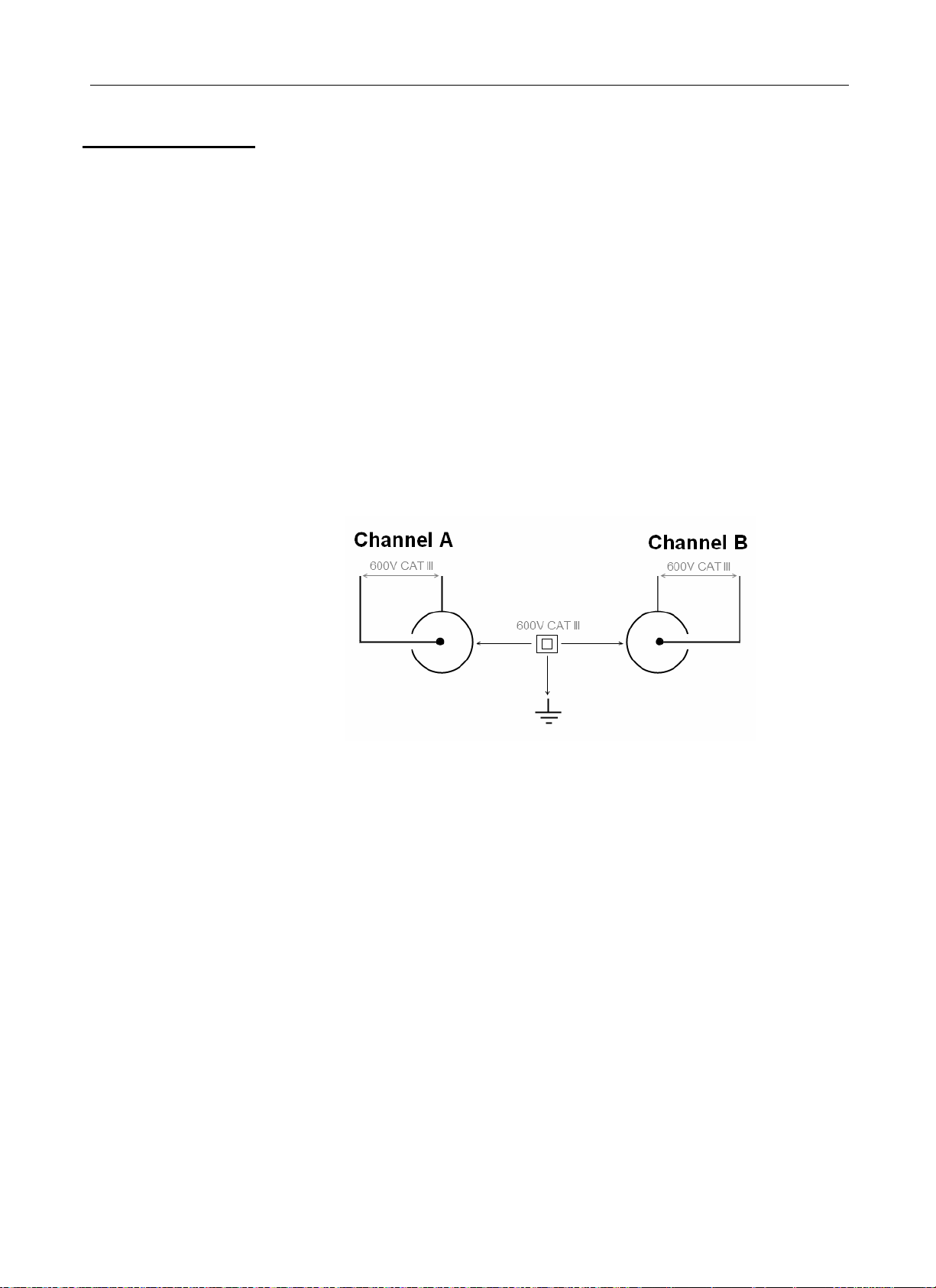
Channel insulation
The two oscilloscope input channels are insulated from each other and from
the earth and the mains power supply block. This insulation is double or
reinforced in compliance with the safety standards
IEC 61010-1 and IEC 61010-2-030.
This makes it possible to make measurements on installations or systems
connected to the electricity supply network for voltages of up to 600 V in
CAT III. The common mode authorised between the two channels is 600 V
in CAT III.
Thus the operator, the test systems and the environment are completely
protected at all times.
Any voltage (even dangerous) on one channel will not be present on the
other channel. The low points of the inputs are completely insulated, so there
is no possibility of the low points looping (which can be dangerous and highly
destructive).
The oscilloscope insulation is as shown in the diagram below:
*
The use of accessories with a voltage and/or category lower than 600 V
CAT III reduces the operating range to the lower voltages and/or
categories.
Your oscilloscope is rated 600 V CAT III; at least 600 V CAT III
accessories must be used. The accessories shipped with the instrument
allow this.
Find Quality Products Online at: sales@GlobalTestSupply.com
HandScope II - 9
www.GlobalTestSupply.com
Page 10

Description of the instrument
Description of the instrument (cont’d)
OX 5022 & OX 5042
Front panel
Back face
On / Off key
Battery charge LED
Marking
Battery cover
The removable stand makes it possible
to keep the instrument at an angle of 30 °
in relation to the horizontal.
Find Quality Products Online at: sales@GlobalTestSupply.com
II - 10 HandScope
www.GlobalTestSupply.com
Page 11

Description of the instrument
Description of the instrument (cont’d)
Measurement terminals
Marking
External
power
supply
Input
Channel "A"
Channel "B"
Input
Side
Optical
communicator
Find Quality Products Online at: sales@GlobalTestSupply.com
HandScope II - 11
www.GlobalTestSupply.com
Page 12

Description of the instrument
Description of the instrument (cont’d)
Advice for use of the sensors
Connection of the
reference
conductors to the
sensor
Distribution of stray capacitors:
It is imperative, considering the stray capacitances, to correctly connect the
reference conductors for each sensor. The conductors should preferably be
connected to the cold points to avoid the transmission of noise by the stray
capacitance between modes.
Reminder In order to prevent electric shocks or possible fires:
Reminder See p. 4 Input connection and disconnection instructions.
The noise of the digital ground (earth) is sent to the analogue input by the
stray capacitance
Never use accessories on which the casing
is accessible if it has a voltage of > 30 Vrms
compared to the earth.
This precaution is necessary for example for sensors with an
accessible metal BNC. The accessories shipped with the instrument
are compliant.
Find Quality Products Online at: sales@GlobalTestSupply.com
II - 12 HandScope
www.GlobalTestSupply.com
Page 13

Description of the instrument
Description of the instrument (cont’d)
Sensor calibration
The calibration output (3 Vpp, 1 kHz) for the sensors is underneath the
battery cover (see p. 10).
To obtain optimum response, the sensor's low frequency compensation must
be adjusted. To carry out this adjustment, the two channels of your
oscilloscope must be disconnected from the measured circuits before
opening the battery housing cover.
Select the DC coupling for the channel to which the sensor is connected and
run an autoset (icon opposite) to carry out pre-setting. Adjust the sensitivity
and the vertical offset of the channel so that the signal fills the screen, and
adjust the time base to 200 µs to view a signal period on the screen. Turn the
BNC base of the sensor in order to access the sensor adjustment screw:
Connect the sensor to be
adjusted to the calibration
output under the battery housing
cover, as shown opposite.
In the example opposite the
sensor is over-compensated:
an overshoot occurs.
Turn the screw in either direction
until the signal is horizontal and
looks like the screen shown
opposite. Your sensor is now
calibrated, so you can turn the
BNC base again to close access
to the adjustment screw.
*
Replace the battery cover in order to use your instrument in optimum safety
conditions.
Find Quality Products Online at: sales@GlobalTestSupply.com
HandScope II - 13
www.GlobalTestSupply.com
Page 14

Description of the instrument
Description of the instrument (cont’d)
Front panel
(description)
1 on / off key
3 "operating mode"
keys
5 navigation keys
The main functions of the instrument are accessed from the front panel.
The instrument is switched on by a short press on the key shown opposite. It
is switched off by a long press (a shutdown message appears and a beep
sounds).
Pressing on one of these three keys selects the instrument's operating
mode:
• "oscilloscope ", see p. 15.
• "multimeter" see p. 48.
• "harmonic analyser" see p. 57.
This block of keys is used to move around the menus and in the dialogue
boxes; it is also used to move graphic objects (cursor, trigger, memory
position...) through the menus.
• Action of the horizontal keys:
- Horizontal movement through the main menus
- Adjustment of values in the secondary menus
- Horizontal movement in a dialogue box
• Action of the vertical keys:
- Vertical movement and automatic selection in the secondary
menus
- Adjustment of values in the main menus
- Vertical movement in a dialogue box
• Action of the central "Enter" key:
- Opens a dialogue window from a main menu or a secondary
menu
- Validation of the items in a dialogue window
Find Quality Products Online at: sales@GlobalTestSupply.com
II - 14 HandScope
www.GlobalTestSupply.com
Page 15

Oscilloscope Mode - The keys
Oscilloscope Mode The keys
Pressing this key selects the "Oscilloscope" mode.
6 "Menu" keys
Trigger
Acquisition
Tools
M
easurement
Memory
Help
3 Channel A, B,
and Math or Memory keys
Channel
Channel
Function
displays the main "Trigger
displays the main "Acquisition" menu, see p. 36.
displays the main "Tools" menu, see p. 46.
displays the main "Measu
displays the main "Memory" menu, see p. 43.
displays the "Help" wind
- A simple press selects cha
- Pressing twice deselects t
- A single press selects channel M (Math
- Pressing twice deselects t
For the M (memory) channel, pressing twice invalidates the channel. Pressing
*
once again selects
reloaded.
" menu, see p. 31.
rement/Cursor" menu, see p. 40.
ow, see p. 47.
nnel A (or B) and shows the corresponding menu.
he channel.
) and shows the corresponding menu.
he channel.
the Math channel, the memory is lost and must be
2 "Time base" keys
increases the time base for acquisition up to 200 s.
decreases the time base fo
2 "sensitivity" keys
decreases the vertical sens
increases the vertical sensitivity of the last selected channel up to 200 V.
For the M channel, the "sensitivity" key varies the amplitude factor but only if
*
a math channel is validated.
2 functional keys
performs an automatic a
vertical autoset conditions the activation of the channel.
starts or stops an acquisition.
Find Quality Products Online at: sales@GlobalTestSupply.com
HandScope III - 15
www.GlobalTestSupply.com
r acquisition down to 25 ns.
itivity of the last selected channel down to 5 mV.
djustment on channels A and B. The success of each
Page 16

Oscilloscope Mode
Display
Oscilloscope Mode - Display
Display
1. Channel
data
(∗) 1.
Channel data
area
2. Area
for main
display
3. Time data
area
4. Main menu area
Battery
info. area
5.
Secondary
menu area
a) "Main channel"
area
(∗)
(∗)
Channel
identification
5 kHz filter
AC, DC, GND
coupling
Filter: no icon Æ no filter
1.5 MHz filter
Sensitivity
Unit
The direct data from channels A and B are displayed in this window:
• Channel identification
• Channel coupling
• Filter
• Channel sensitivity
• Channel unit
If no measurement is selected, if measurement is impossible or if the
channel is not validated, the measurement will be replaced
by dashes.
Find Quality Products Online at: sales@GlobalTestSupply.com
III - 16 HandScope
www.GlobalTestSupply.com
Page 17

Oscilloscope Mode - Display
Oscilloscope Mode
Display (cont’d)
b) "Automatic
measurement"
area
c ) "Math" area
or "Memory" area
Automatic
measurement
of channel A
Automatic
measurement
of channel B
Automatic
measurement
of channel A
Automatic
measurement
of channel B
The selected automatic measurements are shown in this window. 1 or 2
measurements per channel can be selected.
Channel
indicator
Automatic
measurement
Unit
Automatic
measurement 1
Violet background in "M"
Coupling
channel shows a Math
function
Filter
Sensiitivity
Green background if "M"
channel shows a Memory
The "M" channel data is shown in this window. This channel can contain a
function
"Math" or a "Memory" function.
If the "M" channel shows a "Math" function, the following data is shown:
• Channel identification
• Sensiitivity
• Unit
• Automatic measurements
If the "M" channel shows a "Memory" function, the following data is shown:
• Channel identification
• Sensitivity
• Coupling
• Filter
• Unit
• Automatic measurements
Find Quality Products Online at: sales@GlobalTestSupply.com
HandScope III - 17
www.GlobalTestSupply.com
Page 18

Oscilloscope Mode
Display (cont’d)
Oscilloscope Mode - Display
d ) "Cursor
measurement"
2. Main display
zone
Delta t
measurement
The measurements by cursor are shown in this window. The background
Delta V
measurement
Cursor 1
voltage
Cursor 2
voltage
colour is identical to that for the channel to which the cursors are attached.
It indicates:
• the horizontal difference (dt) and vertical difference (dv) between the
2 cursors,
• the voltage measurement of the cursors.
Reticle/crosshair
Horizontal trigger
position
Vertical Trigger
level indicator
Displayed
Indication of the
channel and its
vertical level
Automatic cursors
attached to
measurement 1
Cursor 1 Position
indicator for manual
measurement cursors
Selection of a
zoom zone
Cursor 2 Position indicator
for manual measurement
cursors
Find Quality Products Online at: sales@GlobalTestSupply.com
III - 18 HandScope
www.GlobalTestSupply.com
Page 19
Oscilloscope Mode - Display
Oscilloscope Mode
Display (cont’d)
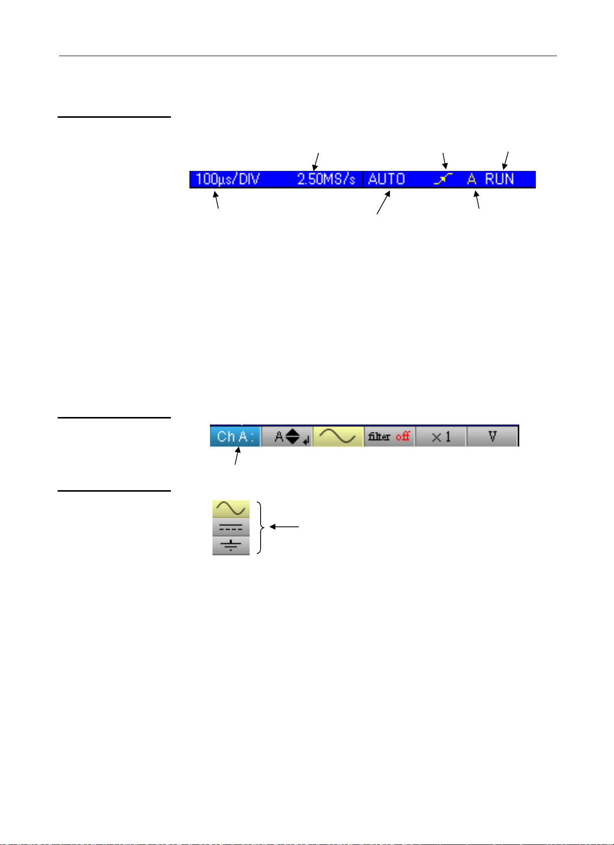
3. Time data
Sampling frequency
Time base
Triggering mode
This window is split into two groups:
• a time data group
- time base
- sampling frequency
• a trigger data group
- triggering mode
- trigger type
- trigger source
- trigger status: RUN, READY, STOP.
Trigger type
Trigger
status
Trigger
Source
4. Main menu area
5. Secondary menu
area
Main menu: displays the oscilloscope configuration
Secondary menu: gives access to various
parameter settings selected from the main menu.
Find Quality Products Online at: sales@GlobalTestSupply.com
HandScope III - 19
www.GlobalTestSupply.com
Page 20
Oscilloscope Mode
The Menus
Display
Oscilloscope Mode - The Menus
Organization
Main menu
Secondary menu
Navigation
Classical
navigation
The menus have two elements:
- a horizontal menu, called "main", located at the bottom of the screen;
- a vertical menu, called "secondary" located to the right of the screen
When a tab is selected in the menus, its background turns yellow. When a
setting is not available in the current mode, it is greyed out in the main menu
and cannot be selected.
Each tab of the main menu is associated with a secondary menu
used to view the different possible settings for the parameter in
question.
These keys are use to navigate in the main menu.
Find Quality Products Online at: sales@GlobalTestSupply.com
III - 20 HandScope
These keys are used to:
- navigate in the secondary menu,
- set a vertical parameter (see §. Vertical settings)
www.GlobalTestSupply.com
Page 21
Oscilloscope Mode - The Menus
Oscilloscope Mode
The Menus (cont’d)
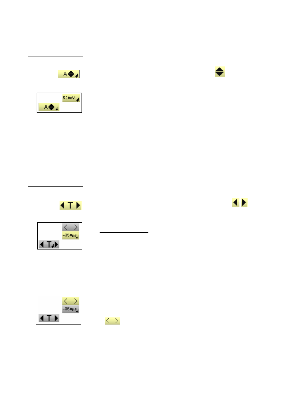
Vertical settings
Vertical settings are recognised by the double arrows on the main
menu tab.
• To change the value:
- the
value displayed in the secondary menu and therefore move the
graphic object linked to the settings in the direction of the arrows
- the
(see §. Activating a dialogue window).
keys are used to change the numeric
key opens the data entry window for direct value entry
• To quit the setting:
The
and therefore quit the setting.
Horizontal settings
The horizontal settings are recognized by the two arrows that
frame the parameter identification on the main menu tab.
keys can always be used to navigate the main menu
• To change the value: using the keys, select the
numeric value tab from the secondary menu.
- the
move the linked graphic object in the direction of the arrows;
- the
Activating a dialogue window).
• To quit the setting:
- using the
from the secondary menu;
- the
arrows are used to change the value and therefore
key is used to open the direct value entry window (see §.
keys, select the quit tab
arrows can then be used to navigate the main menu.
Find Quality Products Online at: sales@GlobalTestSupply.com
HandScope III - 21
www.GlobalTestSupply.com
Page 22
Oscilloscope mode
The Menus (cont’d)
Oscilloscope Mode - The Menus
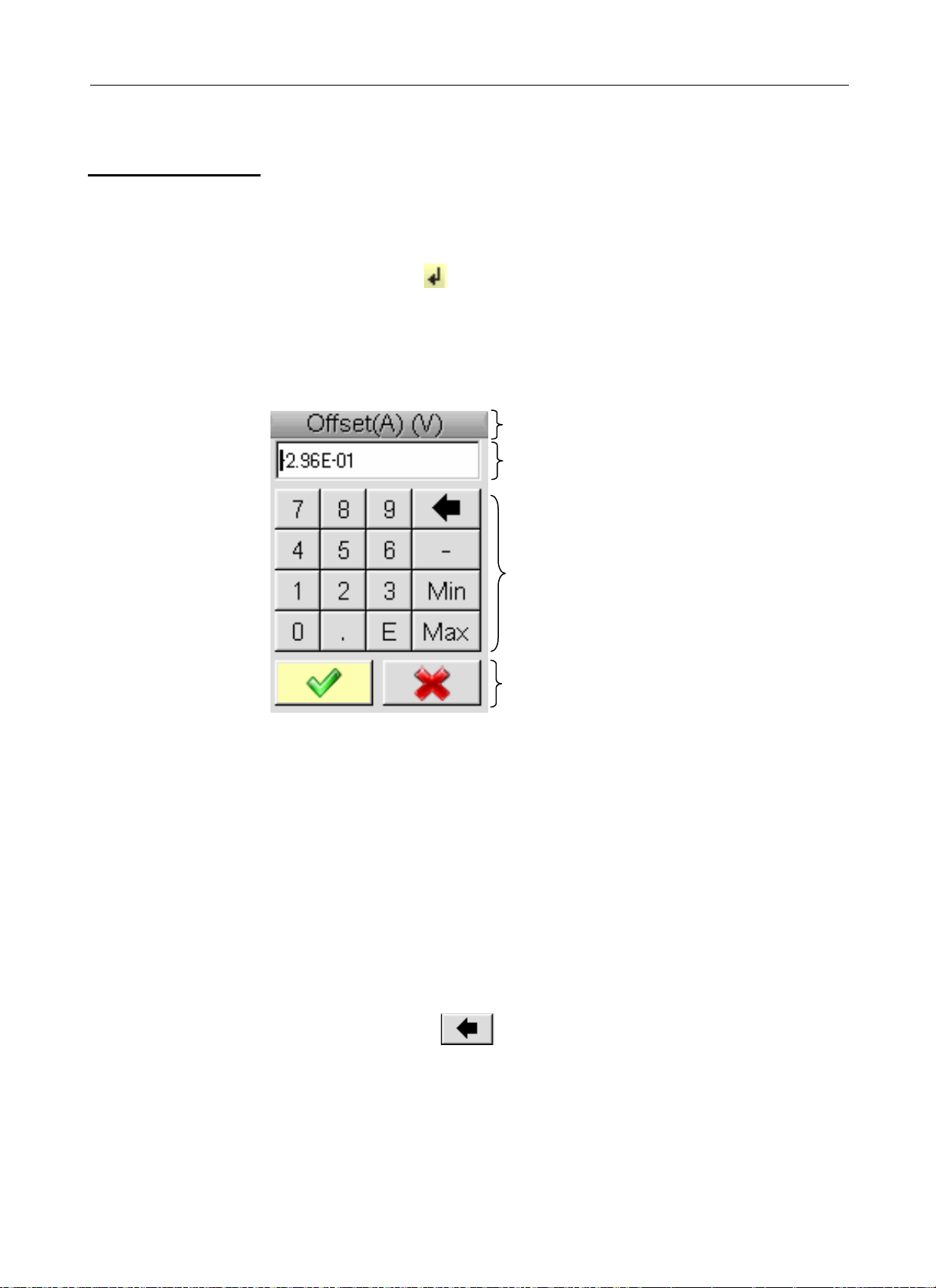
Activating
a dialogue
window
# Direct settings
entry window
The settings that can be adjusted using a dialogue window can be
recognized from the
When the tab is selected, pressing the
This window is used to directly adjust the numeric value of the parameter in
question.
symbol on the menu tab.
key opens a dialogue window.
Window title, reminder of the setting
for the channel and the unit
Display area: contains the numeric setting
value.
Numeric keypad
Validation area
Navigation in the active element window (yellow highlighting)
Validation of the activated key or, in the display area, "Input / Output" for the
selection mode.
*
The selection mode is used to select several characters from the
display area (blue highlighting) using the keys :
The selected characters can be replaced in this way by the value of the
button which is validated on the numeric keypad
(or deleted using the
When the window opens, the current variable value is completely
selected by default.
button).
Find Quality Products Online at: sales@GlobalTestSupply.com
III - 22 HandScope
www.GlobalTestSupply.com
Page 23
Oscilloscope Mode - The Channel "A" or "B" menu
Oscilloscope Mode
The Channel "A" or "B" menu
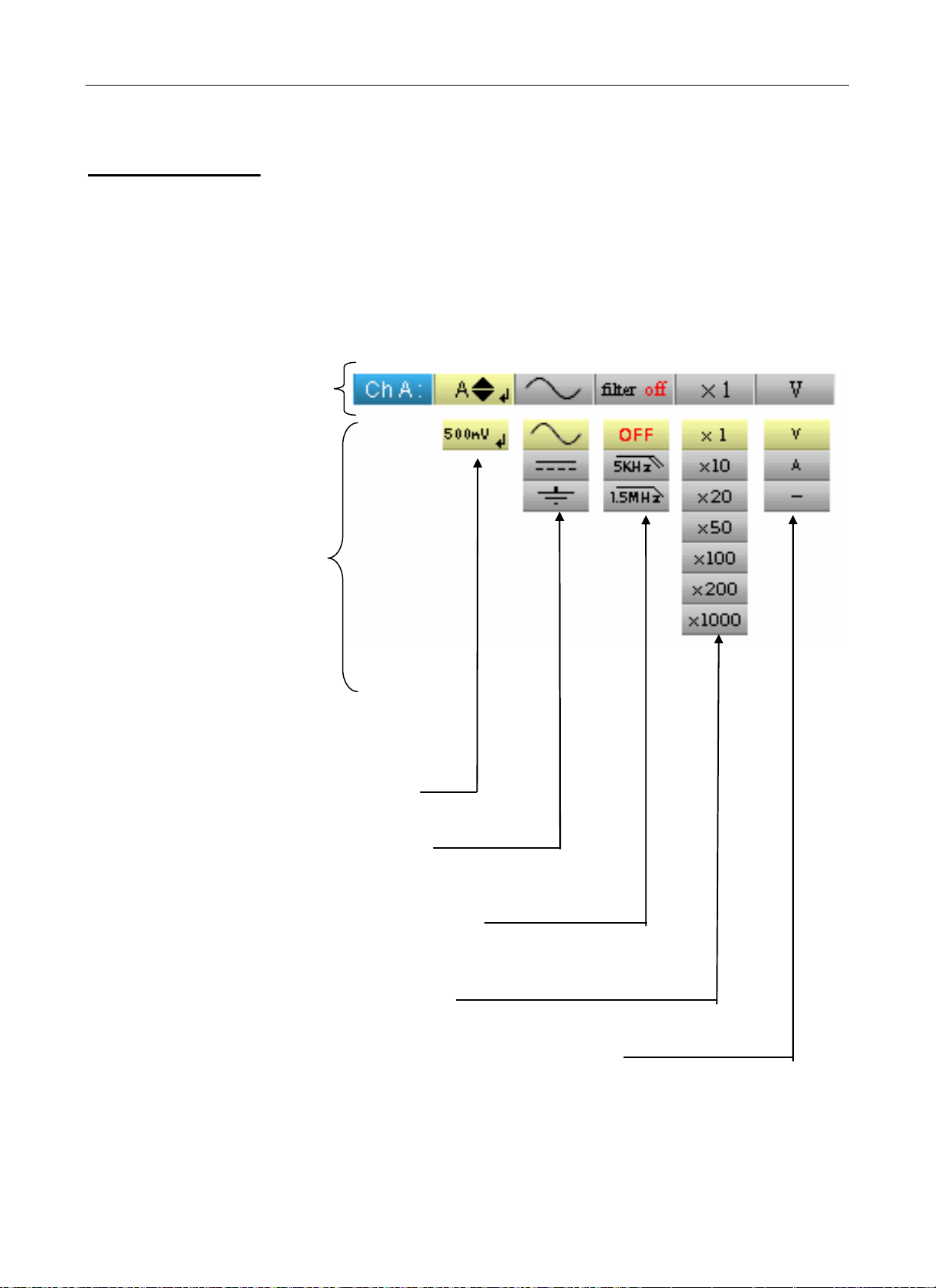
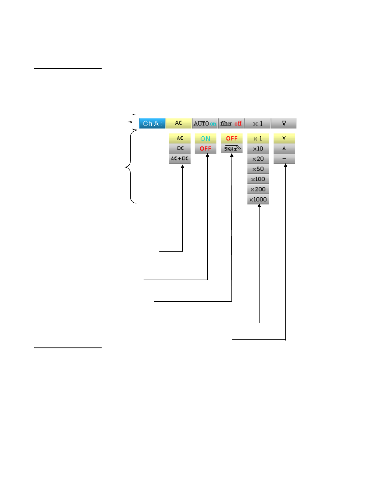
The Channel "A" or "B" menu
Press one of these two keys.
Menu
Main
menu
(∗)
• sets and displays
the numeric
value of the
vertical offset
• selects the channel coupling
(AC, DC, GND)
See example 1. p. 24.
• selects the channel filter
(OFF, 5 kHz, 1.5 MHz)
See example 2. p. 25.
• selects the sensor factor for the channel
(from x1 to x1000)
See example 3. p. 26.
• selects the channel unit (volts, amps, - )
(
-) means: no unit.
Find Quality Products Online at: sales@GlobalTestSupply.com
HandScope III - 23
www.GlobalTestSupply.com
Page 24
Oscilloscope Mode - The Channel "A" or "B" menu
Oscilloscope Mode
The Channel "A" or "B" menu (cont’d)
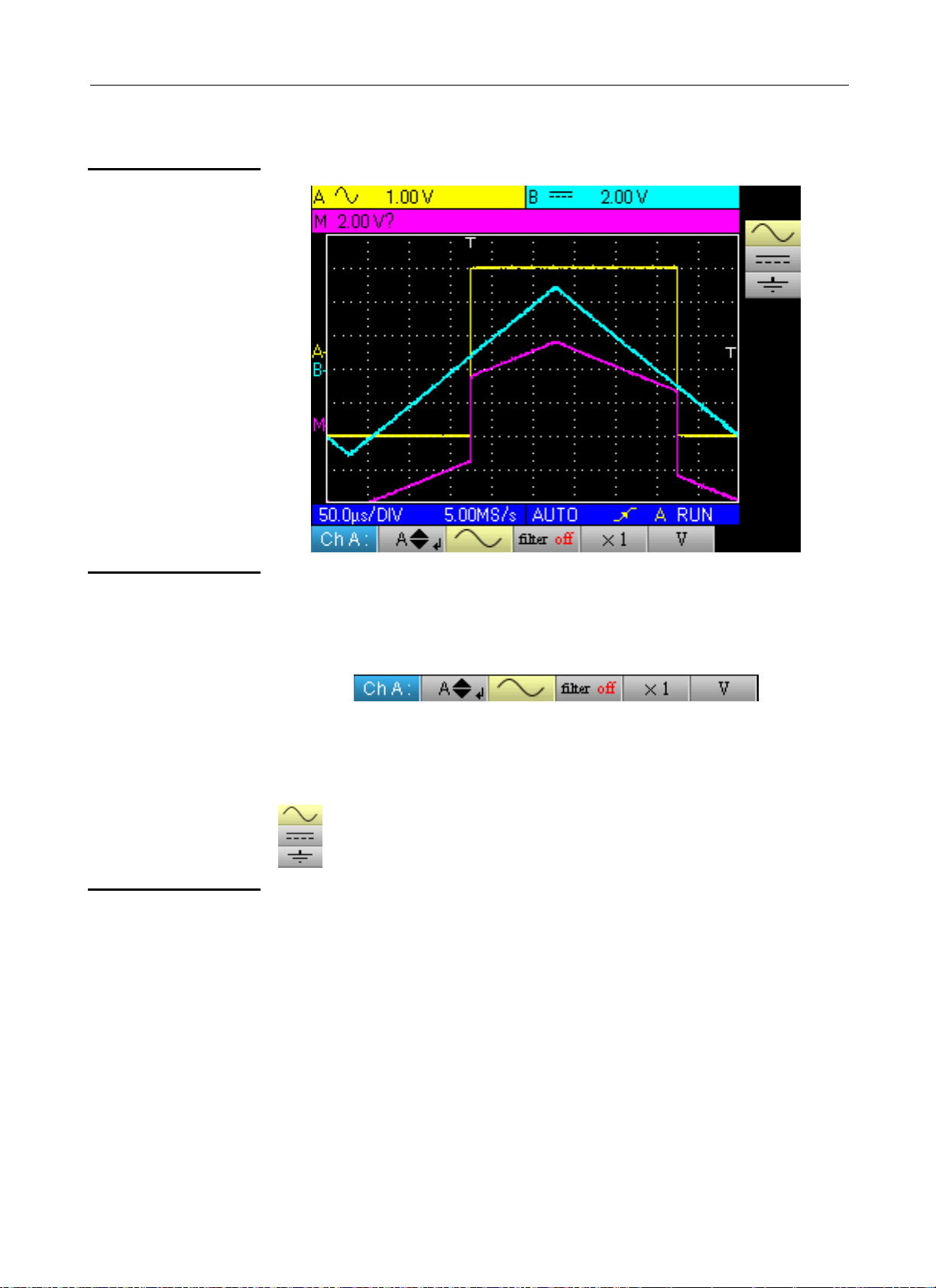
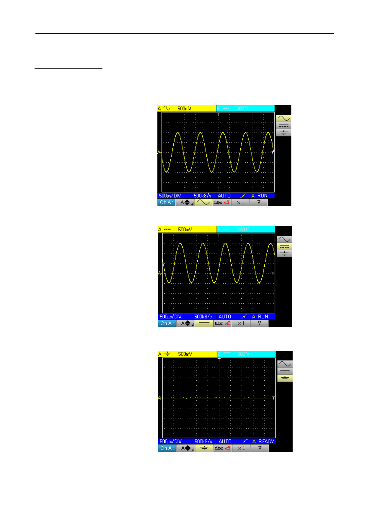
Examples
#
1. Channel
coupling
Injection of a 1kHz, 2Vpp amplitude sinusoidal signal with an offset of 0.5 V:
• with AC coupling (the DC component is removed):
• with DC coupling (the entire signal is measured):
• using GND coupling (no signals are measured):
Find Quality Products Online at: sales@GlobalTestSupply.com
III - 24 HandScope
www.GlobalTestSupply.com
Page 25
Oscilloscope Mode - The Channel "A" or "B" menu
Oscilloscope Mode
The Channel "A" or "B" menu (cont’d)
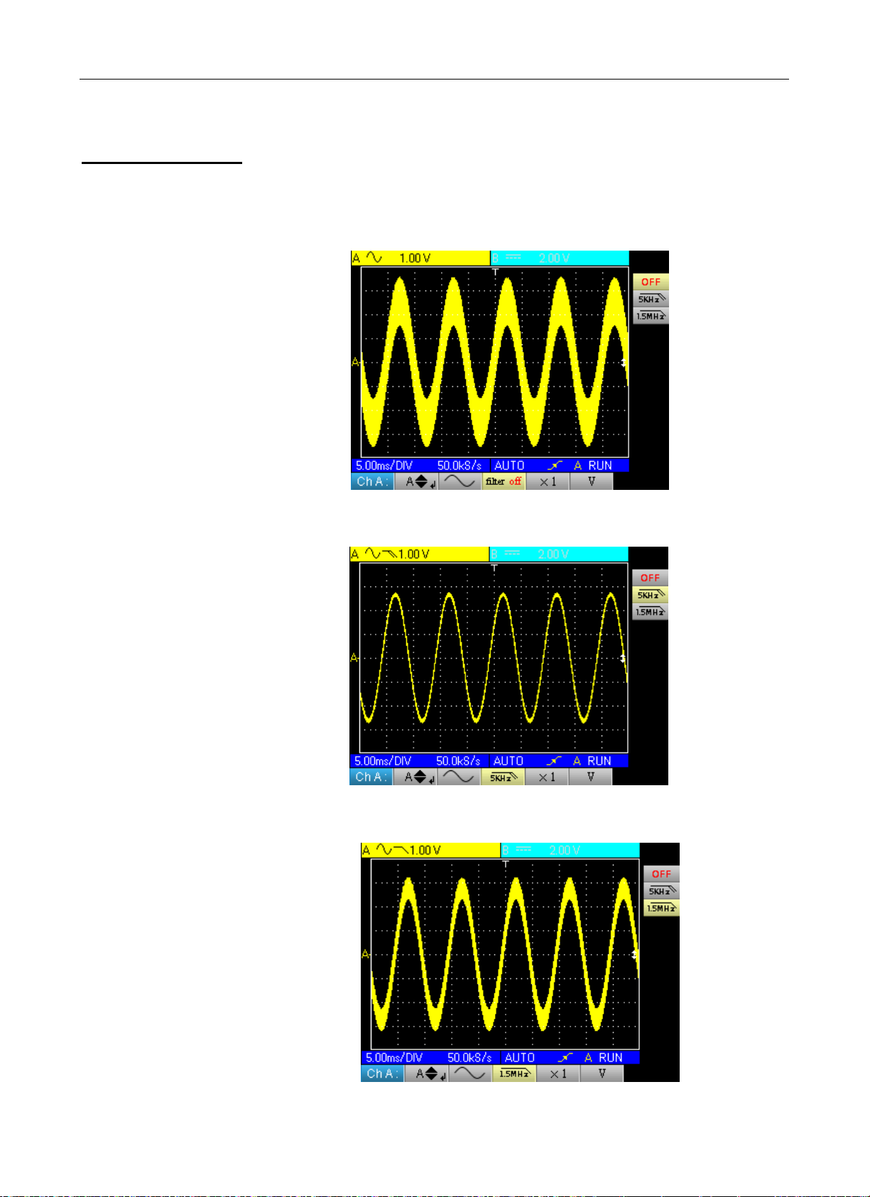
2. Channel filter
Superimposition of 2 sinusoidal signals with a frequency of 100 Hz and
3 MHz, respectively:
• without filter (both signals are sent):
• with the 5 kHz low-pass filter (the 3 MHz sinusoidal is cut):
• with the 1.5 MHz low-pass filter (the sinusoidal is partially cut):
Find Quality Products Online at: sales@GlobalTestSupply.com
HandScope III - 25
www.GlobalTestSupply.com
Page 26

Oscilloscope Mode - The Channel "A" or "B" menu
Oscilloscope Mode
The Channel "A" or "B" menu (cont’d)
3. Sensor
factor
Observation of a sinusoidal signal of 2 Vpp and 100 Hz with a x 10 sensor:
• with the factor x 1: the amplitudes and sensitivity are incorrect (factor 10)
• with the factor x 10: the amplitudes and sensitivities are correct
Find Quality Products Online at: sales@GlobalTestSupply.com
III - 26 HandScope
www.GlobalTestSupply.com
Page 27

Oscilloscope Mode - The "M Channel" menu
Oscilloscope Mode
The "Math Channel" menu
The "M Channel"
menu
Press this key.
• adjustment of the
vertical offset for the
Math channel or the
stored trace
• selects a mathematical
function
• selects the factor for the "Math"
function
Find Quality Products Online at: sales@GlobalTestSupply.com
HandScope III - 27
www.GlobalTestSupply.com
Page 28

Oscilloscope Mode
The "Math Channel" menu (cont’d)
#
Examples
Oscilloscope Mode - The "Math Channel" menu
1. Mathematical
functions
Warning, the calculation of the mathematical functions is not carried out on
physical quantities, but on the signal samples. Be careful in particular to use
identical sensitivities on channels A and B for addition and subtraction so
that the calculation is meaningful.
Thus, the sensitivity of the Math channel is determined as follows:
Operation
- A X - X
- B - Y Y
A + B X
A - B X
A * B X Y XY
A / B X Y X / Y
Sensitivity
Channel A
Sensitivity
Channel B
Y = X X
Y ≠ X
Y = X X
Y ≠ X
Sensitivity
Channel M
X ?
X ?
Example 1
M = A + B, addition of a 5 Vpp sine with a 5 Vpp square almost in phase:
Find Quality Products Online at: sales@GlobalTestSupply.com
III - 28 HandScope
www.GlobalTestSupply.com
Page 29

Oscilloscope Mode - The "M Channel" menu
Oscilloscope Mode
The "Math Channel" menu (cont’d)
In our example the amplitude of the resulting signal is 10 Vpp. As the
sensitivity of channel M is 1 Vpp, it can be seen that the trace overshoots
but is contained on the screen by dividing the representation by 2:
Example 2
M = A * B, multiplication of a 5 Vpp sine and square almost in phase:
The sensitivity of the M
channel becomes 2 V
and the amplitude
remains at 10 Vpp.
In our example, the peak
amplitude of our
mathematical function is
2.5 V * 2.5 V = 6.25 VV.
As the channel M
sensitivity is 1 VV (with
the factor x 1), it can be
seen that the trace
overshoots and can be
corrected by using the /2
coefficient.
Find Quality Products Online at: sales@GlobalTestSupply.com
HandScope III - 29
www.GlobalTestSupply.com
The sensitivity of
channel M becomes
2 VV and the peak
voltage is
3.125 * 2 VV = 6.25 VV.
Page 30

Oscilloscope Mode
The "Math Channel" menu (cont’d)
Oscilloscope Mode - The "Math Channel" menu
Example 3
M = A / B, division of a 5 Vpp sine and square almost in phase:
As the positive voltages of signals A and B are equal, the division leads to a
positive peak voltage of 1 V/V, and therefore a representation of 1 division
on the trace. This can be expanded by choosing factor x 2 or x 5:
The sensitivity of channel M changes to 500 mV/V and the positive peak
amplitude of the trace is 1 V/V.
Find Quality Products Online at: sales@GlobalTestSupply.com
III - 30 HandScope
www.GlobalTestSupply.com
Page 31

Oscilloscope Mode - The "Trigger" menu
Oscilloscope Mode
The "Trigger" menu
The "Trigger" menu
Press this key.
• selects
the Trigger
source and
the trigger
mode
• adjusts and displays
the vertical trigger
level
• sets and displays the event
time position in relation to
the trace area
used to switch
to the other menus
• selects the Trigger filter
(OFF, HF Reject, LF Reject,
Noise, Hysteresis)
See examples 1. p. 33 and 2. p. 35.
• selects the Trigger type
(front or pulse width)
• sets and displays the numeric value for "t",
a parameter of the Pulse Trigger,
this setting is only possible for the Pulse Trigger
Exit tab
Find Quality Products Online at: sales@GlobalTestSupply.com
HandScope III - 31
www.GlobalTestSupply.com
Page 32
Oscilloscope Mode
The "Trigger" menu (cont’d)
Oscilloscope Mode - The "Trigger" menu
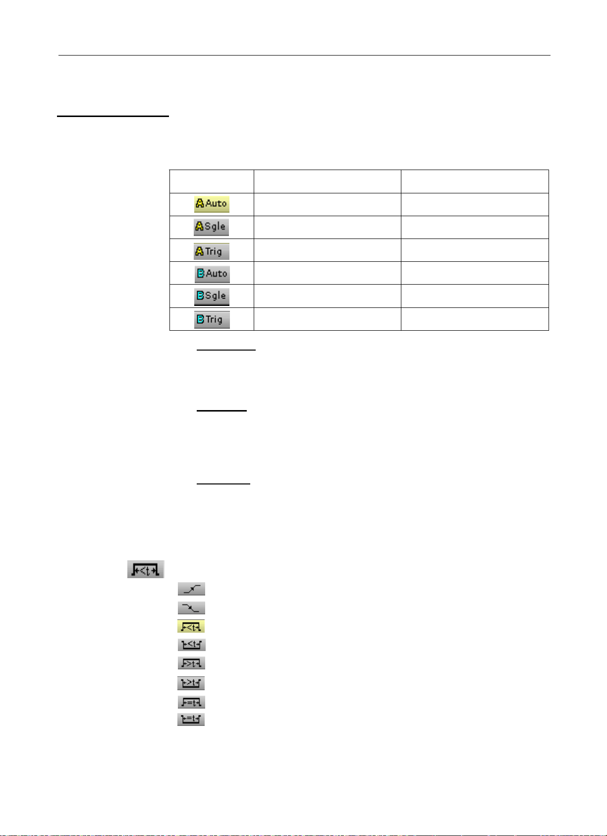
Description
Trigger Source and
trigger mode
Tab Trigger Source Triggering mode
Channel A automatic
Channel A single shot
Channel A triggered
Channel B automatic
Channel B single shot
Channel B triggered
• "Single shot" mode:
A single acquisition triggered by pressing the key opposite is authorised.
For a new acquisition the triggering circuit must be rearmed by pressing
on the key shown opposite.
• "Triggered" mode:
The content of the screen is only refreshed on a triggering event linked
to the signals present on the oscilloscope inputs.
In the absence of a triggering event related to the input signals (or the
absence of input signals), the trace is not refreshed.
• "Automatic" mode:
The content of the screen is refreshed, even if the trigger level is not
detected on the signals on the inputs.
In the presence of a triggering event, the screen refresh is managed as
in "triggered" mode.
Trigger Type
Rising edge trigger
Falling edge trigger
Pulse trigger less than "t", with positive pulse
Pulse trigger less than "t", with negative pulse
Pulse trigger greater than "t", with positive pulse
Pulse trigger greater than "t", with negative pulse
Pulse trigger equal to "t", with positive pulse
Pulse trigger equal to "t", with negative pulse
Find Quality Products Online at: sales@GlobalTestSupply.com
III - 32 HandScope
www.GlobalTestSupply.com
Page 33

Oscilloscope Mode - The "Trigger" menu
Oscilloscope Mode
The "Trigger" menu (cont’d)
Examples
#
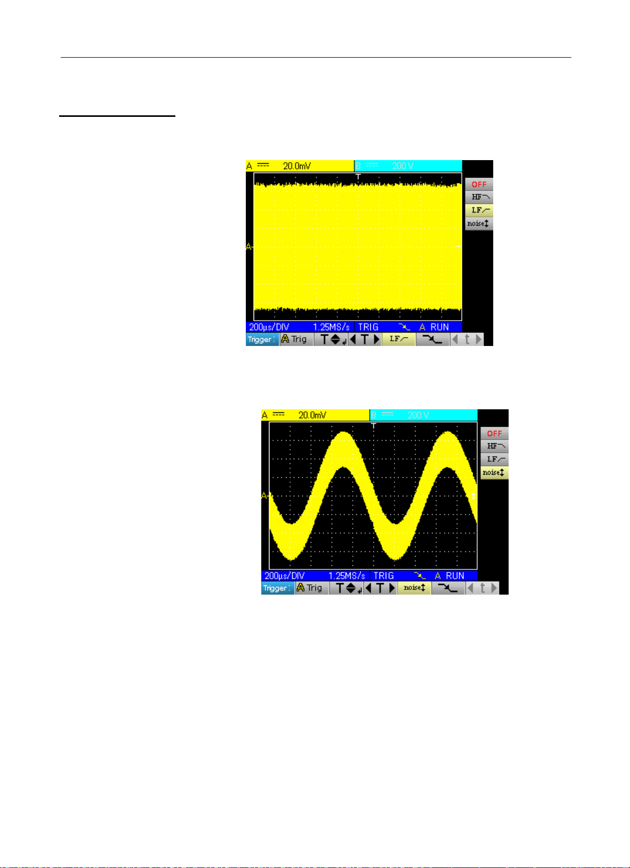
1. Trigger Filter
Display of a 1 kHz sine with noise (Acquisition Envelope ON)
• without trigger filter (we trigger on the edge of the 1 kHz signal but,
depending on the noise value, we trigger on the rising or falling edge):
• with the HF reject filter (the noise is filtered, we trigger on the 1 kHz sine:
Find Quality Products Online at: sales@GlobalTestSupply.com
HandScope III - 33
www.GlobalTestSupply.com
Page 34
Oscilloscope Mode
The "Trigger" menu (cont’d)
• with the LF reject filter (the 1 kHz signal is filtered, we trigger on the noise
Æ not effective in this case):
Oscilloscope Mode - The "Trigger" menu
• with the Noise filter (the trigger hysteresis changes to 3 div., we trigger on
the 1 kHz sine):
Find Quality Products Online at: sales@GlobalTestSupply.com
III - 34 HandScope
www.GlobalTestSupply.com
Page 35

Oscilloscope Mode - The "Trigger" menu
Oscilloscope Mode
The "Trigger" menu (cont’d)
2. Other LF reject
filter example
Observation of a slow 10 Hz sine on which peaks show every 200 ms
(PkDet activated)
• Case of noise: (we only trigger on the sine edge as it is not easy to zoom
on the peaks)
• LF reject case: (we remove the
10 Hz signal and can trigger on
the peak and zoom)
• By changing the time base, the
peaks can be observed correctly:
* This can also be achieved without a filter, but by selecting
triggering on a pulse width of less than 1µs:
Find Quality Products Online at: sales@GlobalTestSupply.com
HandScope III - 35
www.GlobalTestSupply.com
Page 36

Oscilloscope Mode
The "Acquisition" menu
Oscilloscope Mode - The "Acquisition" menu
The "Acquisition" menu
Press this key.
• activates or
deactivates the "Peak
detection" menu
See example 1, p. 37.
• selects or deactivates the
averaging function factor
See example 2, p. 38.
• activates or deactivates the
"Envelope" mode
See example 3, p. 39.
• selects the time or "XY" mode
*
In the "XY" mode, "CHA" is used as the x-
axis and "CHB" as the Y axis. The "M"
channel cannot be represented using "XY"
mode. The cursors cannot be activated in
this mode.
• selects or deactivates the "Zoom" factor
• moves the time-based zoom window (this adjustment is only
possible if a zoom is active)
Exit tab
Find Quality Products Online at: sales@GlobalTestSupply.com
III - 36 HandScope
www.GlobalTestSupply.com
Page 37

Oscilloscope Mode - The "Acquisition" menu
Oscilloscope Mode
The "Acquisition" menu (cont’d)
Examples
#
1. PkDet
acquisition
Observation of rapid pulse combs with a low repetition frequency
• without PkDet (the repetition frequency of the combs gives an
inappropriate sampling frequency for viewing the signal, so there are
missing combs):
• with PkDet (the detection of the min and max obtained between two
sampling steps makes it possible to view all the combs):
Find Quality Products Online at: sales@GlobalTestSupply.com
HandScope III - 37
www.GlobalTestSupply.com
Page 38
Oscilloscope Mode
The "Acquisition" menu (cont’d)
Oscilloscope Mode - The "Acquisition" menu
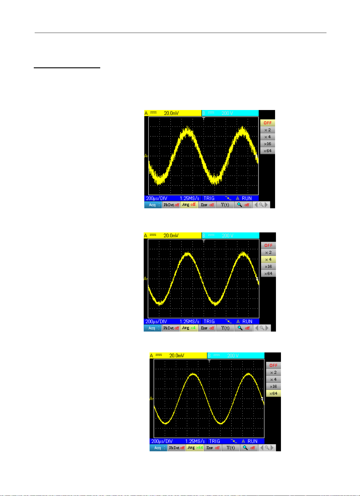
2. Acquisition
averaging
Observation of a 1 kHz sine with noise. Prior to averaging make sure that
the trace is stable. In our example the Noise filter from the Trigger menu is
activated.
• without averaging:
• with x 4 averaging (the noise is reduced):
• with x 64 averaging (the noise has almost disappeared):
Find Quality Products Online at: sales@GlobalTestSupply.com
III - 38 HandScope
www.GlobalTestSupply.com
Page 39

Oscilloscope Mode - The "Acquisition" menu
Oscilloscope Mode
The "Acquisition" menu (cont’d)
3. Envelope
acquisition
Observation of a sinusoidal signal with amplitude modulation
• without envelope (an acquisition is viewed at each triggering):
• with Env (the acquisitions are cumulated and an envelope is made using
the min and max points for each x axis):
Find Quality Products Online at: sales@GlobalTestSupply.com
HandScope III - 39
www.GlobalTestSupply.com
Page 40
Oscilloscope Mode
The "Measurement" menu
Oscilloscope Mode - The "Measurement" menu
The "Measurement" menu
Press this key.
• activates or
deactivates
automatic
measurement
display
• used to open the
configuration window
for automatic
measurements on the
channel in question
(by pressing the key
opposite) (∗)
• activates or deactivates cursor
measurements
• sets and displays the numeric value of
cursor 1 position(∗∗)
• sets and displays the numeric value of
cursor 2 position (∗∗)
(∗) This setting is only possible if the automatic
measurement display is active.
(∗∗) This setting is only possible if the cursors are active.
Find Quality Products Online at: sales@GlobalTestSupply.com
III - 40 HandScope
www.GlobalTestSupply.com
Page 41

Oscilloscope Mode - The "Measurement" menu
Oscilloscope Mode
The "Measurement" menu (cont’d)
Description
of the configuration
window
for automatic
measurements
Name Measurement description Automatic cursor indication
Vmin
Vmax
Vpp
Vlow
Vhigh
Vamp
Vrms
Vavg
Over+
Trise
Tfall
W+
W-
P
F
DC
Pulses
OverPhase (A)
Phase (B)
minimum peak voltage Vavg and Vmin
maximum peak voltage Vavg and Vmax
peak-to-peak voltage Vmin and Vmax
established low voltage Vavg and Vlow
established high voltage Vavg and Vhigh
amplitude Vlow and Vhigh
root-mean-square voltage Vrms and measurement interval
average voltage Vavg and measurement interval
positive offset Vmin and Vmax
rise time points used for the calculation
fall time points used for the calculation
width of positive pulse (at 50% Vamp) Vavg and points used for the calculation
width of negative pulse (at 50% Vamp) Vavg and points used for the calculation
period Vavg and points used for the calculation
frequency Vavg and points used for the calculation
duty cycle Vavg and points used for the calculation
number of pulses Vavg and points used for the calculation
negative overshoot Vmin and Vmax
reference channel B, "channel A
phase shift"
reference channel A, "channel B
phase shift"
Movement of the selection in the window
Validation of the selection
Vavg and period used for the calculation
Vavg and period used for the calculation
*
1 or 2 automatic measurements per channel can be selected. The
automatic cursors are assigned to the last selected measurement
which is displayed in the first position on the screen. When the
measurement is possible, the automatic cursors provide an additional
indication, see the table above.
Find Quality Products Online at: sales@GlobalTestSupply.com
HandScope III - 41
www.GlobalTestSupply.com
Page 42

Oscilloscope Mode
y
The "Measurement" menu (cont’d)
Measurement
conditions
• The measurements are made on the entire depth of the acquisition.
• Any modification of the signal causes an update of the measurements.
These are refreshed at the same rhythm as the acquisition.
• The accuracy of the measurements is optimal if two complete periods
of the signal are displayed.
Oscilloscope Mode - The "Measurement" menu
Presentation
of automatic
measurements
100%
90%
50%
10%
0%
Vavg
L
T = 1/F
W+ W-
>5%T
Trise
tm
Tfall
td
>5%T
• Positive overshoot = [100 * (Vmax – Vhigh)] / Vamp
• Negative overshoot = [100 * (Vmax – Vlow)] / Vamp
=
ni
• Vrms =
• Vavg =
1
∑
n
=
1
∑
n
=
−
GND
i
=
0i
ni
−
GND
i
0i
1/22
])y(y[
)y(y
Vmax
igh
Vh
avg
Vamp Vpp
Vlow
Vmin
Y
= value of the point representing zero Volts
GND
Phase
measurement
Automatic measurement of one trace's phase compared with the other
trace.
No phase measurements are possible on the M channel.
The choice of the measurement configuration window (channel A or B) on
which the phase measurement is selected conditions the reference
channel for the phase-shift measurement.
If the selection is made from the channel A window: channel B becomes
the reference channel and the oscilloscope displays the phase shift of
channel A in relation to channel B.
Find Quality Products Online at: sales@GlobalTestSupply.com
III - 42 HandScope
www.GlobalTestSupply.com
Page 43

Oscilloscope Mode - The "Memory" menu
Oscilloscope Mode
The "Memory" menu
The "Memory" menu
Press this key.
.
• activates/deactivates
the reference display
See example, p. 44.
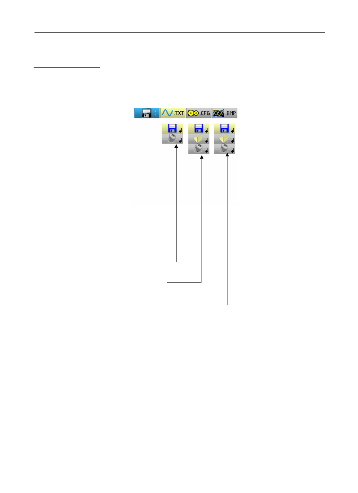
• manages stored traces (.trc)
Definition of the
common icons
• manages stored traces (.txt)
* The .txt traces cannot be
reloaded on the HandScope but
can be used in Spreadsheet software.
• manages memorised configurations (.cfg)
*
The .cfg files are specific to the
HandScope and are not compatible with
the brand's other instruments.
• manages memorised screenshots (.bmp)
gives access to the window for recording a trace, a text trace or a
stored configuration or screenshot.
gives access to the trace, configuration or screenshot recall window.
gives access to the window for deleting a trace, configuration, text
trace, stored configuration or screenshot.
The file name is generated automatically (# e.g. trace_01.txt, etc.)
Find Quality Products Online at: sales@GlobalTestSupply.com
HandScope III - 43
www.GlobalTestSupply.com
Page 44

Oscilloscope Mode
The "Memory" menu (cont’d)
Oscilloscope Mode - The "Memory" menu
Storage capacity
The memory's capacity is 2 MB (500 kb of which used by File System) and it
can be used to store traces, screenshots, configurations and measurement
files (p. 66).
The file names are generated automatically by incrementingthe file index from
00 to 99 (# e.g.: trace-00.TX
10.BMP, meter-20.TXT …).
When the memory is full the message "Error: Memory Full!" appears.
There are 3 possible solutions:
T, trace-01.TRC, setup-03.CFG, screen-
• delete the files one by one using the "Memory" option (Æ data is lost).
• transfer the files to a PC via SX-METRO or remote commands (see
programming instructions).
• completely reinitialise the memory
ª Warning! All files will be lost.
1. Turn off the instrument and press and .
2. While keeping the keys pressed down, press on and wait
for the symbol opposite to appear.
3. The deletion takes about forty seconds.
# Example
Trace
reference
Observation of a sinusoidal signal with amplitude modulation
The reference signal appears in light yellow. The amplitude signal is no
longer the same as the reference.
A reference memory is volatile; it is lost when the instrument is powered off, or
when the channel or reference is deactivated.
Find Quality Products Online at: sales@GlobalTestSupply.com
III - 44 HandScope
www.GlobalTestSupply.com
Page 45

Oscilloscope Mode - The "Memory" menu
Oscilloscope Mode
The "Memory" menu (cont’d)
Description
Recording
management
• of a .trc trace
• of a .txt trace
•
configuration
• of a .bmp
screenshot
management
• of a .trc trace
of a .cfg
Recall
# Example:
Text zone
indicating the
name under
which the file
will be saved to
the user.
Trace selection
zone. The user
chooses the
trace to be
saved.
# Example:
Confirm or
Cancel buttons
Confirmation of
elements
•of a .cfg
configuration
• of a .bmp
screenshot
*
Deletion
management
• of a .trc trace
• of a .txt trace
of a .cfg
•
configuration
of a .bmp
•
screenshot
List of .cfg
files
Confirm or
Cancel
buttons
• A recalled .trc trace will be displayed on the M channel with a
green background.
• A factory configuration called 'default.cfg' is used to return to the
original factory settings.
# Example:
List of .txt
files
Confirm or
Cancel
buttons
Find Quality Products Online at: sales@GlobalTestSupply.com
HandScope III - 45
www.GlobalTestSupply.com
Page 46

Oscilloscope Mode
The "Tools" menu
Oscilloscope Mode - The "Tools" menu
The "Tools" menu
Press this key. This menu is the same in "Multimeter" and "Harmonic
analyser" modes.
• selects the language:
• opens the "RS/USB Information" window:
This windows gives
information about
• opens the "About..." window:
- the instrument name, the software / hardware version and the serial
number
- the startup and acquisition programme versions
- the website to visit to obtain news on the METRIX instrument range,
- the customer support E-mail address to obtain answers to your questions
concerning the instrument.
Find Quality Products Online at: sales@GlobalTestSupply.com
IV - 46 HandScope
www.GlobalTestSupply.com
Page 47

Oscilloscope Mode - The "Help" key
Oscilloscope Mode
The "Help" key
The "Help" key
# Example
Press this key to activate / deactivate the integrated help function.
In all modes it displays a help window for the current menu.
Main title of the current help
A Pointer placed
opposite the tab
of the secondary
menu for which
help is needed.
Pointer placed
opposite the tab of
the main menu.
Scroll bar; its position
can be changed by
using the vertical
sensitivity keys:
Find Quality Products Online at: sales@GlobalTestSupply.com
HandScope III - 47
www.GlobalTestSupply.com
Page 48

Multimeter Mode
The keys
Multimeter Mode - The keys
6 "Menu" keys
Trigger
Acquisition
Tools
M
easurement
Mem
ory
Help
3 keys
Channel A, B and
Math
Channel
pressing this key selects the "Multimet
digital multimeters are available.
inactive in "Multimeter" mode.
inactive in "Multimeter" mode.
displays the main "Tools" menu, identical to the Oscilloscope mode, see p. 15.
displays the main "Measurement/Cursor" menu, see p. 40.
displays the main "Memory" menu, see p. 43.
displays the "Help" window, identical to the Oscillo
- A single press selects channel "A" (or
menu.
- Pressing twice deselects the channe
er" mode; 2 independent 8,000-count
scope mode, see p. 47.
"B") and shows the corresponding
l.
Channel
Function
2 "Time base" keys
2 "Sensitivity" keys
2 functional keys
inactive in "Multimeter" mode.
increases the recording time in the viewing wind
decreases the recording time in the viewing win
decreases the range of the last selected channel.
increases the range of the last
inactive in "Multimeter" mode.
selected channel.
ow.
dow.
The RUN/HOLD key activates
Find Quality Products Online at: sales@GlobalTestSupply.com
IV - 48 HandScope
www.GlobalTestSupply.com
or deactivates the Hold mode.
Page 49
Multimeter Mode - Display
Multimeter Mode
Display
Display
1. Measurement zone
(∗) 1.
Measurement
zone
2. Graphic
window
area
If the measurement is not possible, dotted lines will be displayed. If the
(∗)
channel is not validated the measurement will be replaced by "-x-".
3. Main menu area
Channel
indicator
Battery info. area
Measurement
type
4.
Secondary
menu area
Main
measurement
The direct data from channels A and B are displayed in this window:
Secondary
measurement 1
Secondary
measurement 2
Secondary
measurement 3
• Channel indicator
• Coupling
• Filter
• Measurement type
• Main measurement
• Secondary measurement 1
• Secondary measurement 2
• Secondary measurement 3
Find Quality Products Online at: sales@GlobalTestSupply.com
HandScope IV - 49
www.GlobalTestSupply.com
Page 50
Multimeter Mode - Display
Multimeter Mode
Display (cont’d)
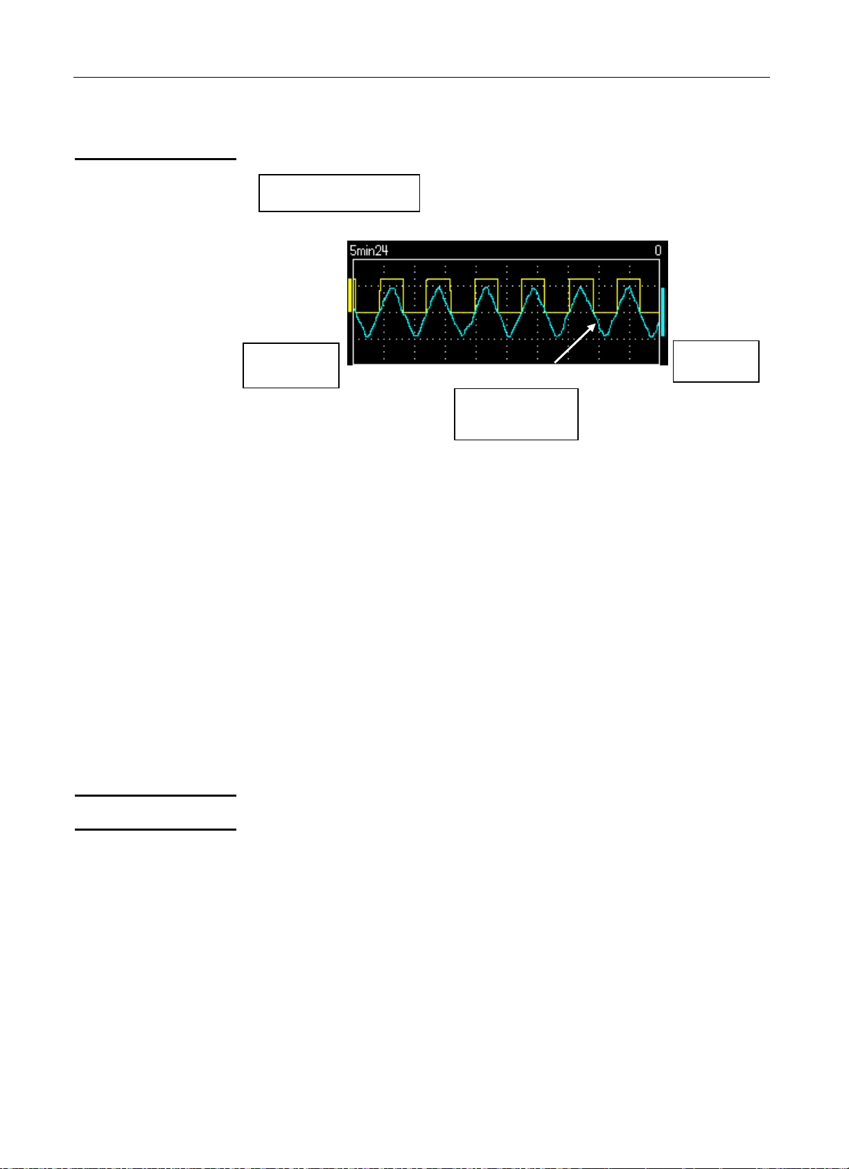
2. Graphic window area
Depth of the
display window
Channel A
bargraph
Curves of
channel
A and B
This window shows the measurement changes as a function of time, i.e.:
Channel B
bargraph
• the trend curves for the main measurement on each channel
• the reticle
• the operation duration
• a bargraph per channel
Trend curve
Observation
duration
Bargraph
3. Main menu area
4. Secondary menu area
The trend curve is displayed over 270 points.
The depth of the window represents the observation duration:
2700 measurements are used.
Possible settings: 5’24’’, 15’, 30’, 1hr, 6hrs, 12hrs, 24hrs, 1 week, 1 month.
These bargraphs show the min and max measured values.
* A range change reinitialises the bar graph at deletes the
measurement trend curve.
Find Quality Products Online at: sales@GlobalTestSupply.com
IV - 50 HandScope
www.GlobalTestSupply.com
Page 51
Multimeter Mode - The "Measurement" menu
Multimeter Mode
The "Measurement" menu
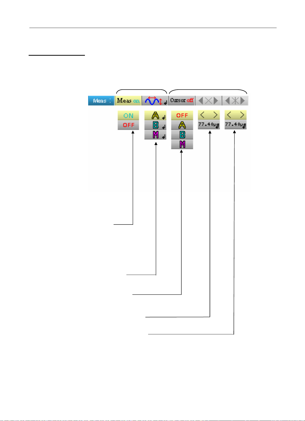
The "Measurement" menu
Press this key.
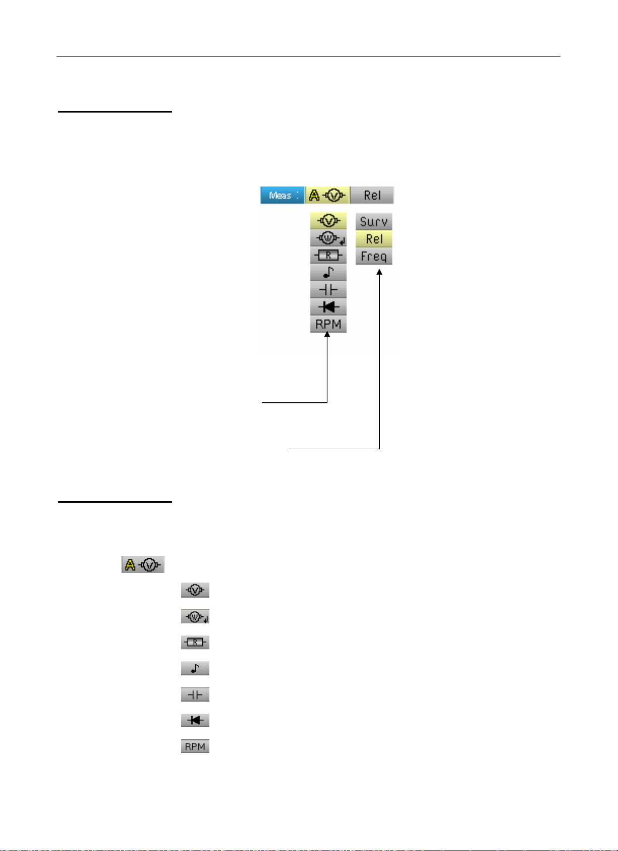
Description
Channel "A" main
measurement
• selects the main
measurement on
channel A
• selects the secondary
measurement displayed
on the channels
* Channel "B" is assigned to voltage measurement, when
possible.
Amplitude measurement
Active power measurement
Ohmmeter
Find Quality Products Online at: sales@GlobalTestSupply.com
HandScope IV - 51
Continuity
Capacitance meter
Component test
Rotation speed measurement (specific sensor)
www.GlobalTestSupply.com
Page 52

g
Multimeter mode
The "Measurement" menu (cont’d)
Multimeter Mode - The "Measurement" menu
Power
measurement and
dialogue
window for
"measurement
selection"
Display of the
power
measurement and
forced tabs
# Example
When selecting
displays the window below. You can thus choose the measurement type:
active power measurement, pressing on "Enter"
• Single-phase
• Balanced three-phase without N
• Balanced three-phase with N
The power measurement imposes the following settings:
- Channel A unit: V (volt)
- Channel B unit: A (amps)
- Channel A and B coupling: AC
By default the power covers the measurement of channel A; pressing the
key is used to view the measurement of channel A, the power then
covers the measurement of channel B and vice versa with the
Measurement of power
coverin
channel A
Press the key:
Secondary
measurements
Channel A measurement
Channel B measurement
key.
Secondary
measurements
Measurement of
power covering
channel B
Find Quality Products Online at: sales@GlobalTestSupply.com
IV - 52 HandScope
www.GlobalTestSupply.com
Page 53

Multimeter Mode - The "Measurement" menu
Multimeter Mode
The "Measurement" menu (cont’d)
Secondary
measurement
selects the secondary measurement displayed on the channels:
*
)
activates the secondary monitoring measurement. This comprises
three measurements:
• min Æ the minimum measured value
• max Æ the maximum measured value
• avg Æ the average value since the last reset
activates the relative secondary measurement. This comprises three
measurements:
• rel Æ the difference between actual value and reference value
• ref Æ the reference value
• Δ Æ the difference in %
activates the secondary frequency measurement.
The choice of secondary measurement is applied to all channels.
The secondary measurement validated by default is frequency.
You can reset the secondary monitoring or relative measurements by:
- pressing
measurement choice menu,
when the active main menu is the secondary
- by temporarily changing the secondary measurement,
- by deactivating and reactivating the channel,
- by changing the range.
Find Quality Products Online at: sales@GlobalTestSupply.com
HandScope IV - 53
www.GlobalTestSupply.com
Page 54
Multimeter Mode
The Channel "A" or "B" menu
Multimeter Mode - The Channel "A" or "B" menu
The Channel "A" or "B" menu
Press one of these two keys.
Main
Menu
Main
menu
(1)
• selects the channel
coupling
(AC, DC, GND)
See example p. 24.
Notes
(2)
• activates or deactivates
autorange
(1)
• selects the channel filter
(OFF, 5 kHz)
(1)
• selects the channel sensor factor
(x 1 to x 1000)
(1)
• selects the channel unit (Volt, Amps, - )
These tabs are not accessible if the following types of measurement are
(1)
validated:
• Capacitance meter
• Ohmmeter
• Component test
• Continuity
• RPM
(2)
These tabs are not accessible if the following types of measurement are
validated:
• Component test
• Continuity
• RPM
Find Quality Products Online at: sales@GlobalTestSupply.com
IV - 54 HandScope
www.GlobalTestSupply.com
Page 55

Multimeter Mode - The Channel "A" or "B" menu
Multimeter Mode
The Channel "A" or "B" menu (cont’d)
#
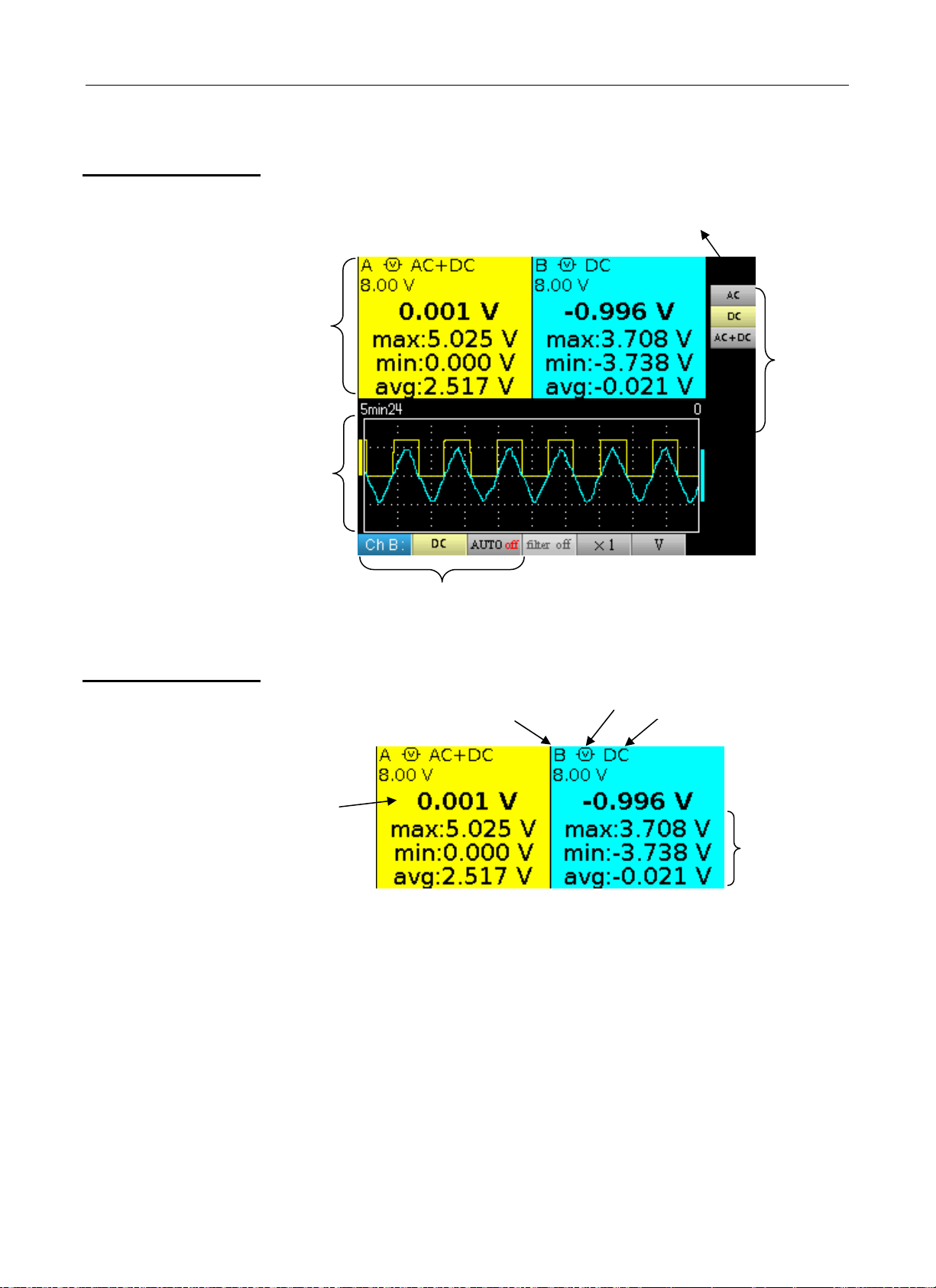
Example
Multimeter
coupling
In voltmeter mode, 3 types of coupling are possible:
• AC is used to measure the VAC RMS voltage of the signal without its
DC component,
• DC is used to measure the signal's VDC voltage,
• AC + DC gives the VAC + DC RMS voltage of the entire signal.
where:
Find Quality Products Online at: sales@GlobalTestSupply.com
HandScope IV - 55
www.GlobalTestSupply.com
Page 56
Multimeter Mode
The "Memory" menu
Multimeter Mode - The "Memory" menu
The "Memory" menu
This menu operates in exactly the same way as in the "Oscilloscope" mode.
Press this key.
• selects saved
trace management
(.txt)
• selects saved configuration
management (.cfg)
• selects saved screenshot management
(.bmp)
Find Quality Products Online at: sales@GlobalTestSupply.com
IV - 56 HandScope
www.GlobalTestSupply.com
Page 57

"Harmonic Analyser" Mode - The Keys
Harmonic Analyser Mode
The Keys
6 "Menu" keys
Trigger
Acquisition
Tools
M
easurement
Memory
Help
3 ke
ys
Channel “A” + “B”
and Math
Channel
Pressing this key selects the "Harmonic Analy
inactive in "Harmonic Analy
displays the main "Acquisition" menu, see p. 36.
displays the main "Tools" menu, id. to the Oscilloscope mode, see p. 46.
inactive in "Harmonic Analy
displays the main "Memory" menu,
displays the "Help" window, identical to the Oscilloscope mode, see p. 47.
- A single press selects channel A (or B) and shows the corresponding
menu.
- Pressing
twice deselect
ser" mode.
ser" mode.
s
the channel.
see p. 43.
ser" mode.
Channel
Function
2 "Time base" keys
2 "Sensitivity" keys
2 functional keys
inactive in "Harmonic Analy
inactive in "Harmonic Analyser" mode.
inactive in "Harmonic Analyser" mode.
same as "Oscilloscope " mode, see p. 15.
same as "Oscilloscope " mode, see p. 15.
same as "Oscilloscope " mode, see p. 15.
same as "Oscilloscope " mode, see p. 15.
ser" mode.
Find Quality Products Online at: sales@GlobalTestSupply.com
HandScope V - 57
www.GlobalTestSupply.com
Page 58

Harmonic Analyser Mode - Display
Harmonic Analyser Mode
Display
Visualisation
(∗) 1. Measurement
area
2. Graphic
window
area
3. Harmonic
reference
area
The indication using a double black
line on the harmonics corresponds to
the representation of overshooting
harmonics.
Battery
info. area
5. Secondary
menu area
1. Measurement
zone
4. Main menu area
(∗)
If no measurement is selected, or if the channel is not validated, the
measurement will be replaced by dots.
Channel
indicator
Filter
RMS
Coupling
Sensitivity
This window displays two measurements and contains data on the
channels:
• Channel indicator
• Coupling
• Filter
• RMS voltage of the signal in V
• Total Harmonic Distortion (THD) in %
HDR
Find Quality Products Online at: sales@GlobalTestSupply.com
V - 58 HandScope
www.GlobalTestSupply.com
Page 59

Harmonic Analyser Mode - Display
Harmonic Analyser Mode
Display (cont’d)
2. Harmonic
display area
Channel A harmonic,
same colour
as the
Vertical scale
in percentage of the
fundamental
Horizontal scale,
harmonic
numbering
Overshooting
harmonics
channel
Channel B harmonic,
same colour as the
channel
3. Harmonic
reference area
This area displays harmonics 1 to 16 of the validated channels in the form
of a bar char
t. The user can switch from the display of harmonics 2 to 16 to
the display of harmonics 17 to 31. The max. vertical scale will depend on
the zoom factor. The zoom factor can be modified using the Acq menu.
Harmonic
selection
pointer
Phase in degrees in
relation to the
fundamental
Number of the selected
harmonic
Value in
percentage of
the highest
amplitude
harmonic
Frequency
RMS value
Channel A
data area
Channel B
data area
This window displays the specific measurements of the selected harmonic
for each cha
The followin
nnel.
g measurements are displayed:
• the value in % of the highest amplitude harmonic
• the phase in degrees in relation to the fundamental
• the frequency in Hz
• the RMS voltage in V
The title of the group corresponds to the selected harmonic.
A different background colour will differentiate between channel A and
channel B measurements.
4. and 5. Main
and secondary
menu areas
Find Quality Products Online at: sales@GlobalTestSupply.com
HandScope V - 59
www.GlobalTestSupply.com
Page 60

Harmonic Analyser Mode
The Channel "A" or "B" menu
Harmonic Analyser Mode - The Channel "A" or "B" menu
The Channel "A" or "B" menu
Main
menu
Secondary
menus
This menu operates in exactly the same way as in the "Oscilloscope" mode.
Press one of these two keys.
displays the
numeric offset
value
selects the
channel coupling
(AC, DC, GND)
selects the channel filter
(OFF, 5 kHz, 1.5 MHz)
selects the channel factor
(from x1 to x1000)
selects the channel unit (Volt, Amps, - )
Find Quality Products Online at: sales@GlobalTestSupply.com
V - 60 HandScope
www.GlobalTestSupply.com
Page 61

Harmonic Analyser Mode - "Acquisition" menu
Harmonic Analyser Mode
The "Acquisition" menu
The "Acquisition" menu
Press this key.
• adjusts and displays the number
of the selected harmonic
Exit tab
• Averaging
Identical to "Oscilloscope" mode
• selects the vertical zoom factor
100 % of the fundamental
50 % of the fundamental
25 % of the fundamental
10 % of the fundamental
The user can change the vertical scale of the harmonics display area so
that it is easier to view the harmonics with low amplitude compared with
the fundamental.
Find Quality Products Online at: sales@GlobalTestSupply.com
HandScope V - 61
www.GlobalTestSupply.com
Page 62

Harmonic Analyser Mode
The "Memory" menu
Harmonic Analyser Mode - "Memory" menu
The "Memory" menu
This menu operates in exactly the same way as in the "Oscilloscope" mode.
Press this key.
• manages stored
configurations (.cfg)
• manages stored
screenshots (.bmp)
Find Quality Products Online at: sales@GlobalTestSupply.com
V - 62 HandScope
www.GlobalTestSupply.com
Page 63

Remote programming
Remote programming
Presentation
Connecting the oscilloscope
The oscilloscope can be programmed remotely from a computer:
• either using the SX-METRO software,
• or using basic standardised commands that comply with the
IEEE488.2 standard and the SCPI protocol.
This remote programming is used to:
• Configure the instrument
• Perform measurements and retrieve the results
• Transfer files (traces, configuration, screenshots, etc.)
Here we will only describe the connection of the oscilloscope to
SX-METRO. For all other use, refer to the remote programming
instructions.
The dialogue between the instrument and the PC is carried out via the
USB/optical link provided by the HX0056-Z cable.
• Connect the USB end of the cable to one of the PC USB ports
(if necessary install the driver shipped with the cable).
• Connect the optical connector to the oscilloscope after first powering it
up.
• Open SX-METRO; select USB communications and wait for
communications to be established (in the event of a problem, refer to
the SX-METRO instructions).
Find Quality Products Online at: sales@GlobalTestSupply.com
HandScope VI - 63
www.GlobalTestSupply.com
Page 64

Technical Specifications
Technical Specifications
"Oscilloscope" Mode
Only the assigned tolerance or limit values are guaranteed
(after 30 minutes to adapt to temperature).
Values without tolerances are given for information purposes only.
Vertical deflection
Specifications OX 5022 OX 5042
Number of channels 2 channels
Vertical calibres 5 mV to 200 V/div.
Variation by jumps (no continuous variable factor)
BW at -3 dB 20 MHz 40 MHz
Max input voltage
Types of inputs Safety connector: class 2, insulated inputs
Dynamics of vertical offset ± 5 div. on all calibres
Input coupling AC : 10 Hz to 20 MHz
* Measured on a load of 50 Ohms with a 6 div. amplitude signal
600 V
DC, 600 Vrms
Derating: -20 dB per decade from 100 kHz to 40 MHz
(metal or plastic BNC, to be determined)
AC : 10 Hz to 40 MHz
DC : 0 to 20 MHz
GND : reference
DC : 0 to 40 MHz
GND : reference
Bandwidth limit 1.5 MHz 5 kHz
Rise time approx. 17.5 ns approx. 8.75 ns
Cross-talk between channels > 60 dB
same sensitivity on both channels
Response to 1 kHz and 1 MHz
rectangular signals
Vertical display resolution ± 0.26 % of the full scale at the best
Accuracy of peak-to-peak gains ± 2 % with averaging of 4 at 1 kHz
Accuracy of vertical
measurements in DC with offset
and averaging of 16
Accuracy of vertical measurements
in AC without offset at 1 kHz and
averaging of 16
Sensors
Vertical ZOOM function on an
acquired or stored curve
Electrical safety
without accessories
Applies to the following measurements: Vamp, Vrms, Over+, Over-
± [2,5 % (reading) + 13 % (sensitivity) + 0.5 mV]
Vmin, Vmax,Vlow, Vhigh, Vavg, vertical cursors
The attenuation factor is to be applied in the channel menu.
Positive or negative overshoot
Overshoot ≤ 4 %
(without measurements, without cursors)
Applies to the following m
± [2 % (reading) + 2 % (sensitivity)
none
600 V, CAT III, double insulation
easurements:
Max. voltages floating: 600 V, CAT III from 50 to 400 Hz
between channels: 600 V, CAT III from 50 to 400 Hz
Input impedance
1 MΩ ± 0.5 % approx. 17 pF
Find Quality Products Online at: sales@GlobalTestSupply.com
VII - 64 HandScope
www.GlobalTestSupply.com
Page 65

Technical Specifications
Technical Specifications (cont’d)
"Oscilloscope" Mode
Horizontal deflection (time base)
Specifications OX 5022 OX 5042
Time base calibres from 25 ns to 200 s/div. such that:
• Actual time: from 200 s/div. to 5 µs/div.
• ETS : from 2.5 µs/div. to 125 ns/div.
Zoomed ETS: 50 ns/div. and 25 ns/div.
For time bases from 200 s/div. to 100 ms/div.,
the samples are displayed as soon as the trigger is present.
Accuracy of the time base ± [500 ppm + 0.04 div.] (equ. to ± [0.05 % + 0.04 div.])
50 MS/s in real time
Sampling frequency
2 GS/s in ETS
Accuracy of time measurements ± [(0.02 div.) x (time/div.) + 0.01 x reading + 5 ns]
Zoom factor: x 1, x 2 and x 5
Horizontal ZOOM
XY Mode The bandwidths are identical in X and Y
Phase error < 3°
In ZOOM mode there is the same time-base calibre sequence as in
normal mode.
The horizontal screen resolution is 540 points for 10 divisions.
(see §. Vertical offset).
As in the standard mode, the sampling frequency depends on the time
base value.
Trigger circuit
Trigger sources
Trigger mode Automatic/Triggered/One shot (roll if the time base ≥ 100 ms/div.)
Trigger coupling with band
limitation
Trigger slope Rising or falling edge
Trigger sensitivity (without noise
rejection)
DC (default): 0 to 20 MHz
HFreject: 0 to 10 kHz
LFreject: 10 kHz to 20 MHz
1.2 div. peak-to-peak
from DC to 20 MHz
A, B
DC (default): 0 to 40 MHz
HFreject: 0 to 10 kHz
LFreject: 10 kHz to 40 MHz
1.2 div. peak-to-peak
from DC to 40 MHz
Noise rejection ± 1.5 div.
Vertical trigger
Variation range
Horizontal trigger
Variation range
Trigger type
Trig after delay (from -10 div. up to the left of the screen)
pulse width < t ≈ t >
± 8 div.
edge
t < 20 ns to 20 s
Find Quality Products Online at: sales@GlobalTestSupply.com
HandScope VII - 65
www.GlobalTestSupply.com
Page 66

Technical Specifications
Technical Specifications (cont’d)
"Oscilloscope" Mode
Acquisition chain
Specifications OX 5022 OX 5042
Resolution of the ADC 9 bits
Maximum sampling frequency 50 MS/s in real time / 1 converter per channel
Transient capture
MIN/MAX mode
Depth of acquisition memory 2500 pts per channel
Minimum width for detectable glitches: > 20 ns
1250 MIN/MAX couples
Formats of the different files
Specifications OX 5022 OX 5042
Backup memory
Trace files acquired in SCOPE
mode
Extension: .TRC
# : trace-xx.TRC
Configuration files
Extension: .CFG
# : setup-xx.CFG
image files
Extension: .BMP
# : screen-xx.BMP
Files containing text
Extension: .TXT
# : trace-xx.TXT
# : meter-xx.TXT
Managed in a file system
Total size 2 MB (500 kB o
objects:
The .TXT extension files can contain measure
instrument's different acquisition modes.
f which used by File System) to store various
Binary format
Size: ≈ 10 kB
Binary format
Size: ≈ 1 kB
Binary format
Size: .BMP:
Text format
Trace acquired in SCOPE mode
Size: ≈ 25 kB.
Measurement in Meter mode
Size: ≈ 80 kB.
- traces
- configurations
- screenshots
≈ 75 kB
ments made using the
Find Quality Products Online at: sales@GlobalTestSupply.com
VII - 66 HandScope
www.GlobalTestSupply.com
Page 67

Technical Specifications
Technical Specifications (cont’d)
"Oscilloscope" Mode
Measurement processing
Mathematical functions
Automatic
measurements
Measurement resolution
Cursor or automatic measurements
Accuracy of vertical measurements
Accuracy of time measurements
Operation
Choice from:
- opposite,
- addition
- subtraction,
- multiplication,
- division.
The display is adjuste
Time measurements
Display on 4 digits
± [2.5 % (reading) + 13 % (sensitivity) + 0.5 mV]
± [0.02 x (t/div.) + 0.01 % (reading) + 5 ns]
The cursors are attached to the curve.
d using a factor: / 5, / 2, x 1, x 2, x 5
rise time
fall time
positive pulse
negative pulse
duty cycle
period
frequency
phase (A % B)
meter
Level measurements
DC voltage
RMS voltage
peak-to-peak voltage
amplitude
max. voltage
min. voltage
upper plateau
lower plateau
overshoot
Find Quality Products Online at: sales@GlobalTestSupply.com
HandScope VII - 67
www.GlobalTestSupply.com
Page 68

Technical Specifications
g
Technical Specifications (cont’d)
"Oscilloscope" Mode
Display
Specifications OX 5022 OX 5042
Display Screen 3.5’’ TFT LCD (colour display)
Backlit LED
Resolution
Window viewed in normal mode
Horizontal ZOOM
Display modes
Entire acquisition
Display of all the samples acquired in a burst with linear interpolation
betwe
1/4 VGA, i.e. 320 horizontal pixels x 240 vertical pixels
Complete memory: 2500
540 pts from the 2500 in the complete memory
cquired points (default mode)
en 2 a
Min/Max
Envelope
Display of min and max on each X axis acquired in a burst.
Display of min and max on each X axis acqu
ired in several bursts.
Averaging
Reticle
Screen indications
Triggering
Traces
Other
1/10th Sensor calibration signals
Autoset
Search time
Factors from: none, 2, 4, 16, 64
Position of the triggering level (with coupling and overshoot indicator)
Position of the Trigg
the screen (with overshoot indicators)
Trace identifiers, trace activation: position, sen
and low overshoot indicators if traces outside screen
er poi
Complete and borders
nt on the zoom indicator and the upper edge of
sitivity, earth reference, high
Form: rectangular
Amplitude: 0 - 3 V
Frequency: ≈ 1 kHz
* Connect the sensor cold point to the cold point
of the sensor calibration output
< 5 s
Frequency range
Amplitude ran
Duty cycle limits
e
> 30 Hz
30 mVpp to 400 Vpp
from 20 to 80 %
Find Quality Products Online at: sales@GlobalTestSupply.com
VII - 68 HandScope
www.GlobalTestSupply.com
Page 69

Technical Specifications
Technical Specifications (cont’d)
"Accessories"
BNC Banana adapter
Active thermocouple adapter
1/10 Sensor
Measurement cable
Current clamp
Measurement category 600 V CAT III
Bandwidth DC to 500 MHz
Input capacitance 12 pF
Compensation range 12 pF to 25 pF
Rise time 0.9 ns
Input impedance 10 MΩ
DERATING see opposite
Accessories wire holder and earth crocodile clip
Measurement category 600 V CAT III
Diameter 4 mm
Measurement category 600 V CAT III
Diameter 4 mm
Termination test probe
Measurement category 600 V CAT III
Connection BNC
Adapter for K Thermocouple
Measurement range -40° C to 1000° C
-40° K to 1800° K
Transformation ratio 1 mV/° C 1 mV/° K
Choice of unit ° C or ° K
Accuracy [-40° C Æ 0° C] ± (0.8 % ± 2 mV)
Accuracy [0° C Æ 400° C] ± (0.5 % ± 1 mV)
LED low battery
Particularity differential measurement
Connection banana
Operating range 0 to 50° C, < 70 % RH
Battery 9 V
Infrared temperature sensor
Tachometer
Measurement range -30 to 550° C
Transformation ratio 1 mV/° C
Accuracy ± (2 % ± 2° C)
Distance between 5 cm and 30 cm
Connection banana
Operating range 0 to 50° C, < 80 % RH
Battery 9 V
Measurement range 6 to 120 000 RPM
Signal pulse
Accuracy ± 0,5 %
Distance between 5 cm and 30 cm
Connection banana
Operating range 0 to 50° C, < 80 % RH
Battery 9 V
Find Quality Products Online at: sales@GlobalTestSupply.com
HandScope VII - 69
www.GlobalTestSupply.com
Page 70

Technical Specifications
Technical Specifications
"Multimeter" Mode
Display
Entry Impedance
Max input voltage
Max. floating voltage
DC measurement
Ranges
Resolution
Accuracy
Common mode rejection
AC and AC+DC measurements
Ranges
Resolution
Coupling accuracy
AC + DC
8000 points for voltmeter
1 MΩ
600 Vrms sine and 600 V
600 Vrms up to 400 Hz CAT III
0.8 V 8 V 80 V 800 V
0.1 mV 1 mV 10 mV 0.1 V
± (1 % + 20 D) in DC from 10 % to 100 % of scale
> 60 dB to 50 or 60 Hz
0.6 V 6 V 60 V 600 Vrms sine
0.8 V 8 V 80 V 800 Vpeak
0.1 mV 1 mV 10 mV 0.1 V
± (1 % + 20 D) from DC to 5 kHz of 10 % to 100 % of scale Æ 580 Vr
± (2 % + 20 D) from 5 to 10 kHz id.
± (3 % + 20 D) from 10 to 50 kHz id.
Only the assigned tolerance or limit values are guaranteed (after
30 minutes to adapt to temperature). Values without tolerances are
given for information purposes only.
DC, without sensor
ms
Common mode rejection
Resistance measurement
Ranges (end of scale)
Accuracy
Voltage in open circuit
Continuity measurement
Beeper
Measurement current
Beeper response
AC
± (1 % + 20 D) from 40 Hz to 5 kHz id.
± (2 % + 20 D) from 5 to 10 kHz id.
± (3 % + 20 D) from 10 to 50 kHz id.
> 60 dB to 50 or 60 Hz
On channel 1
Ohmmeter
80 Ω
800 Ω
8 kΩ
80 kΩ
800 kΩ
8 MΩ
32 MΩ
± (2 % + 10 D + 0.2 Ω) from
≈ 3 V
On channel 1
< 30 Ω ± 5 Ω
≈ 0.5 mA
< 10 ms
Resolution Measurement current
0.01 Ω 0.5 mA
0.1 Ω 0.5 mA
1 Ω 5 µA
10 Ω 5 µA
100 Ω 500 nA
1000 Ω 50 nA
10 kΩ 50 nA
10 % to 100 % of scale
Diode test
Voltage
Accuracy
Measurement current
Find Quality Products Online at: sales@GlobalTestSupply.com
VII - 70 HandScope
On channel 1
in open circuit
± (1 % + 10 D)
≈ + 3.3 V
≈ 0.6 mA
www.GlobalTestSupply.com
Page 71

Technical Specifications
Technical Specifications (cont’d)
"Multimeter" Mode
Capacitance measurement On channel 1
Ranges Capacitance meter Resolution Measurement current
5 mF 1 µF 500 µA
500 µF 0.1 µF 500 µA
50 µF 0.01 µF 500 µA
5 µF 1 nF 500 µA
500 nF 100 pF 50 µA
50 nF 10 pF 2 µA
5 nF 1 pF 2 µA
Accuracy ± (2 % + 10 D + 200 pF))
from 10 % to 100 % of scale
Cancellation of serial and
parallel R
Frequency measurement 20 Hz to 50 kHz on sine and square signals
RPM Measurement from 240 to 120,000 RPM
Parallel R > 10 kΩ
Use the shortest possible cables.
20 Hz to 20 kHz on a triangle signal
Accuracy: 0.3 %
Pulse measurement: > 10 µs exceeding 1.5 V with a hysteresis of 1 V.
One pulse corresponds to one rotation.
Operating modes
Relative mode Display in relation to a REF base
measurement
Monitoring (statistic) On all measurement values
MAX MIN AVG
Frequency Possible display of the frequency
in AC mode
Measurement history Display of the measurement = f (time)
5’ (default), 15’, 30’, 1hr, 6hrs, 12hrs, 24hrs, day, month
RUN Start measurements
The Relative, Monitoring and
Frequency modes are ex
clusive.
HOLD Freeze the measurement
Find Quality Products Online at: sales@GlobalTestSupply.com
HandScope VII - 71
www.GlobalTestSupply.com
Page 72

Technical Specifications
Technical Specifications (cont’d)
"Multimeter" Mode
Display
in numeric form
Graphic trace History of measurements over time
Number of measurements
represented on the trace
- of the main measurement
- of a secondary measurement Æ small scale display
The secondary measurement can be selected from the menu.
Presentation of the measurements in the form of an amplitude bar
chart
Network "Harmonic Analysis" Mode
Display of Harmonics
All the Harmonics from 2 to 16 + Fundamental on page 1
Fundamental frequency of the
signal analysed
Measurement accuracy
Fundamental level ± (2.5 % + 15 D)
Level of harmonics ± (3.5 % + 15 D)
from 17 to 31 + Fundamental on page 2
from 40 to 450 Hz
Æ large scale display
2700
Harmonic distortion (THD) ± 4 % (calculated on the first 40 harmonics)
Communication interfaces
USB/optical Interface The oscilloscope can communicate with a computer via a USB link
using the HX0056-Z adapter cable.
Specifications of
the optical link
Bauds speed selection: 57600
Parity selection: none
Word length selection: 8 bits
Selection of the nr. of stop bits: 1 stop bit
Selection of the protocol: none (no protocol)
Find Quality Products Online at: sales@GlobalTestSupply.com
VII - 72 HandScope
www.GlobalTestSupply.com
Page 73

General Specifications
General Specifications
Environment
Power Supply
• Reference temperature 18° C to 28° C
• Operating temperature 0° C to 40° C
• Storage temperature - 20° C to 60° C
• Indoor use
• Altitude < 2000 m
• Relative humidity < 80 % up to 35° C
• Rechargeable batteries 6 x 1.2 V ; 2700 mAh
Type NiMH
Charge time approx. 3hr
Min. battery life approx. 5hr45
Max. battery life approx. 8hr30
(1 channel deactivated, AC coupling)
• External power supply Battery charger
Network voltage 98
Frequency from 50 to 60 Hz
Consumption < 11 VA in operation
≅ 12 VA during fast battery charging
Voltage 12 VDC
Power 1.25 A
V to 264 V
Polarity
Use Battery charging or
oscilloscope
Safety
EMC
Compliant with IEC 61010-1 and IEC 61010-2-030 :
• Insulation class 2
• Pollution degree 2
• Overvoltage category
for "measurement" inputs: 600 V CAT III
This instrument complies with the IEC 61326-1 standard.
It has been tested for industrial environments (class A).
In other environments and under special conditions compatibility may be
difficult to ensure.
• Emission Class A
Immunity Influence: 0.5 div. in the presence of
•
electromagnetic field of 10 V/m
Mechanical Specifications
operation
an
Box
Packaging
Find Quality Products Online at: sales@GlobalTestSupply.com
HandScope VIII - 73
• Dimensions 214 mm x 1
• Oscilloscope weight 0.960 kg with battery
• Power supply weight 0.160 kg
• Ingress protection IP 54
• Dimensions 25 cm x 16.5 cm x 14.5 cm
10 mm x 57 mm
www.GlobalTestSupply.com
Page 74

Supply
Supply
shipped with the
appliance
• Operating and Programming Manual
on CD-ROM - in 5 languages
• External power supply
• 6 NiMH 1.2V 2.7 Ah rechargeable batteries
• HX0105 bag
• 1/10 600 V CAT III sensor
• BNC adapter to Ø 4mm connectors
• Ø 4 mm "banana/banana" connectors red black
• Test probe red black
• Alligator clamp red black
• Serial-USB optical cable + Driver
(CK model only)
Find Quality Products Online at: sales@GlobalTestSupply.com
IX - 74 HandScope
www.GlobalTestSupply.com
 Loading...