

Page 1
Oscilloscope
Model OX 5042
Quick Start Guide
ENGLISH
www.aemc.com
®
CHAUVIN ARNOUX GROUP
Page 2

Statement of Compliance
Chauvin Arnoux®, Inc. d.b.a. AEMC® Instruments
certifies that this instrument has been calibrated
using standards and instruments traceable to
international standards.
We guarantee that at the time of shipping your
instrument has met its published specifications.
An NIST traceable certificate may be
requested at the time of purchase, or obtained
by returning the instrument to our repair and
calibration facility, for a nominal charge.
The recommended calibration interval for this
instrument is 12 months and begins on the date of
receipt by the customer. For recalibration, please
use our calibration services. Refer to our repair
and calibration section at www.aemc.com.
Serial #: ________________________________
Catalog #: 2150.21
Model #: OX5042
Please fill in the appropriate date as indicated:
Date Received: _________________________________
Date Calibration Due:
_______________________
Chauvin Arnoux®, Inc.
d.b.a AEMC® Instruments
www.aemc.com
Page 3
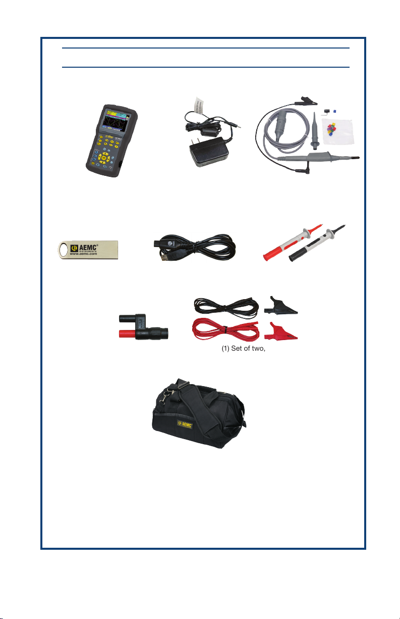
PRODUCT PACKAGING 2150.21
Shipping Contents:
Handscope Oscilloscope
Model OX5042
(1) USB thumbdrive
(software and manual)
(1) USB Cable + Driver
(1) BNC Adapter
Cat. #2118.46
(1) U.S. Wall Plug 18W,
100-240V, 50/60Hz
Cat. #5000.51
Cat. #2135.41
(1) Set of two,
color-coded leads and clips
Cat. #2140.63
(1) Black Tool Bag
Cat. #2133.72
(2) Probe 10:1 600V/BNC-M
Cat. #5000.50
(1) Set of two, color-coded probes
Cat. #2152.23
Also Included:
(1) Test Report
(1) Battery Information Sheet
(6) 1.2V NiMH rechargeable batteries 2700mA/h
USB thumbdrive CONTENTS: The SX-METRO software and the Handscope’s complete
user manual.
Page 4
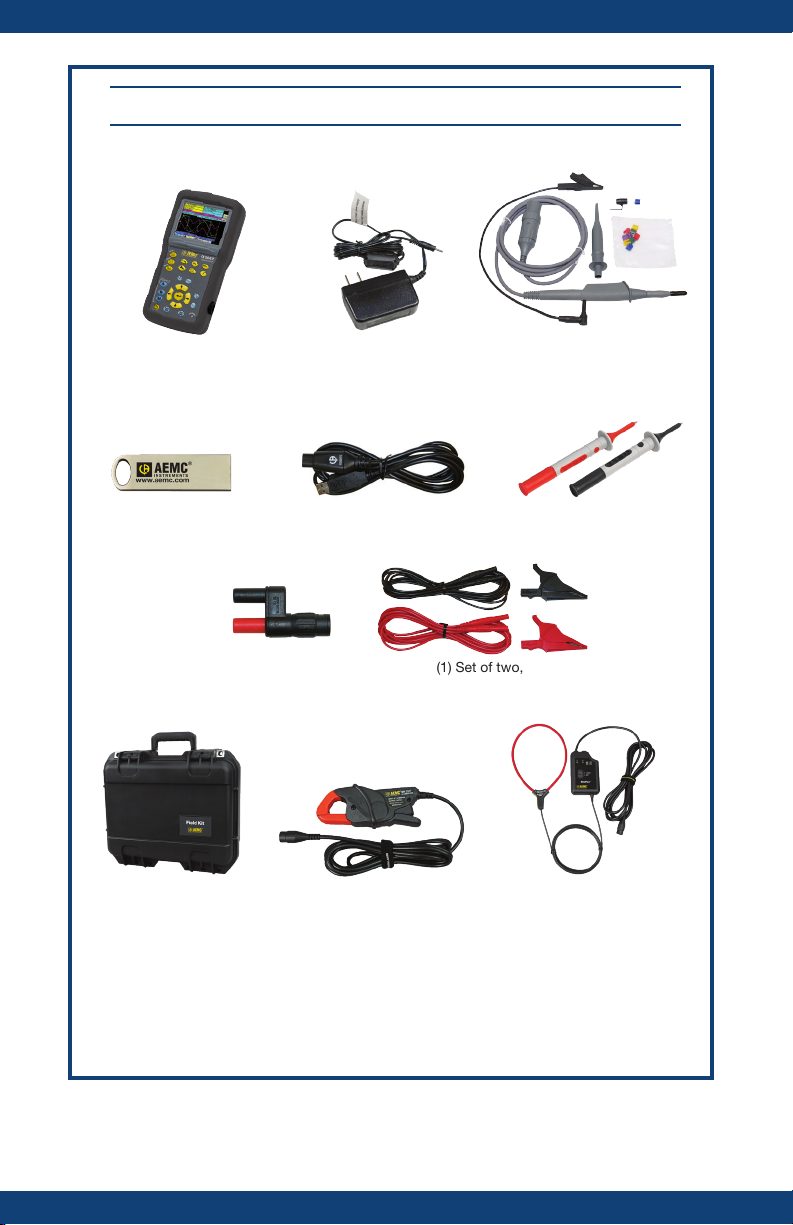
PRODUCT PACKAGING 2150.22 KIT
Shipping Contents:
Handscope Oscilloscope
Model OX5042
(1) USB thumbdrive
(software and manual)
(1) BNC Adapter
Cat. #2118.46
(1) Carrying Case
Cat. #2155.77
(1) U.S. Wall Plug 18W,
100-240V, 50/60Hz
Cat. #5000.51
(1) USB Cable + Driver
Cat. #2135.41
(1) Set of two,
color-coded leads and clips
Cat. #2140.63
(1) Current Probe MN251T
Cat. #2132.59
(1) Probe 10:1 600V/BNC-M
Cat. #5000.50
(1) Set of two, color-coded probes
Cat. #2152.23
(1) Current Probe MF3000-24-1-1
Cat. #2132.63
Also Included:
(1) Test Report
(1) Battery Information Sheet
(6) 1.2V NiMH rechargeable batteries 2700mA/h
USB thumbdrive CONTENTS: The SX-METRO software and the Handscope’s complete
user manual.
Page 5

Precautions Before Use
The operator and/or the responsible authority must carefully read and completely
understand the precautions before use. If you use this instrument in an unspecified
manner, the protection it ensures can be compromised, thus putting you in danger.
• This instrument is designed for use:
- indoors
- in a level 2 pollution environment
- at an altitude below 2000 m
- at a temperature between 0° C and 40° C
- with a relative humidity of less than 80% up to 35° C.
• The safety of all systems, including the instrument, is the responsibility of the
operator.
• It can be used for measurements on 600V CAT III circuits, relative to the ground/
earth.
• Before each use, check the condition of the insulation on the cables, boxes,
sensors and accessories. Any element on which the insulation is damaged
(even partially) must be taken out of service for repair or disposal.
• Respect the environmental and storage conditions.
• The external power supply must be connected to the instrument and to the
network
(98 to 264 VAC).
• The power supply to the instrument is fitted with an automatically resettable
electrical protection after disappearance of the fault.
• As a safety measure, only use factory supplied parts and accessories.
• It is advised to use individual safety protection whenever the environmental
situations in which the instrument is used require it.
• When handling the sensors or test probes, do not place your fingers beyond the
physical guard.
• If the battery housing cover is absent, damaged or incorrectly positioned, the
instrument must not be used other than to adjust the sensors.
Definition of Measurement Categories (CAT)
CAT IV Measurement category IV corresponds to measurements taken at the source
of low-voltage installations.
Example: power feeders, counters and protection devices.
CAT III Measurement category III corresponds to measurements on building installa-
tions.
Example: distribution panel, circuit-breakers, machines or fixed industrial
devices.
CAT II Measurement category II corresponds to measurements taken on circuits
directly connected to low-voltage installations.
Example: power supply to domestic electrical appliances and portable tools.
Page 6

Symbols Used
CAUTION! Risk of electric shock. The voltage at the
parts marked with this symbol may be dangerous.
Warning: Risk of danger. Refer to the operating manual to find out the nature of
the potential hazards and the action necessary to avoid such hazards.
Earth/Ground
Dual insulation
The trash can with a line through it means that in the European Union, the product must undergo selective disposal for the recycling of electric and electronic
material, in compliance with Directive WEEE 2002/96/EC.
The CE marking guarantees conformity with European directives and with regulations covering EMC.
Application or withdrawal not authorized for non-insulated conductors carrying
dangerous voltage levels
Power Supply
The oscilloscope is supplied with one external power supply and set of 6 x 1.2V NiMH
rechargeable batteries 2700mA/h.
When the supplied wall plug is connected from the instrument to an external power
source, battery power is not needed. The batteries are only used when there is no
external power supply available.
Before the first use, start by fully charging the battery.
NOTE: The batteries automatically begin recharging when the Oscilloscope is powered off, but
connected to an external power supply.
When the batteries are recharging, the Battery Charge LED on the front panel will turn
on steady.
The LED will blink in the following situations:
• pre-charge of very low batteries
• temperature is too low or too high
• batteries are damaged
When the charge is complete, the LED will turn off.
If the batteries need to be replaced, they must be replaced with NiMH rechargeable
batteries. Battery charge life is guaranteed for same-capacity batteries (in mAh) as
those shipped with the oscilloscope.
To remove the battery cover, use a coin to turn the slot on the back of the unit counter-
clockwise.
Page 7

Description
The Handscope Oscilloscope Model OX5042-CK combines three instruments into one:
• 40MHz oscilloscope
• Independent 8000-count multimeter with power measurements
• Built-in harmonic analyzer out to the 31st harmonic (fundamental between 40
and 450Hz)
The instrument operates at a constant acquisition depth of 2500 points.
An LCD TFT screen is used to view the applied signals along with all the setting
parameters.
The main command functions are accessible using the buttons on the front panel.
A graphic interface is used to:
- adjust the parameters related to the selected button
- navigate using a horizontal main menu showing the current settings and
vertical sub-menus
Channel Isolation
The two oscilloscope input channels are isolated from each other and from the ground/
earth and the main power supply block. This isolation is provided by double or reinforced insulation, in compliance with the safety standards IEC 61010-1 and IEC 610102-030.
This makes it possible to make measurements on installations or systems connected to
the electricity supply network for voltages of up to 600V in CAT III. The common mode
authorized between the two channels is 600V in CAT III. Thus the operator, the test
systems and the environment are completely protected at all times.
Any voltage (even dangerous) on one channel will not be present on the other channel.
The low points of the inputs are completely insulated, so there is no possibility of the
low points looping (which can be dangerous and highly destructive).
NOTE: The use of accessories with a voltage and/or category lower than 600V CAT III reduces
the operating range to the lower voltages and/or categories.
The oscilloscope is rated 600V CAT III; at least 600V CAT III accessories must be used.
Page 8
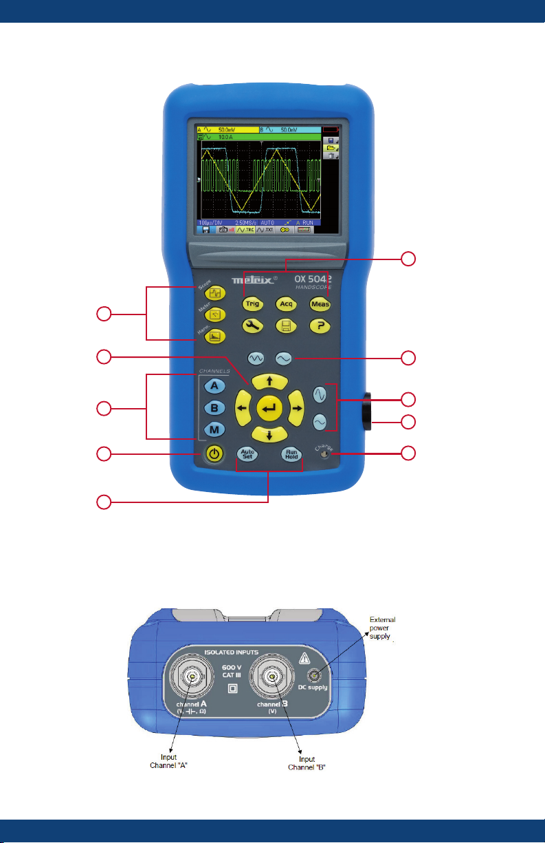
Control Features
1
10
2
3
4
5
Measurement Terminals
9
8
7
6
Page 9

ITEM BUTTON DESCRIPTION
OPERATING MODE BUTTONS
Press these buttons to select the desired operating mode:
1
2
3
- Oscilloscope
- Multimeter
- Harmonic analyzer
NAVIGATION BUTTONS
Use these navigation buttons to move around the menus and dialog
boxes:
VERTICAL
- Vertical movement and automatic selection in the secondary menus
- Adjustment of values in the main menus
- Vertical movement in a dialog box
HORIZONTAL
- Horizontal movement through the main menus
- Adjustment of values in the secondary menus
- Horizontal movement in a dialog box
ENTER
- Opens a dialog box from a main menu or a secondary menu
- Validation of the items in a dialog box
CHANNEL A, B
- A single press selects channel A (or B) and shows the corresponding
menu.
- Pressing twice deselects the channel.
MATH/MEMORY BUTTONS
- A single press selects channel M (Math) and shows the corresponding
menu.
- Pressing twice deselects the channel.
NOTE: For the M (memory) channel, pressing twice invalidates the channel. Pressing once again selects the Math channel, the memory is lost and
must be reloaded.
ON/OFF BUTTON
4
5
6
- The instrument is turned ON by a short press on this button. It is
turned OFF by a long press (a shutdown message appears and a beep
sounds).
FUNCTION BUTTONS
- Auto Set: Performs an automatic adjustment on channels A and B.
The success of each vertical autoset conditions the activation of the
channel.
- Run Hold: Starts or stops an acquisition.
CHARGE STATUS
- Battery Charge LED
Page 10

ITEM BUTTON DESCRIPTION
OPTICAL COMMUNICATOR
7
8
9
10
- Provides the communication between the oscilloscope and a PC.
TIME BASE BUTTONS
- increases the time base for acquisition up to 200 s.
- decreases the time base for acquisition down to 25 ns.
SENSITIVITY BUTTONS
- decreases the vertical sensitivity of the last selected channel down to
5mV.
- increases the vertical sensitivity of the last selected channel up to
200V.
NOTE: For the M channel, the “sensitivity” buttons vary the amplitude
factor but only if a math channel is validated.
MENU BUTTONS
- displays the main “Trigger” menu
- displays the main “Tools” menu
- displays the main “Acquisition” menu
- displays the main “Memory” menu
- displays the main “Measurement/Cursor” menu
- displays the “Help” window
Page 11

Use of the 10:1 Probes
Distribution of stray capacitors:
Considering the stray capacitances, it is imperative to correctly connect the reference
conductors for each probe The conductors should preferably be connected to the cold
points to avoid the transmission of noise by the stray capacitance between modes.
The noise of the digital ground (earth) is sent to the analog input by the stray capacitance.
NOTE: In order to prevent electric shocks or possible fires, never use accessories on which the
casing is accessible if it has a voltage of > 30Vrms compared to the ground.
10:1 Probe Calibration
To obtain optimum response, the probe’s low frequency compensation must be
adjusted.
NOTE: To carry out this adjustment, the two channels of your oscilloscope must be
disconnected from the measured circuits before opening the battery housing cover.
Page 12

The calibration output (3Vpp, 1kHz) for the probe is underneath the battery cover.
To remove the battery cover, use a coin to turn the slot on the back of the unit counter-
clockwise.
Connect the probe to be
adjusted to the calibration
• Select the DC coupling for the channel to which the probe is connected and run
an Autoset
• Adjust the sensitivity and the vertical offset of the channel so that the signal fills
the screen, and adjust the time base to 200µs to view a signal period on the
screen.
• Turn the BNC base of the probe in order to access the probe adjustment screw:
output under the battery housing
cover, as shown.
to carry out pre-setting.
In this example, the probe is over-compesated:
an overshoot occurs.
Turn the screw in either direction until the
signal is horizontal and looks like the screen
shown opposite. Your probe is now calibrated.
Turn the BNC base again to close access to
the adjustment screw and replace the battery
cover.
Remote Programming
The oscilloscope can be programmed remotely from a computer by using the SXMETRO software, which is located on the CD-ROM supplied with your instrument. This
software is used to:
• Configure the instrument
• Perform measurements and retrieve the results
• Transfer files (traces, configuration, screenshots, etc.)
To communicate between the instrument and the computer:
• Connect the USB end of the cable to one of the PC’s USB ports (if necessary
install the driver shipped with the cable).
• Connect the optical connector to the oscilloscope, after first powering it up.
• Open SX-METRO; select USB communications and wait for communication to
be established (in the event of a problem, refer to the SX-METRO instructions).
Page 13

Repair and Calibration
To ensure that your instrument meets factory specifications, we recommend that it be
scheduled back to our factory Service Center at one-year intervals for recalibration, or
as required by other standards or internal procedures.
For instrument repair and calibration:
You must contact our Service Center for a Customer Service Authorization Number
(CSA#). This will ensure that when your instrument arrives, it will be tracked and processed promptly. Please write the CSA# on the outside of the shipping container. If the
instrument is returned for calibration, we need to know if you want a standard calibration, or a calibration traceable to N.I.S.T. (Includes calibration certificate plus recorded
calibration data).
Ship To: Chauvin Arnoux
15 Faraday Drive
Dover, NH 03820 USA
Phone: (800) 945-2362 (Ext. 360)
(603) 749-6434 (Ext. 360)
Fax: (603) 742-2346 or (603) 749-6309
E-mail: repair@aemc.com
(Or contact your authorized distributor)
Costs for repair, standard calibration, and calibration traceable to N.I.S.T. are available.
NOTE: You must obtain a CSA# before returning any instrument.
®
, Inc. d.b.a. AEMC® Instruments
Technical and Sales Assistance
If you are experiencing any technical problems, or require any assistance with the
proper operation or application of your instrument, please call, mail, fax or e-mail our
technical support team:
Chauvin Arnoux®, Inc. d.b.a. AEMC® Instruments
Phone: (800) 945-2362 (Ext. 351) • (603) 749-6434 (Ext. 351)
Fax: (603) 742-2346
E-mail: techsupport@aemc.com
Page 14

Limited Warranty
The Model OX5042 are warranted to the owner for a period of two years from the date
of original purchase against defects in manufacture. This limited warranty is given by
AEMC® Instruments, not by the distributor from whom it was purchased. This warranty
is void if the unit has been tampered with, abused or if the defect is related to service
not performed by AEMC® Instruments.
Full warranty coverage and registration is available on our website:
www.aemc.com
Please print the online Warranty Coverage Information for your records.
What AEMC® Instruments will do:
If a malfunction occurs within the warranty period, you may return the instrument to
us for repair, provided we have your warranty registration information on file or a proof
of purchase. AEMC® Instruments will, at its option, repair or replace the faulty material.
Register your product online at www.aemc.com
Warranty Repairs
What you must do to return an Instrument for Warranty Repair:
First, request a Customer Service Authorization Number (CSA#) by phone or by fax
from our Service Department (see address below), then return the instrument along
with the signed CSA Form. Please write the CSA# on the outside of the shipping container. Return the instrument, postage or shipment pre-paid to:
®
Ship To: Chauvin Arnoux
15 Faraday Drive
Dover, NH 03820 USA
Phone: (800) 945-2362 (Ext. 360)
(603) 749-6434 (Ext. 360)
Fax: (603) 742-2346 or (603) 749-6309
E-mail: repair@aemc.com
Caution: To protect yourself against in-transit loss, we recommend you insure your
returned material.
You must obtain a CSA# before returning any instrument.
, Inc. d.b.a. AEMC® Instruments
Page 15

NOTES:
Page 16

02/18
99-MAN 100462 v3
Chauvin Arnoux®, Inc. d.b.a. AEMC® Instruments
15 Faraday Drive • Dover, NH 03820 USA • Phone: (603) 749-6434 • Fax: (603) 742-2346
www.aemc.com
 Loading...