

Page 1
ENGLISH
■
GROUND TESTER
6418
User Manual
Page 2

Statement of Compliance
Chauvin Arnoux®, Inc. d.b.a. AEMC® Instruments
certifies that this instrument has been calibrated using
standards and instruments traceable to international
standards.
We guarantee that at the time of shipping your
instrument has met its published specifications.
An N.I.S.T. traceable certificate may be requested at
the time of purchase, or obtained by returning the
instrument to our repair and calibration facility, for a
nominal charge.
The recommended calibration interval for this
instrument is 12 months and begins on the date of
receipt by the customer. For recalibration, please use
our calibration services. Refer to our repair and
calibration section at www.aemc.com
Serial #:
.
Catalog #: 2141.03
Model #: 6418
Please fill in the appropriate date as indicated:
Date Received:
Date Calibration Due:
Chauvin Arnoux®, Inc.
d.b.a AEMC
®
Instruments
www.aemc.com
2 Clamp-On Ground Tester Model 6418
Page 3

Table of Contents
PRECAUTIONS FOR USE ..................................................... 5
1. I
NTRODUCTION ................................................................... 7
1.1. Function Keys .................................................................. 8
1.2. Display ............................................................................. 8
1.3. Inserting Batteries ............................................................ 9
1.4. Date and Time Setup ....................................................... 9
2. OPERATION .................................................................... 10
2.1. General .......................................................................... 10
2.2. Impedance and Current Measurement .......................... 10
2.3. Current Measurement .................................................... 12
2.4. Configuring (Set-up) ....................................................... 13
2.5. Errors ............................................................................. 15
2.6. Automatic Stop .............................................................. 15
2.7. Storage .......................................................................... 16
3. TECHNICAL CHARACTERISTICS ................................. 18
3.1. General Reference Conditions ...................................... 18
3.2. Electrical Characteristics ............................................... 18
3.3. Influences ...................................................................... 19
3.4. Power Supply................................................................. 22
3.5. Environmental Conditions .............................................. 22
3.6. Mechanical Characteristics ............................................ 22
3.7. Compliance with International Standards ...................... 23
3.8. Electromagnetic Compatibility (EMC) ............................ 23
4. M AINTENANCE ............................................................. 24
4.1. Cleaning ......................................................................... 24
4.2. Battery Replacement ..................................................... 24
LIMITED WARRANTY .......................................................... 26
Clamp-On Ground Tester Model 6418 3
Page 4
Thank you for purchasing the AEMC Clamp-On Ground Tester Model
instructions whenever this danger symbol appears.
Application or withdrawal authorized on conductors carrying
032.
The product has been declared recyclable after analysis of its
regulations covering EMC.
In the European Union, the product must undergo selective
compliance with Directive WEEE 2002/96/EC.
6418.
F
or best results from your instrument and for your safety, read the
enclosed operating instructions carefully and comply with the
precautions for use. These products must be only used by qualified and
trained users.
WARNING, risk of DANGER! The operator must refer to these
Equipment is protected by double insulation.
Battery.
dangerous voltages. Type A current sensor per IEC 61010-2-
U
seful information or tip to read.
life cycle in accordance with the ISO14040 standard.
Guarantees conformity with European directives and with
disposal for the recycling of electric and electronic material, in
Definition of Measurement Categories (CAT)
CAT IV Measurement category IV corresponds to measurements taken
at the source of low-voltage installations.
Example: power feeders, counters and protection devices.
CAT III Measurement category III corresponds to measurements on
building installations.
Example: distribution panel, circuit-breakers, machines or fixed
industrial devices.
CAT II Measurement category II corresponds to measurements
taken on circuits directly connected to low-voltage
installations.
Example: power supply to domestic electrical appliances
and portable tools.
4 Clamp-On Ground Tester Model 6418
Page 5
PRECAUTIONS FOR USE
This instrument is compliant with safety standard IEC 61010-2-032, for
voltages up to 100V in category IV or 150V in category III. Failure to
observe the safety instructions may result in electric shock, fire,
explosion, and destruction of the instrument and of the installations.
The operator and/or the responsible authority must carefully read an
c
learly understand the various precautions to be taken in use. T
ator and/or the responsible authority must carefully read an
oper
learly understand the various precautions to be taken in use. Sou
c
nowledge and a keen awareness of electrical hazards are essential
k
when using this instrument.
If you use this instrument other than as specified, the protection it
provides may be compromised, thereby endangering you.
The safety of any system in which this instrument might
i
ncorporated is the responsibility of the integrator of the system.
Do not use the clamp above its rated frequency, since this might
cause it to overheat dangerously.
Do not use the instrument on networks of which the voltage or
category exceeds those mentioned.
Observe the environmental conditions of use.
Do not use the instrument if it seems to be damaged, incomplete, or
poorly closed.
Before each use, check the condition of the insulation on the housing.
Any item of which the insulation is deteriorated (even partially) must
be set aside for repair or scrapping.
Before using your instrument, check that it is perfectly dry. If it is wet,
it must be thoroughly dried before it can be connected or used.
When handling the instrument, keep your fingers behind the physical
guard.
Avoid impacts on the measurement head, in particular the air gap.
Keep the surfaces of the air gap clean; even a little dirt can cause the
clamp to malfunction.
Use personal protection equipment systematically.
All troubleshooting and metrological checks must be done by
competent accredited personnel.
be
he
d
nd
d
Clamp-On Ground Tester Model 6418 5
Page 6

Receiving Your Shipment
Upon receiving your shipment, make sure that the contents are
consistent with the packing list. Notify your distributor of any missing
items. If the equipment appears to be damaged, file a claim immediately
with the carrier and notify your distributor at once, giving a detailed
description of any damage. Save the damaged packing container to
substantiate your claim.
Ordering Information
Clamp-On Ground Tester Model 6418 .............................. Cat. #2141.03
Ω
Includes hard carrying case, 5
wrist strap, Bluetooth adapter, multilingual safety sheet, Quick Start
Guide, and USB drive containing User Manual.
calibration loop, four 1.5V AA batteries,
Replacement Parts
Hard Carrying Case .......................................................... Cat. #2141.52
5 Ω Calibration Loop ......................................................... Cat. #2141.51
or the accessories and replacement parts, visit our web site:
F
www.aemc.com
6 Clamp-On Ground Tester Model 6418
Page 7
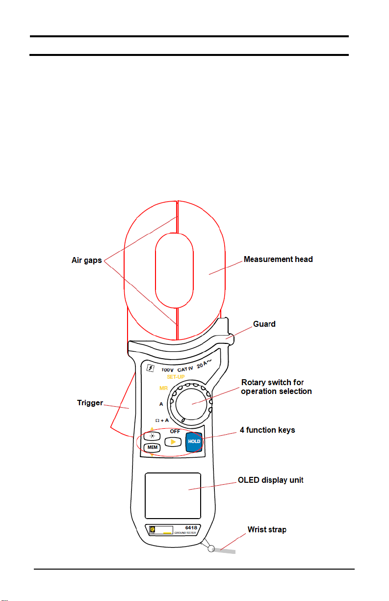
1. INTRODUCTION
The simple-to-use Clamp-On Ground Tester Model 6418 makes ground
impedance measurements in a parallel earth network, such as power
distribution poles and overhead ground conductors. These
measurements are simpler to perform than traditional measurements
with two auxiliary rods.
The Model 6418 can make accurate low value ground impedances
measurements and AC current measurements. Its large oblong
measurement head can clamp around bars up to 1.18 x 1.57” (30 x
40mm). Its memory function records measurements for later viewing.
The instrument’s OLED (Organic Light Emitting Diode) display screen is
easy to read, even in direct sunlight.
Clamp-On Ground Tester Model 6418 7
Page 8

1.1. FUNCTION KEYS
MEM
Record the measurement displayed.
HOLD
Freeze/unfreeze the display of the measurement.
▲
Browse in:
Memory read (MR).
►
When switch is set to:
the date/time.
As a general rule, functions shown in white on the keys are available
when the switch is set to Ω+A or A. The yellow arrow keys (▲, ▼ and
►) are available when the switch is set to MR or SET-UP.
Key Function
Switch the display unit backlighting ON and OFF.
▼
.2. DISPLAY
1
SET-UP menu and change the value of the parameter
selected.
Ω+A or A: a long press on ► activates/deactivates the
audible signal.
SET-UP: ► browses in the menu and confirms the changes
made.
MR: ► toggles the display between the measurement and
the instrument displays OR.
8 Clamp-On Ground Tester Model 6418
When the measurement exceeds the limits of the measurement range,
Page 9

1.3. INSERTING BATTERIES
The year blinks, indicating it can
Then press the ► key; the month
Confirm by pressing ►. The
Refer to §4.2.
1.4. DATE AND TIME SETUP
The first time you turn ON the instrument by turning the switch to Ω+A,
the instrument prompts you to set the date.
be edited. Set it using the ▲ and
▼ keys
P
.
ress ►. The date blinks; set it
using ▲ and ▼ and confirm by
pressing ►.
hours reading blinks. Set it
using ▲ and ▼ and confirm
by pressing ►.
blinks. Set it using ▲ and ▼.
The instrument then displays the
time format. Choose 24h or 12h (A
or P) using ▲ and ▼.
The minutes reading blinks. Set
it using ▲ and ▼ and confirm
with ►.
Clamp-On Ground Tester Model 6418 9
Page 10

2. OPERATION
2.1. GENERAL
Press the trigger to open the jaws,
and clamp around the conductor
that is part of the ground system
to be measured.
When the jaws are open, the
symbol
instrument cannot make a
measurement.
When turned ON, the instrument performs self-calibration. The jaws of
the clamp must therefore be closed and not clamped around any
conductor.
If the instrument fails to complete self-calibration, the error message Err.
CAL is displayed. If this happens, turn the instrument OFF and ensure
the air gaps are clean. Then turn the instrument ON.
2.2. IMPEDANCE AND CURRENT MEASUREMENT
Set the
switch to
Ω+A.
10 Clamp-On Ground Tester Model 6418
is displayed and the
Page 11

2.2.1. CONNECTION
During the impedance measurement, the instrument emits an
eliminated.
The ground electrode to be measured (RX) is in a series/parallel
arrangement with other ground electrodes via the earth impedance (Z
and physical connection to other resistance paths (Z
impedance will be slightly greater than R
impedance is very low. For example: If R
assuming the downstream
X
is 21Ω and ZS/R1-Rn is
X
). The measured
S
effectively 0.6Ω, the Model 6418 will read 21.6Ω.
intermittent audible “beeping” signal. This is caused by the
measurement frequency that flows in the measurement head.
The sound can vary as a function of the frequency and amplitude
of the current measured. This sound is normal and cannot be
)
E
2.2.2. FREEZING AND/OR STORING A MEASUREMENT
When the measurement has stabilized, you can press the HOLD key to
freeze it and/or MEM to record it.
Clamp-On Ground Tester Model 6418 11
Page 12
2.2.3. AUTO-HOLD FUNCTION
measured flows.
The AUTO-HOLD function (see §2.4), freezes the measurement
automatically when the jaws of the clamp are opened. This can be useful
when you have only one hand free to make a measurement.
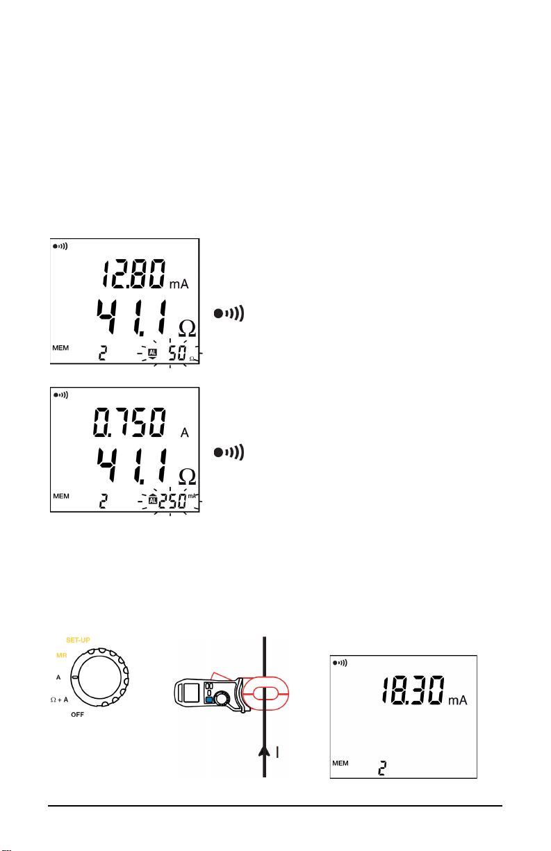
2.2.4 ALARMS
To facilitate making measurements, you can program an alarm on the
impedance measurement (see §2.4) and/or the current measurement
(see §2.4). You can then be aware whether the measurement is
acceptable without looking at the display.
The alarm indicator on the display
blinks and the instrument emits a
continuous audible signal.
To eliminate the audible signal, press
and hold the ► key.
I
f you set alarms on both the
impedance and the current, and both
alarm thresholds are exceeded, the
alarm on the current has priority.
2.3. CURRENT MEASUREMENT
The current measurement alone is identical to the current measurement
with the impedance measurement.
Set the switch to
A.
12 Clamp-On Ground Tester Model 6418
Press the trigger to open the jaws of the clamp and
clamp the conductor in which the current to be
Page 13

When the measurement has stabilized, you can press the HOLD key to
CLR (erase memory) menu.
SND menu (activation of the sound).
STOP menu (automatic standby).
ALΩ menu (impedance alarm).
Confirm by pressing ►.
freeze it and/or MEM to record it in memory. You can also use the
AUTO-HOLD function (see §2.4) to freeze the measurement
automatically when the clamp jaws are opened. This can be useful when
you have only one hand free to make a measurement. To facilitate
making measurements, you can configure an alarm on the current
measurement value (see §2.4).
2.
4. CONFIGURATION (SET-UP)
Set the switch to SET-UP.
Use the ▼ and ▲ keys to scroll through the screens of the SET-UP
menu.
Press the ► key to enter the CLR menu.
To cancel, press ►.
To erase all records, press and hold the ▲ and ▼ keys
simultaneously. The instrument emits 5 audible beeps before
erasing the memory.
Press ► to enter the SND menu. Use ▲ and ▼ to display or
hide the symbol.
When is displayed, the instrument emits an audible
signal when keys are pressed and when alarm thresholds are
crossed.
Confirm by pressing ►.
During the measurements (when the switch is set to Ω+A or
A), a long press on ► activates/deactivates the audible
signal.
Press ► to enter the STOP menu. Use ▲ and ▼ to display
or hide the symbol (permanent operation).
When is displayed, automatic switching of the instrument to
standby at the end of 5 minutes is disabled. Confirm by
pressing ►.
Press ► to enter the ALΩ menu. Use ▲ and ▼ to scroll
through the display:
Clamp-On Ground Tester Model 6418 13
: no impedance alarm.
: impedance alarm activates when impedance >10Ω.
: impedance alarm activates when impedance <10Ω.
Press ►; the alarm threshold blinks. Set it using ▲ and ▼.
Acceptable values are between 1 and 199Ω. A long press
scrolls the values faster.
Page 14

AL A menu (current alarm).
Press ► to enter the AL A menu. Use ▲ and ▼ to scroll
DATE menu (setting of the date)
HOUR menu (setting of the time)
HOLD menu (activation of the AUTO-HOLD function)
VER menu (display of the software version)
CAL menu (not used)
through the display:
: no current measurement alarm.
: current alarm activates when current >30mA.
Press ►; the alarm threshold blink. Set it using ▲ and ▼.
Acceptable values are between 1mA and 20.0A. A long press
scrolls the values faster.
Press ► to confirm.
Press ► to enter the DATE menu. Use ▲ and ▼ to set the
year. Press ►; the month setting blinks. Set it using ▲ and
▼.
Do the same for the day setting and confirm with the ► key.
For a more detailed procedure, see §1.4.
Press ► to enter the HOUR menu. Use ▲ and ▼to choose
24h or 12h (A or P) form. Press ►; the hours setting blinks.
Set this using ▲ and ▼. Press ►; the minutes setting blinks.
Set this using ▲ and ▼; confirm by pressing ►.
For a more detailed procedure, see §1.4.
Press ► to enter the AUTO-HOLD menu. Use ▲ and ▼ to display
or hide the symbol. When this symbol is displayed, the
AUTO-HOLD function is activated. In this mode, when the
measurement is stable, it is frozen when the clamp is opened.
Confirm by pressing ►.
Press ► to display the software version number.
Press ▼ to display the instrument serial number.
14 Clamp-On Ground Tester Model 6418
Page 15

2.5. ERRORS
Display of the NOISE symbol during the impedance
When the current exceeds 10A, the impedance
When the impedance measurement is >1200Ω, the
When the current measurement is >20A, the
When the impedance measurement is <1Ω, the display
During the measurement, the instrument reports any errors.
measurement indicates that the current (>5A) or voltage
(ZxI> 25V) is too high, making the accuracy of the
displayed measurement uncertain.
measurement is not displayed (dashes appear in the
measurement field).
instrument displays OR.
instrument so indicates.
alternately indicates the measured value and LOOP,
indicating the value is very low for a valid ground
impedance measurement and most likely indicates the
measurement is through a wire loop rather than through
the earth.
2.6. AUTOMATIC STOP
After 5 minutes of inactivity, the instrument enters to standby mode.
Press any key or turn the switch to any setting to exit standby. The
instrument restarts without repeating the calibration procedure if it has not
been on standby for more than 15 minutes. It is possible to disable
automatic standby; refer to §2.4 (STOP menu). The symbol is then
displayed.
Clamp-On Ground Tester Model 6418 15
Page 16
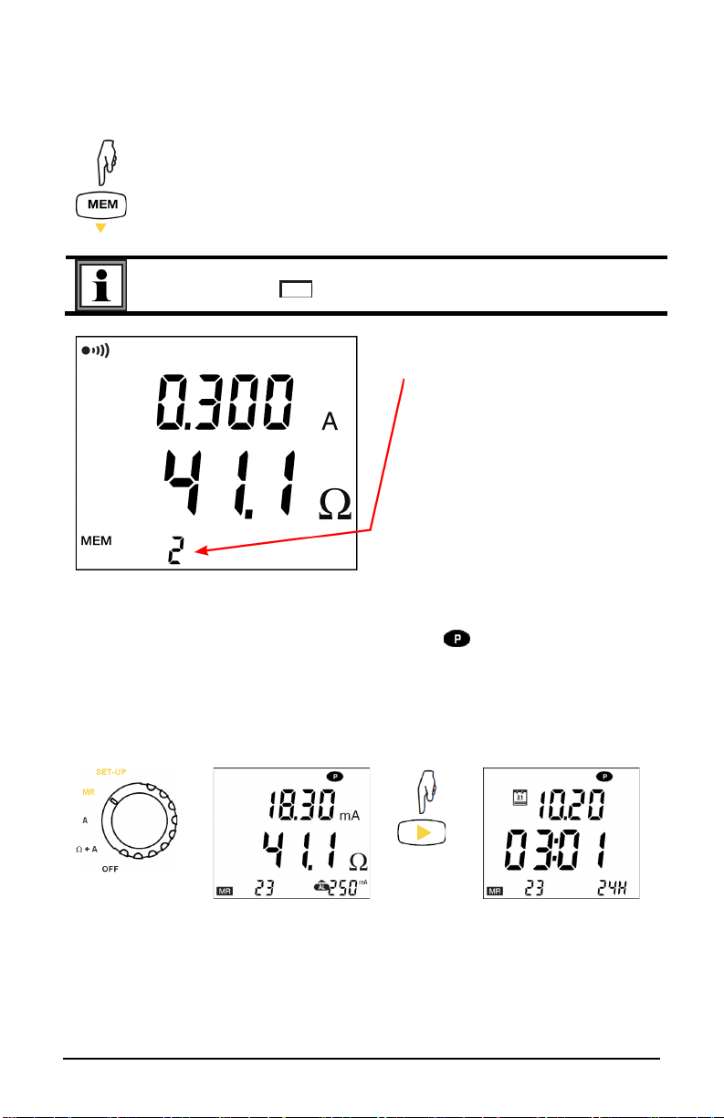
2.7. STORAGE
To record a measurement, press the MEM key.
To record a measurement, the batteries must not be
The measurement is
switch to MR.
2.7.1. RECORDING A MEASUREMENT
You can first press the HOLD key to freeze the measurement.
discharged (the symbol must not be displayed).
recorded in the memory slot
of which the number is
displayed (in this example,
slot number 2).
I
t is recorded with all
accompanying information:
date and time
any alarms and their
status (triggered or not)
any errors (NOISE, OR,
LOOP)
ancillary displays (HOLD,
)
2.7.2. VIEWING RECORDINGS
Set the
The instrument displays the last measurement
recorded. Press ► to display the date and time.
U
se ▲ and ▼ to scroll through all of the recorded measurements.
16 Clamp-On Ground Tester Model 6418
Page 17
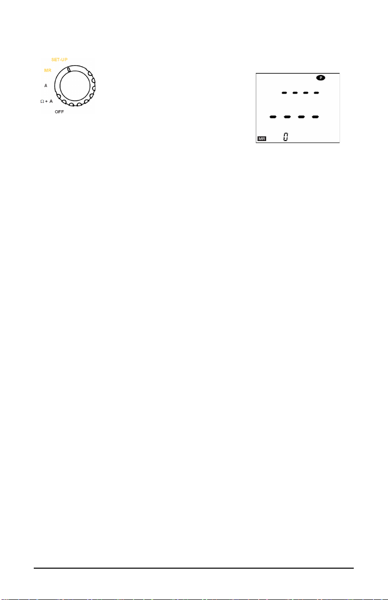
2.7.3. ERASING ALL RECORDINGS
Set the switch to SET-UP.,
empty.
then follow the procedure
described in
§2.4 in the CLR
menu.
When you return to the MR
setting, the instrument
indicates that the memory is
7.4. MEMORY FULL
2.
You can record up to 300 measurements (numbered from 0 to 299).
If yo
u continue recording, measurement number 300 overwrites
measurement number 0, measurement 301 overwrites measurement 1,
and so on.
The instrument reports this by alternately displaying FULL and the
memory slot number.
Y
ou can continue in this way up to number 9999, at which point
recording becomes disabled and you must erase the memory to be able
to resume recording.
Clamp-On Ground Tester Model 6418 17
Page 18
3. TECHNICAL CHARACTERISTICS
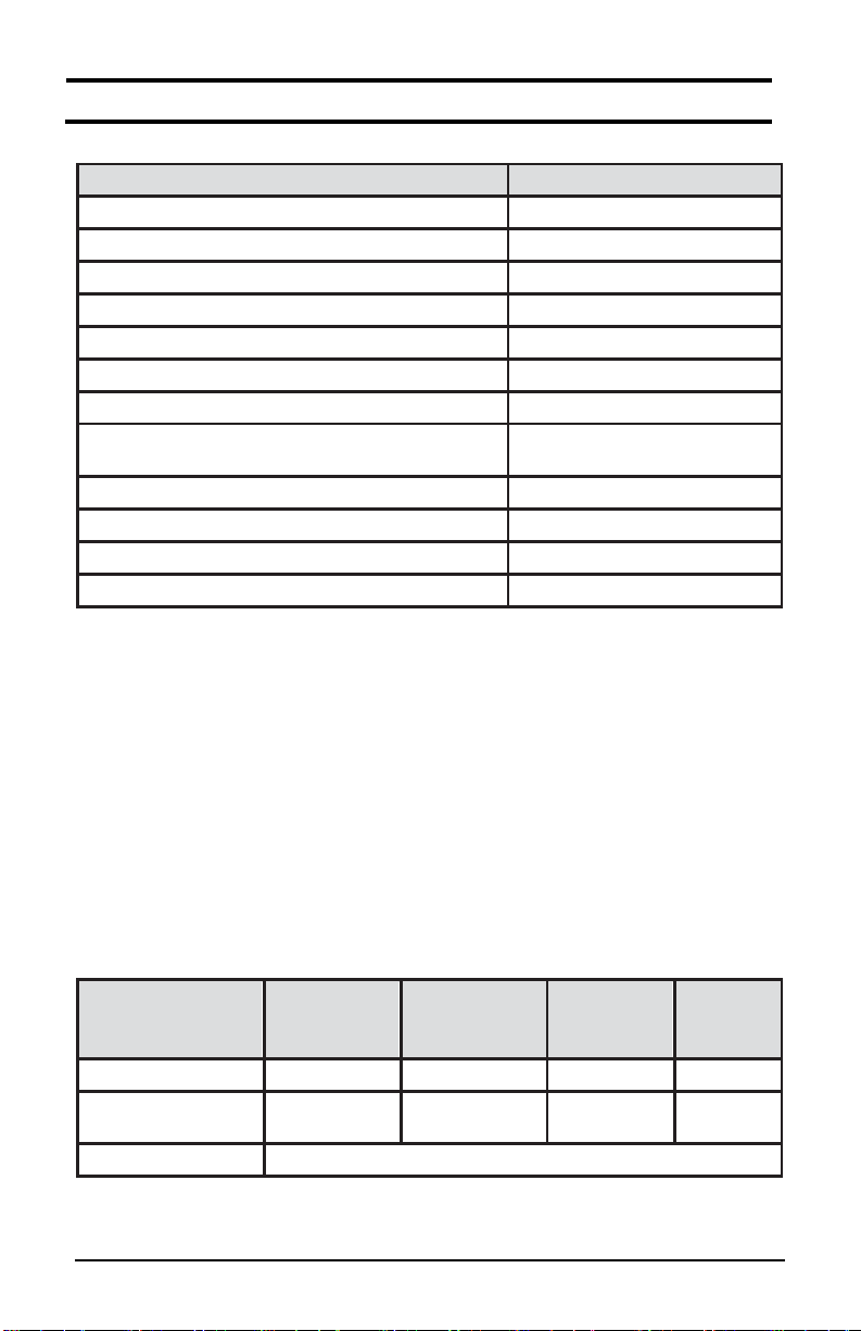
3.1. GENERAL REFERENCE CONDITIONS
Quantities of influence
Reference values
Temperature
73 ±5°F (23 ±3°C)
Relative humidity
50 ±10%RH
Supply voltage
6 ±0.2V
Electric field
<1V/m
Magnetic field
<40A/m
Operating position
clamp horizontal
Position of the conductor in the jaws
centered
Adjacent conductors carrying current in
impedance measurement
At least 3.9” (10cm)
Magnetic mass
At least 3.9” (10cm)
Frequency
50Hz, sinusoidal
Level of distortion
<0.5%
Current present in impedance measurement
0mA
range
Intrinsic
uncertainty (δ)
0.01Ω)
ct)
2 ct)
R +
2 ct)
The intrinsic uncertainty is the error defined under the conditions of
reference.
The operational uncertainty is the intrinsic uncertainty plus the
variation of the quantities of influence (position, supply voltage,
temperature) as defined in standard IEC 61557. The uncertainties are
expressed as a percentage of the reading (R) and as a number of
display counts (ct): ±(a%R+# ct).
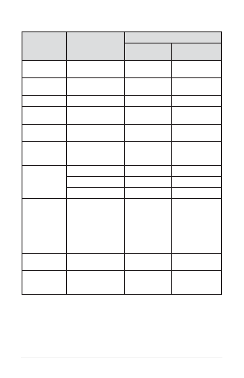
3.2. ELECTRICAL CHARACTERISTICS
3.2.1. IMPEDANCE MEASUREMENTS
Particular conditions of reference
Inductance in series with the resistance: zero.
Specified
measurement
Resolution (ct) 1 mΩ 10 mΩ 100 mΩ 1 Ω
No-load voltage ≤ 45 mV to 2083 Hz
18 Clamp-On Ground Tester Model 6418
0.010 to
0.099Ω
± (1.5%R +
0.10 to
0.99Ω
± (1.5%R + 2
1.0 to
49.9Ω
± (1.5%R +
50 to
149Ω
± (2.5%
Page 19

Specified
range
Intrinsic
uncertainty (δ)
2 ct)
2 ct)
± (15%R +
2 ct)
+ 2 ct)
range
Resolution (ct)
50 µA
100 µA
1 mA
10 mA
Intrinsic
uncertainty (δ)
± (2%R +
200 µA)
± (2%R + 1 ct)
± (2%R +
1 ct)
± (2%R +
1 ct)
Resolution (ct)
100 mA
Intrinsic uncertainty (δ)
± (2%R + 1 ct)
measurement
Resolution (ct) 5 Ω 10 Ω 10 Ω 50 Ω
No-load voltage ≤ 45 mV to 2083 Hz
150 to
245Ω
± (5%R +
250 to 440Ω 450 to
640Ω
± (10%R +
± (20%R
3.2.2 CURRENT MEASUREMENTS
Particular conditions of reference
Frequency of the signal 47 to 800Hz
650 to
1200Ω
Specified
measurement
Specified measurement range 3.00 to 20.00 A
0.500 to
9.950mA
10.00 to
99.90mA
Beyond 20A and 800Hz, the clamp may overheat dangerously.
3.2.3. STORAGE
Number of records: 300.
3.
3. INFLUENCES
Z = impedance
I = current
δ = intrinsic uncertainty given in §3.2.
ct = resolution given in §3.2.
100.0 to
299.0mA
0.300 to
2.990A
Clamp-On Ground Tester Model 6418 19
Page 20

Impedance measurement:
Influence
Typical
Maximum
-4 to 131°F (-20 to
+ 55 °C)
Relative
humidity
10 to 90% RH
Supply
voltage
4 to 6.5 V
Z < 450 Ω
0.5 δ ± ct
Z < 450 Ω
1 δ ± ct
0.5 δ ± ct
1 δ ± ct
Proximity to
mass
Sheet steel
against air gap
Magnetic field
50/60Hz
Z < 250 Ω
0.25 δ ± ct
0.4 δ ± ct
Z < 250 Ω
0.5 δ ± ct
0.8 δ ± ct
Z x I <
20 V
20 V ≤ Z x
I < 40 V
40 V ≤
Z x I
Z ≥ 100 Ω
0.5 δ ± ct
1 δ ± ct
Ground
inductance
Instrument displays Z at measurement frequency
(2083Hz)
Quantities of
influence
Temperature
Position of
conductor
Position of
clamp
magnetic
Adjacent
conductor
Leakage
current in the
grounding
system from
50 to 60Hz
I <10 A. ZxI
<75 V
Range of
influence
from the edge to
the center
+/- 180°
1mm thick
30 A/m
I < 40A
Z <
100 Ω
0.5 δ / 10°C ± ct 1.5 δ / 10°C + ct
1 δ ± ct 2 δ ± ct
0.05 δ ± ct 0.1 δ ± ct
Z ≥ 450 Ω
0.2 δ ± ct
Z < 450 Ω
0.25 δ ± ct
Z ≥ 450 Ω
0.1 δ ± ct 0.5 δ ± ct
0.05 δ ± ct 0.1 δ ± ct
Z ≥ 250 Ω
0.5 δ ± ct 1 δ ± ct
1 δ ± ct 3 δ ± ct
2 δ ± ct 4 δ ± ct
0.4 δ ± ct
Z < 450 Ω
0.5 δ ± ct
Z ≥ 450 Ω
Z ≥ 450 Ω
Z ≥ 250 Ω
0 to 500 µH
20 Clamp-On Ground Tester Model 6418
Page 21
Current measurement:
Quantities of
influence
Temperature
Relative
humidity
Supply voltage 4 to 6.5 V
Position of
conductor
Position of
clamp
Proximity to
magnetic mass
Magnetic field
50/60Hz
Deformation of
the leakage
current
Range of influence
-4 to 131 °F (-20 to +
55 °C)
10 to 90% RH
from the edge to the
center
+/- 180°
Steel sheet 1mm
thick against air
gap
10 A/m 0.75 mA 1.5 mA
30 A/m 2 mA 4.5 mA
100 A/m 8 mA 15 mA
IEC 61557-13
5% to 150 Hz
at 0°
6% to 250 Hz
at 180°
5% to 350 Hz
at 0°
Influence
Typic
al
0.5 δ / 10°C ± ct 1.5 δ / 10°C + ct
0.5 δ ± ct 1 δ ± ct
0.05 δ ± ct 0.1 δ ± ct
0.05 δ ± ct 0.2 δ ± ct
0.1 δ ± ct 0.25 δ ± ct
0.1 δ ± ct 0.2 δ ± ct
0.05 δ ± ct 0.1 δ ± ct
Maxim
um
Adjacent
conductor
Frequency of
the leakage
current
1:
For the whole current measurement range
Clamp-On Ground Tester Model 6418 21
I < 40A > 70 dB > 66 dB
47 to 800 Hz 1
0.5 δ ± ct 1 δ ± ct
Page 22

3.4. POWER SUPPLY
%RH
1 = Domain of reference
The instrument is powered by four 1.5V AA batteries (LR6 alkaline; NiMH
rechargeable can also be used). The voltage range ensuring proper
operation is 4 to 6.5V. The battery life of the instrument is 12 hours
(approximately 1440 30-second measurements).
3.
5. ENVIRONMENTAL CONDITIONS
The conditions of ambient temperature and relative humidity are
illustrated in the following graph:
2 = Domain of use
3 = Domain of storage
without batteries.
Indoor use
Altitude <6500’ (<2000m)
Pollution degree 2
3.6. MECHANICAL CHARACTERISTICS
Dimensions (L x W x H): 11.8 x 4.2 x 2.2” (300 x 106 x 56mm)
Weight: approximately 2.6 lb (1.2kg)
Clamping diameter: 1.26” (32mm) or a 1.18 x 1.57” (30 x 40mm) or 0.79
x 2.17” (20 x 55mm) bar
Ingress protection: IP40 per IEC 60529
22 Clamp-On Ground Tester Model 6418
Page 23

3.7. COMPLIANCE WITH INTERNATIONAL STANDARDS
The instrument is compliant with standard IEC 61010-1 and IEC 610102-032, 100V category IV or 150V category III.
3.8. ELECTROMAGNETIC COMPATIBILITY (EMC)
The instrument is compliant with standard IEC 61326-1.
Clamp-On Ground Tester Model 6418 23
Page 24

4. MAINTENANCE
Except for batteries, the instrument contains no parts
replaceable by personnel who are not specially trained and
accredited. Any unauthorized repair or replacement of a
part by an “equivalent” may gravely impair safety.
4.1. CLEANING
Disconnect everything connected to the instrument and set the switch to
OFF. Use a soft cloth, dampened with soapy water. Rinse with a damp
cloth and dry rapidly with a dry cloth or forced air. Do not use alcohol,
solvents, or hydrocarbons. Do not use the instrument again until it has
completely dried. Keep the air gap of the clamp perfectly clean.
4.2. BATTERY REPLACEMENT
The symbol on the display screen blinks when batteries are low.
This symbol is displayed steadily when the batteries require
replacement.
1. Disconnect everything connected to the instrument and set th
witch to OFF.
s
2. Turn the instrument over and unscrew the 2 captive screws securing
the battery compartment cover.
e
24 Clamp-On Ground Tester Model 6418
Page 25

3. Remove the battery compartment cover.
point.
Instrument date and time settings are saved for several minutes,
them when it is turned ON (see §1.4).
4. Remove the batteries from the compartment.
Spent batteries must not be treated as ordinary household
waste. Take them to the appropriate recycling collection
nsert new batteries in the compartment, observing polarities.
5. I
6. Replace the battery compartment cover and ensure it is completely
rrectly closed.
co
7. Screw the two captive screws back in.
long enough for you to change the batteries. If, however, the
date and time are lost, the instrument will prompt you to reset
Clamp-On Ground Tester Model 6418 25
and
Page 26

LIMITED WARRANTY
Y
our AEMC instrument is warranted to the owner for a period of two
years from the date of original purchase against defects in manufacture.
This limited warranty is given by AEMC
®
Instruments, not by the
distributor from whom it was purchased. This warranty is void if the unit
has been tampered with, abused, or if the defect is related to service not
performed by AEMC
®
Instruments.
Full warranty coverage and product registration is available on our
website at:
ww.aemc.com/warranty.html.
w
Please print the online Warranty Coverage Information for your records.
®
W
hat AEMC
Instruments will do:
If a malfunction occurs within the two-year period, you may return the
instrument to us for repair, provided we have your warranty registration
information on file or a proof of purchase. AEMC
®
Instruments will, at its
option, repair or replace the faulty material.
WARRANTY REPAIRS
What you must do to return an Instrument for Warranty Repair:
F
irst, request a Customer Service Authorization Number (CSA#) by
phone or by fax from our Service Department (see address below), then
return the instrument along with the signed CSA Form. Please write the
CSA# on the outside of the shipping container. Return the instrument,
postage or shipment pre-paid to:
®
S
hip To: Chauvin Arnoux
, Inc. d.b.a. AEMC® Instruments
15 Faraday Drive • Dover, NH 03820 USA
Phone: (800) 945-2362 (Ext. 360)
(603)749-6434 (Ext. 360)
Fax: (603)742-2346 • (603) 749-6309
E-m
ail: repair@aemc.com
C
aution: To protect yourself against in-transit loss, we recommend you
insure your returned material.
OTE: You must obtain a CSA# before returning any instrument.
N
26 Clamp-On Ground Tester Model 6418
Page 27

NOTES:
Clamp-On Ground Tester Model 6418 27
Page 28

04/19
99-MAN 100482 V2
Chauvin Arnoux®, Inc. d.b.a. AEMC® Instruments
15 Faraday Drive • Dover, NH 03820 USA
Phone: (603) 749-6434 • Fax: (603) 742-2346
www.aemc.com
 Loading...