

Page 1
MICRO-OHMMETER
6250
ENGLISH
User Manual
Page 2

Statement of Compliance
Chauvin Arnoux®, Inc. d.b.a. AEMC® Instruments
certifies that this instrument has been calibrated
using standards and instruments traceable to
international standards.
We guarantee that at the time of shipping your
instrument has met its published specifications.
An NIST traceable certificate may be
requested at the time of purchase, or obtained
by returning the instrument to our repair and
calibration facility, for a nominal charge.
The recommended calibration interval for this
instrument is 12 months and begins on the date of
receipt by the customer. For recalibration, please
use our calibration services. Refer to our repair
and calibration section at www.aemc.com.
Serial #: ________________________________
Catalog #: 2129.81
Model #: 6250
Please fill in the appropriate date as indicated:
Date Received: _________________________________
Date Calibration Due: _______________________
Chauvin Arnoux®, Inc.
d.b.a AEMC® Instruments
www.aemc.com
Page 3
READ CAREFULLY BEFORE
USING FOR THE FIRST TIME
Your instrument is equipped with a NiMH battery. This technology oers several
advantages:
• Long battery charge life for a limited volume and weight.
• Possibility of quickly recharging your battery.
• Signicantly reduced memory eect: you can recharge your
battery even if it is not fully discharged.
• Respect for the environment: no pollutant materials such as lead
or cadmium, in compliance with the applicable regulations.
After prolonged storage, the battery may be completely discharged. If so, it must
be completely recharged.
Your instrument may not function during part of this recharging operation.
Full recharging of a completely discharged battery may take several hours.
NOTE: In this case, at least 5 charge/discharge cycles will be necessary
for your battery to recover 95% of its capacity.
To make the best possible use of your battery and extend its eective service life:
• Only use the charger supplied with your instrument. Use of
another charger may be dangerous.
• Only charge your instrument at temperatures between 0° and 40°C.
• Comply with the conditions of use dened in the operating manual.
• Comply with the storage conditions specied in the operating
manual.
NiMH technology allows a limited number of charge/discharge cycles depending
signicantly on:
• The conditions of use.
• The charging conditions.
Please refer to § 9 for correct replacement of the battery.
Do not dispose of the battery pack with other solid waste. Used batteries
must be entrusted to a qualied recycling company or to a company
specialized in processing hazardous materials.
Page 4

Table of Contents
1. INTRODUCTION ................................................................................. 5
1.1 International Electrical Symbols ................................................6
1.2 Denition of Measurement Categories .....................................6
1.3 Receiving Your Shipment ..........................................................6
1.4 Ordering Information .................................................................7
1.4.1 Accessories and Replacement Parts ............................7
2. PRODUCT FEATURES ......................................................................... 8
2.1 Description ................................................................................8
2.2 Applications ..............................................................................9
2.3 Key Features ............................................................................9
2.4 Control Features .....................................................................10
2.5 Button Functions ..................................................................... 11
2.6 Display Symbols .....................................................................12
3. SPECIFICATIONS ............................................................................. 14
3.1 Electrical .................................................................................14
3.2 Mechanical ..............................................................................15
3.3 Display ....................................................................................15
3.4 Environmental .........................................................................16
3.5 Safety ......................................................................................16
4. OPERATION ..................................................................................... 17
4.1 Quick Summary ......................................................................17
4.2 Instrument Conguration (SET-UP Mode) .............................. 19
4.2.1 Program Menu Tree ....................................................19
4.2.2 Programming the 9-Pin Interface Port (rS) ................20
4.2.3 Setting the Buzzer Level (bUZZ) ................................21
4.2.4 Reading the Internal Serial Number (EdSn) ...............21
4.2.5 Reading the Internal Software Version (EdPP) ........... 21
4.2.6 Setting Language for Printing Reports (LAnG) ...........22
2
Micro-Ohmmeter Model 6250
Page 5

4.2.7 Setting the Value for Reference Temperature .............22
4.2.8 Selecting the Method/Value for Ambient Temp ...........23
4.2.9 Selecting the Metal Type (nEtA) .................................24
4.2.10 Programming the Alpha Value (ALPH) ........................24
4.2.11 Selecting Temperature Units (dEg) ............................. 24
4.2.12 Setting Alarm Set Point/Direction/Buzzer Level ..........25
4.2.13 Setting the Display Timeout (LlgH) .............................26
4.2.14 Clearing the Memory (nEn) .........................................26
4.3 Operating Procedure ..............................................................28
4.3.1 Connections and Readings .........................................28
4.3.2 Test Lead Connection ................................................. 29
4.3.3 Very Low Resistance ..................................................29
4.3.4 Meter Readings ..........................................................29
4.3.5 Stand-by (ST BY) State .............................................. 30
4.4 Selecting the Test Range ........................................................ 30
4.5 Measurement Modes ..............................................................31
4.5.1 Measurement Safety Warnings ...................................31
4.5.2 Inductive Resistance Measurement Mode ..................31
4.5.3 Resistance Measurement Mode .................................33
4.5.4 Low Inductive Resistance Measurement Mode ..........34
4.6 Ambient Temperature Compensation .....................................35
4.6.1 Activating the Compensation Function ......................38
4.7 Activating Alarms ....................................................................39
5. MEMORY / PRINTING ...................................................................... 40
5.1 Managing and Printing the Data in Memory .........................40
5.2
Displaying and Printing Stored Measurements ...............................41
5.3 Cables and Printers Used with the Interface Port ...................43
6. DATAVIEW® SOFTWARE ................................................................... 45
6.1 Installing DataView® ................................................................45
6.2 Connecting the Instrument to your Computer .........................49
6.3 Establishing Communication to the Instrument ......................49
6.4 Conguring the Instrument .....................................................50
6.5 Downloading Stored Tests ......................................................52
Micro-Ohmmeter Model 6250
3
Page 6

6.6 Creating a DataView® Report .................................................52
6.7 Exporting the Report to a Spreadsheet or PDF File ..............53
7. TROUBLESHOOTING ........................................................................ 54
7.1 Fault Indicators .......................................................................54
8. APPLICATION EXAMPLES ................................................................ 55
8.1 Measuring Winding Resistance of Motors
and Transformers ....................................................................55
8.2 Measuring Resistance on Electric Motors ..............................56
8.3 Battery Strap Measurements ..................................................56
9. MAINTENANCE ................................................................................ 57
9.1 Warning...................................................................................57
9.2 Cleaning ..................................................................................57
9.3 Charging/Recharging the Battery ...........................................58
9.4 Battery and Fuse Replacement ..............................................59
Repair and Calibration ....................................................................60
Technical and Sales Assistance ......................................................60
Limited Warranty .............................................................................61
Warranty Repairs ............................................................................61
4
Micro-Ohmmeter Model 6250
Page 7

CHAPTER 1
INTRODUCTION
WARNING
These safety warnings are provided to ensure the safety of personnel and proper operation of the instrument.
• Do not attempt to perform any tests with this instrument until you
have read the user manual.
• Tests are to be carried out on de-energized circuits only! Never
connect the unit to a live circuit.
• When the unit is measuring resistance showing a high inductive
component (transformers, motors, etc.) after ending the measurement, the unit then discharges the inductive sample and the
warning icon
the connection wires before this icon disappears.
• The micro-ohmmeter should never be used in an explosive
environment (this includes poorly ventilated battery rooms and
enclosures).
appears for the entire duration. Never disconnect
• Make sure the internal battery is fully charged prior to testing. If the
instrument has been left unused for several months, recharge the
battery.
• We recommend recharging the micro-ohmmeter every month to
ensure a full battery charge when used.
• When replacing fuses, install only fuses which are direct replacements.
• If the case needs cleaning, do not use any alcohol or oil based
cleaners. Preferably use soapy water with a damp cloth or
sponge.
• The test leads and measuring wires must be in good condition and
should be changed if there is any evidence of deterioration (insulation split, burnt, etc.).
• Never exceed the safety values indicated in the specications.
Micro-Ohmmeter Model 6250
5
Page 8
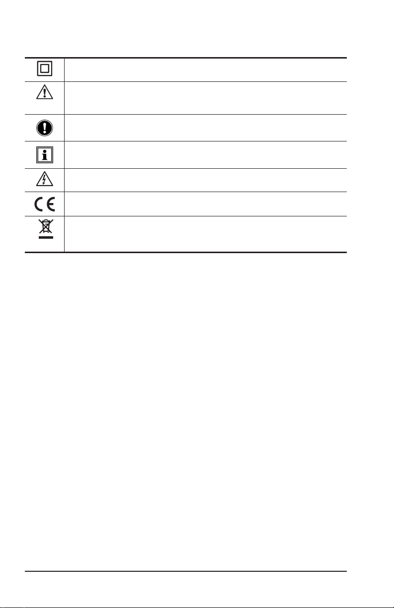
1.1 International Electrical Symbols
This symbol signifies that the instrument is protected by double or reinforced insulation.
CAUTION - Risk of Danger! Indicates a WARNING and that the operator must
refer to the user manual for instructions before operating the instrument in all
cases where this symbol is marked.
Important instructions to read and understand completely.
Important information to acknowledge.
Risk of electric shock. The voltage at the parts marked with this symbol may
be dangerous.
Compliance with the Low Voltage & Electromagnetic Compatibility European
directives (73/23/CEE & 89/336/CEE)
In the European Union, this product is subject to a separate collection system
for recycling electrical and electronic components In accordance with directive
WEEE 2002/96/EC
1.2 Definition of Measurement Categories
CAT II: For measurements performed on circuits directly connected to
the electrical distribution system. Examples are measurements
on household appliances or portable tools.
CAT III: For measurements performed in the building installation at
the distribution level such as on hardwired equipment in xed
installation and circuit breakers.
CAT IV: For measurements performed at the primary electrical supply
(<1000V) such as on primary overcurrent protection devices,
ripple control units, or meters.
1.3 Receiving Your Shipment
Upon receiving your shipment, make sure that the contents are consistent
with the packing list. Notify your distributor of any missing items. If the equip-
ment appears to be damaged, le a claim immediately with the carrier and
notify your distributor at once, giving a detailed description of any damage.
Save the damaged packing container to substantiate your claim.
6
Micro-Ohmmeter Model 6250
Page 9

1.4 Ordering Information
Micro-ohmmeter Model 6250 ............................................ Cat. #2129.81
Includes extra large tool bag, set of two 10ft Kelvin clips (10A - Hippo), one RS-232 DB9 F/F
6 ft null modem cable, RS-232 to USB adapter, US 115V power cord, quick reference guide,
one pad of measurement
supplied with product user manual and DataView® software.
1.4.1 Accessories and Replacement Parts
Kelvin clips (10A Hippo), 10 ft color-coded leads ................Cat. #1017.84
Kelvin clips (10A Hippo), 20 ft color-coded leads ................ Cat. #2118.70
Kelvin probes (1A), spring loaded, 10 ft color-coded leads
with banana plug terminations ............................................. Cat. #2118.73
Kelvin probes (1A), spring loaded, 20 ft color-coded leads
with banana plug terminations ............................................. Cat. #2118.74
Kelvin Probes Pistol Grip 10 ft (10A) Spring Loaded........... Cat. #2118.75
Kelvin Probes Pistol Grip 20 ft (10A) Spring Loaded........... Cat. #2118.76
Kelvin Probes 10 ft (10A) Spring Loaded ........................... Cat. #2118.77
Kelvin Probes 20 ft (10A) Spring Loaded ........................... Cat. #2118.78
Kelvin Clips 10 ft (1-10A) ..................................................... Cat. #2118.79
Kelvin Clips 20 ft (1-10A) ..................................................... Cat. #2118.80
Cable, PC RS-232, DB9 F/F 6 ft Null Modem Cable ........... Cat. #2119.45
Replacement Battery 6V, 8.5 Ah rechargeable NiMH
result forms, NiMH rechargeable 6V battery pack, and USB stick
.......... Cat. #2129.91
RTD temperature probe ....................................................... Cat. #2129.95
RTD temperature probe with 7 ft (2m) extension cable ....... Cat. #2129.96
Fuse, set of 3, 16A/250V, 1 1/4 x 1/4" (6.3x32mm)
fast blow ....................................................................................... Cat. #2129.98
Fuse, set of 10, 2A/250V, 3/4 x 3/16" (5x20mm) fast blow .. Cat. #2129.99
Extra large classic tool bag..................................................Cat. #2133.73
Inverter – 12VDC to 120VAC 200 Watt for vehicle use ......... Cat. #2135.43
115V Power Cord ................................................................Cat. #5000.14
Adapter – RS-232 to USB 2.0 .............................................Cat. #5000.60
Order Accessories and Replacement Parts Directly Online
Check our Storefront at www.aemc.com/store for availability
Micro-Ohmmeter Model 6250
7
Page 10

CHAPTER 2
PRODUCT FEATURES
2.1 Description
The Model 6250 Micro-ohmmeter is used to perform low resistance
measurements from 1μΩ to 2500Ω. There are seven ranges with test
currents from 1mA to 10A.
The front end of the micro-ohmmeter employs a four-wire Kelvin conguration, which eliminates test lead resistance for a measurement accuracy
of 0.05%. A built-in circuit lters out AC signals.
The Model 6250 Micro-ohmmeter is packaged in a sealed eld case well
suited for shop and eld use. Power is supplied by a long-life NiMH battery
pack with a built-in recharger (110/220V).
The large, easy-to-read liquid crystal display is 2.25 x 4.00". It displays
the value of resistance, metal type, reference and ambient temperatures
(if selected), alarm conditions (if selected), test current and range and test
mode (Resistive, Inductive or Auto).
For operator safety and instrument protection, the micro-ohmmeter is
fuse protected at the inputs. Two fuses, accessible behind the front panel,
protect against stored energy in inductive loads.
Enhanced internal circuitry protects against possible inductive kickback
when the current is shut o.
A built-in thermal switch protects the micro-ohmmeter against overheating
on the 10A range when in continuous use.
8
Micro-Ohmmeter Model 6250
Page 11

2.2 Applications
Some of the more popular and most frequent uses of the micro-ohmmeter
are in applications for:
•
Checking metallic coating resistance, especially in aeronautics
• Ground connections and continuity measurement
• Resistance measurements on motors and transformers
• Contact resistance measurements on breakers and switches
• Component measurement
• Electrical cable resistance measurement
• Mechanical bond tests
• Wire to terminal connections
• Aircraft and rail bonds
• Many other very low resistance samples
2.3 Key Features
• Measures from 1µΩ to 2500Ω
• Test current selection from 1mA to 10A
• RTD temperature measurement (optional)
• Automatic or manual temperature compensation
• Two programmable alarms with high or low triggering
• Stores up to 1500 test results
• Selectable Inductive or Resistive test modes
• Operator safety by automatic discharge of residual charge on the
equipment under test
• Instantaneous, continuous or multiple test operation
• Selectable metal type (Copper, Aluminum or other) for
temperature compensation
• Internal, rechargeable batteries conduct up to 5000, 10A tests
• A built-in battery pack recharger recharges the batteries by
connecting to the AC line (90V/264V, 45Hz/420Hz) using a
standard line cord
• 4-Wire measurement with automatic compensation of
undesirable voltages and lead resistance
• Large multi-function backlit display
• Direct display of the measurement with its units, range, measure-
ment mode and, if activated, temperature compensation.
• Measurement can be initiated from the front panel or remotely
through the 9-pin communication port
• Rugged, sealed case
Micro-Ohmmeter Model 6250
9
Page 12
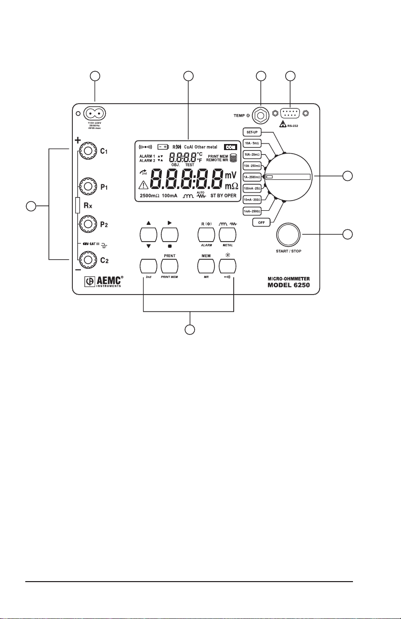
2.4 Control Features
32
1
8
Figure 2-1
54
6
7
1. Kelvin input terminals
2. AC line recharging receptacle
3. Large multi-line backlit liquid crystal display
4. RTD temperature input
5. Communication / remote operation port
6. Range selection switch
7. Test, Start/Stop button
8. Eight program / function buttons
10
Micro-Ohmmeter Model 6250
Page 13

2.5 Button Functions
PRINT
PRINT
MEM
ALARM
METAL
MEM
MR
In SET-UP mode, selects a function or increments a flashing parameter.
In SET-UP mode, selects a function or decrements a flashing parameter
In SET-UP mode, accesses the function to be modified.
In Wrap-Around mode, selects the parameter to be modified (from left to
right)
In SET-UP mode, shifts the decimal point and selects the unit.
Activates the secondary function of a button. The symbol appears on
the left side of the display.
Immediate printing of the measurement to a serial printer. If the temperature
compensation function has been activated, the calculated result and the
temperatures involved are also printed.
Retrieves stored data for printing (this function is independent of the setting
of the switch) except in the OFF and SET-UP positions.
Activates or deactivates the temperature compensation function to calculate the resistance measured at a temperature other than ambient measurement temperature.
Activates or deactivates the alarms. High or low triggering values are
adjusted in SET-UP.
Selects the desired measurement mode prior to starting one of the following measurements: Inductive mode (continuous test), non-inductive mode
(instantaneous test) or non-inductive mode with automatic triggering (multiple tests).
Selects the metal type for the temperature compensation calculation: Cu,
Al, or Other metal.
Stores the measurement at an address identified by an object number
(OBJ) and a test number (TEST).
Two presses on this button are required, one to select the location (use
the ▲ and ► buttons to change the location) and another to store the
measurement.
Retrieves stored data (this function is independent of the selector setting
of the switch) except for the OFF and SET-UP positions. Data is viewed
using the ▲ and ► buttons. The , and ALARM buttons can
be used.
Turns the display backlight ON or OFF.
Activates or deactivates the buzzer and adjusts the sound level.
Micro-Ohmmeter Model 6250
11
Page 14
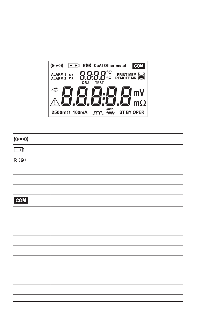
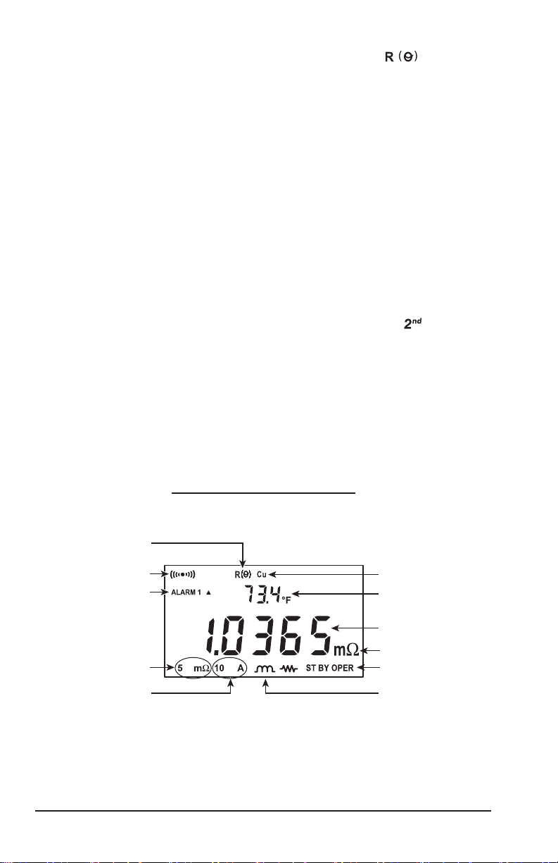
2.6 Display Symbols
The display incorporates two lines of characters to display test results, as
well as a library of symbols to assist the operator in determining conditions
at a glance. The symbols that can appear are shown in Figure 2-2 and are
detailed here.
Figure 2-2
Buzzer ON
Battery condition
Temperature compensation ON
Cu
Al
Other metal
ALARM 1 ▲
ALARM 1 ▼
ALARM 2 ▲
ALARM 2 ▼
OBJ.
TEST
°C / °F
PRINT
MEM
12
Micro-Ohmmeter Model 6250
Copper metal type selected
Aluminium metal type selected
User defined metal type selected
Communication port active
Alarm 1 active with high set point
Alarm 1 active with low set point
Alarm 2 active with high set point
Alarm 2 active with low set point
First position locator for data stored in memory
Second position locator for data stored in memory
Temperature displayed in either degrees Centigrade or Fahrenheit
Printing current test result or tests stored in memory
Displayed measurement about to be stored in memory
Page 15
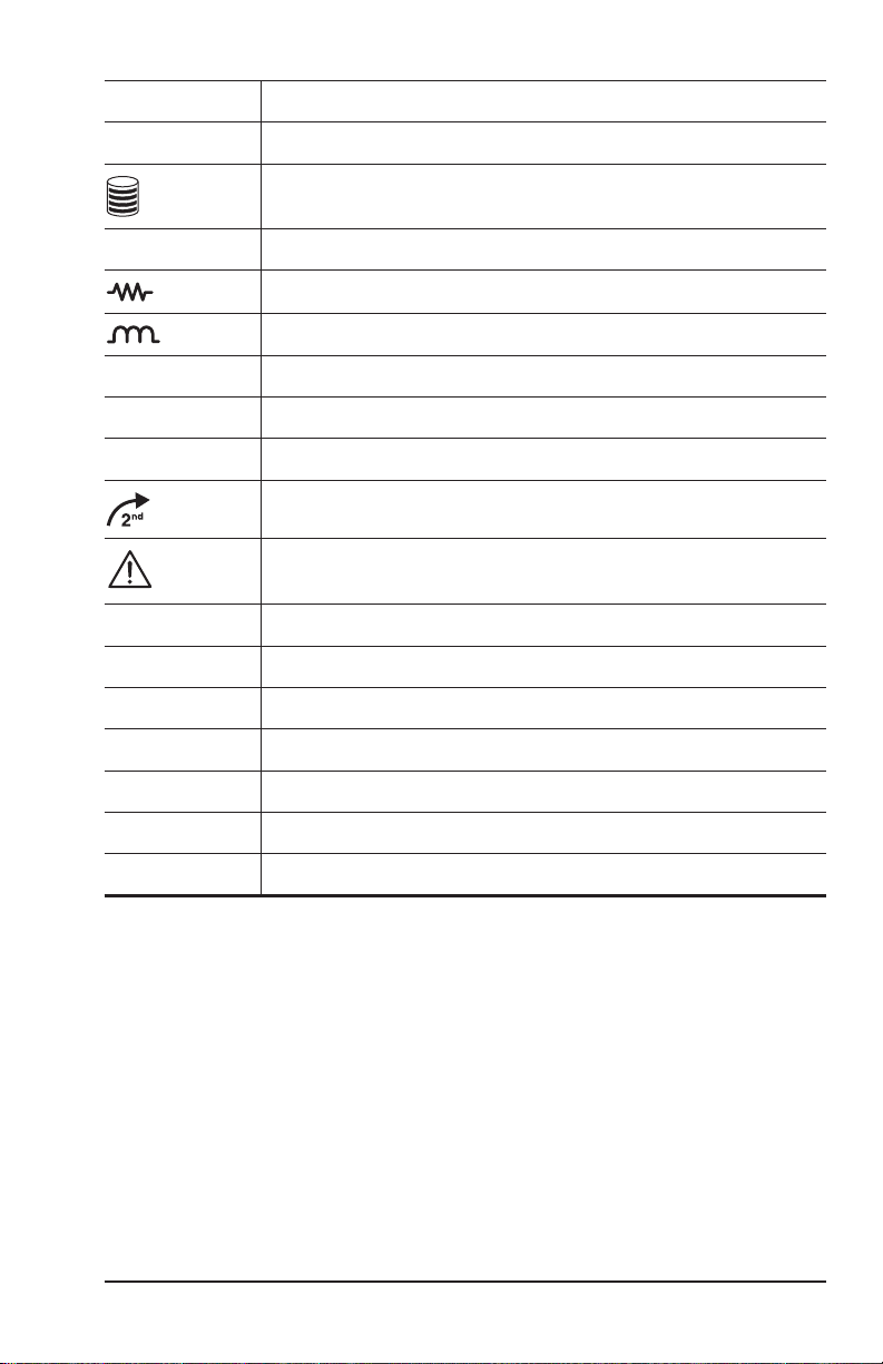
REMOTE
Instrument under computer control
MR
mV mΩ
AUTO
ST BY
OPER
2500Ω 1mA
250Ω 10mA
25Ω 100mA
2500mΩ 1A
Memory recall
Memory utilization indicator
Units of measure
Resistive material test mode selected
Inductive material test mode selected
Repetitive test mode selected
System idle ready to start a test
Test in process
Second function of a button activated
CAUTION! Refer to the user manual before using the instrument.
2500 ohm, 1 milliamp test range selected
250 ohm, 10 milliamp test range selected
25 ohm, 100 milliamp test range selected
2500 milliohm, 1 Amp test range selected
250mΩ 10A
25mΩ 10A
5mΩ 10A
Micro-Ohmmeter Model 6250
250 milliohm, 10 Amp test range selected
25 milliohm, 10 Amp test range selected
5 milliohm, 10 Amp test range selected
13
Page 16
CHAPTER 3
SPECIFICATIONS
3.1 Electrical
Specications are given for an ambient temperature of 23°C ± 5°, relative humidity
of 45 to 75% and a supply voltage of 6V ± 0.1V.
Measurement Method:
4-Wire Kelvin resistance measurement with compensation for stray/residual voltages
Measurement Ranges:
Range Resolution
5mΩ 0.1µΩ 0.15% ± 1.0µΩ 10A 50mV
25mΩ 1µΩ 0.05% ± 3µΩ 10A 250mV
250mΩ 10µΩ 0.05% ± 30µΩ 10A 2500mV
2500mΩ 0.1mΩ 0.05% ± 0.3mΩ 1A 2500mV
25Ω 1mΩ 0.05% ± 3mΩ 100mA 2500mV
250Ω 10mΩ 0.05% ± 30mΩ 10mA 2500mV
2500Ω 100mΩ 0.05% ± 300mΩ 1mA 2500mV
Accuracy over 1 year
23°C ± 5°C
Measurement
Current
Temperature Measurement: 3-wire 100Ω Platinum RTD
Accuracy: ± 0.5°C
Resolution: 0.1°C
Inuence From Environment Conditions:
Temperature: 0.1% per 10°C typical, 0.25% max
Humidity: 0.5% max from 10 to 90%
Battery Voltage: ± 0.1% from 4.5 to 7.5V
Open Circuit Voltage: 7VDC max
Voltage
Drop
14
Micro-Ohmmeter Model 6250
Page 17

Operating Voltage: 5 to 6VDC
Power Source:
Rechargeable 6V, 8.5 Ah NiMH battery pack
Built-in 90 to 256V (45 to 420Hz) charger
Battery Life: 5000, 10A tests (typical)
Battery Charging: 120/240VAC ± 20% (45 to 400Hz) line voltage
Auto-Power O: when battery voltage <5.0V
Low Battery Indication: The
needs to be recharged
Overload Input Protection: 250Vrms
Fuses:
F1 - 1 1/4 x 1/4" (6.3x32mm), fast acting, 16A/250V current source
protection
F2 - 3/4 x 3/16" (5x20mm), fast acting, 2A/250V charging circuit
protection
symbol is displayed when the battery
3.2 Mechanical
Dimensions: 10.63 x 9.84 x 7.09" (270 x 250 x 180mm)
Weight: 8.1 lbs (3.69kg approx) without leads
Case Protection: ABS plastic polycarbonate: watertight to IP64 (cover
closed), water resistant to IP53 (cover open).
Color: Safety yellow case with gray faceplate
3.3 Display
Blue Electroluminescent backlit Liquid Crystal Display (LCD), 2.25 x 4.00"
with icons and two numeric elds for data presentation.
One numeric eld contains 4 digits for displaying ambient and reference
temperature levels on the top line in “temperature compensation” mode.
The other contains 5 digits and is used to display the measured values on
the bottom line. Error messages are also listed on the bottom line.
Micro-Ohmmeter Model 6250
15
Page 18

3.4 Environmental
Operating Temperature:
14° to 132°F (-10° to 55°C), 10 to 80% (non-condensing)
Storage Temperature: -40° to 140°F (-40° to 60°C)
3.5 Safety
EN 61010-1, 50V, CAT III, Pollution Degree 2
Conducted and radiated emission:
EN 55022, class B
EN 61000-3-2
EN 61000-3-3
Immunity:
EN 61000-4-2 electrostatic discharges
EN 61000-4-3 radiated elds
EN 61000-4-5 shock
EN 61000-4-6 conducted disturbances
EN 61000-4-11 voltage drops
EN 61000-4-4 bursts
*Specications are subject to change without notice
16
Micro-Ohmmeter Model 6250
Page 19
CHAPTER 4
OPERATION
NOTE: Charge the instrument fully before use.
4.1 Quick Summary
The following is a summary instruction set that will assist the operator in
performing measurements. For complete details on each function and test
method refer to the operating procedure section (§ 4.3) and instrument
conguration section (§ 4.2) in this manual.
WARNING: Read and follow all safety warnings on page 4 before operating this instrument.
1. Turn the instrument on and select a test range by turning the rotary
switch to the desired position. If the resistance of the device under test
is unknown, start with the highest range (2500Ω) and work down to
increase resolution as necessary.
2. Select the test method best suited for the measurement by press-
ing the button to select inductive (continuous test), resistive
(instantaneous test) or AUTO (multiple testing).
3. Activate the backlight, if necessary, by pressing the button.
4. Activate the buzzer, if desired, by pressing yellow button followed
by the button.
5.
Activate alarms, if desired, by pressing the yellow button followed
by the ALARM button. Successive presses of this two-button sequence
will select Alarm 1, Alarm 2 or both.
6. Select the metal type for the device under test by pressing the yellow
button followed by the METAL button. Successive presses of this
two-button sequence will select Copper (Cu), Aluminum (Al) or Other
metal. This will be needed for temperature compensation.
Micro-Ohmmeter Model 6250
17
Page 20
7. Activate temperature compensation by pressing the button.
Temperature
A
Test current
Resistance measurement
Inductive test mode
The reference temperature will appear followed by the ambient
temperature on the top line of the display.
8. Start the test by pressing the START/STOP button. The resistance
reading will appear on the lower line of the display. The symbol
OPER will appear on the lower left to indicate that a test is in
process. The Stand-by symbol STBY will appear when the test is
completed. Resistive element tests will stop automatically. Inductive
and AUTO testing will stop when the operator pushes the START/
STOP button a second time.
9. Store the test result in memory by pressing the MEM button at the
conclusion of a test. The next available location will be presented on
the top line of the display. To use this location, press the MEM button
a second time.
10.
Recall readings from memory by pressing the yellow button followed by the MEM button. The last measurement stored in location
OBJ: X TEST: X will be displayed. Use the ▲, ▼ and ► buttons to
select the object and test memory location to review. All information
from the measurement is available for review including metal type,
ambient and reference temperatures, resistance at ambient and reference temperatures, test range and test current.
Typical Operational Display
compensation active
Buzzer active
larm 1 hi set point active
Measurement range
Figure 4-1
18
Micro-Ohmmeter Model 6250
Metal type (Copper)
Reference temperature
Measurement units
Test in process
Page 21

4.2 Instrument Configuration (SET-UP Mode)
4.2.1 Program Menu Tree
The menu tree below shows the order in which functions appear in the
Menu and sub-menus of the set up mode.
Set
r5 – OFF – Trig – PC – uT100 – Print
buzz – off – low high
EdSn – displays internal serial number
EdPP – displays firmware number
Lang – Lg Gb – Lg F
trEF – value
tAnb – Prb – nPrb
nEtA – Copper alpha – Aluminum alpha, Other Metal
ALPH – value
dEg – dEgF – dEgC
ALAr – Alarm 1 – Alarm 2
LlgH – t=OFF – t=1 – t=5 – t=10
nEn – dEL – dEL O – Y – n
The cursor buttons ▲, ▼ and ► have the following functions in the
SET-UP menu:
• The up Arrow ▲ button selects the next function to be programmed
in the top level menu and increments the value of the ashing
variable in the sub-menus.
• The down Arrow ▼ button selects the previous function to be programmed in the top level menu and decrements the value of the
ashing variable in the sub-menus.
•
The right arrow ► button selects the function displayed in the top
level menu and moves the cursor one place to the right or validates
the programming in the sub-menus. See Cables and Printer Used
with the Interface Port (§5.3) for proper connections.
Micro-Ohmmeter Model 6250
19
Page 22

4.2.2 Programming the 9-Pin Interface Port (rS)
The 9-pin interface port on the top right side of the front panel can be pro-
grammed to any of ve communication methods. These consist of:
1.
O: Disable input and output functions of the interface port. This
choice saves battery power.
2. Trigger: Enables the remote measurement function.
3. PC: Activates an RS-232 link between a computer and the unit for
conguring the Model 6250 and for conducting tests and storing
results. When activated, the
4. VT100: Activates an RS-232 link between a display terminal and
the Model 6250. When activated, the
display.
5. Print: Activates the RS-232 link between a printer and the Model
6250 for direct printing of test results. When activated, the
will appear on the display.
The RS-232 modes also allow programming of transmission speed. The
baud rate choices are: 4800, 9600, 19200 and 31250.
The required data conguration settings are: 8 bits, no parity, 1 stop bit,
hardware control (CTS).
icon will appear on the display.
icon will appear on the
icon
• Turn the rotary switch to the SET-UP position.
• Press the
display.
• Press the ►
• Press the ► button to accept this setting or press the
to scroll through the other choices of trigger (trlG), PC, Terminal
(ut100) and Print.
• The choices of PC, terminal and print also require a baud rate
selection.
• After selecting PC, ut100 or Print, pressing the ► button will enter
the baud rate selection menu.
• Press the
and 31250. When the desired baud rate is in the display, validate
it by pressing the ► button to return to the top level rS menu. The
icon will appear in the display.
• Proceed to the next programming variable by pressing the
button
20
Micro-Ohmmeter Model 6250
.
▲ button
button
▲ button
until “rS” appears on the top line of the
, OFF will appear in the display.
▲ button
to toggle the choices for 4800, 9600, 19200
▲
Page 23

4.2.3 Setting the Buzzer Level (bUZZ)
• Turn the rotary switch to the SET-UP position.
• Press the ▲ button until “bUZZ” appears on the top line of the
display.
• Press the ► button to scroll through the choices of OFF (no icon
displayed), LOW (small buzzer icon displayed) or HIGH (large
buzzer icon
sponding icon in the top left corner of the display along with the
associated audible sound.
• When the desired sound level is displayed, press the ► button to
accept it and return to the top level of buzzer set-up.
•
To proceed to the next programming variable, press the ▲ button.
displayed). Each choice will display the corre-
4.2.4 Reading the Internal Serial Number (EdSn)
• Turn the rotary switch to the SET-UP position.
• Press the ▲ button until “EdSn” appears on the top line of the
display.
• Press the ► button to scroll through the serial number. There are
10 digits in the serial number. The rst press will display the rst
ve digits. The second press will display the second ve digits.
EXAMPLE: First press displays: t0302
Second press displays: 044-0
Third press displays: 0001 A
• Press the ► button again to return to the top level of the Serial
Number set-up menu.
•
To proceed to the next programming variable, press the ▲ button.
4.2.5 Reading the Internal Software Version (EdPP)
• Turn the rotary switch to the SET-UP position.
• Press the ▲ button until “EdPP” appears on the top line of the
display.
• Press the ► button to display the rmware version.
• Press the ► button again to return to the top level of the Software
Version set-up menu.
•
To proceed to the next programming variable, press the ▲ button.
Micro-Ohmmeter Model 6250
21
Page 24

4.2.6 Setting the Language used for Printing Reports (LAnG)
• Turn the rotary switch to the SET-UP position.
• Press the ▲ button until “LAnG” appears on the top line of the
display.
• Press the ► button to enter the language selection sub-menu.
• Next, press the ▲ button to toggle between English (Lg Gb) or
French (Lg F).
• Press the ► button to validate the selection and return to the top
level of the Language set-up menu.
•
To proceed to the next programming variable, press the ▲ button.
4.2.7 Setting the Value for the Reference Temperature (trEF)
• Turn the rotary switch to the SET-UP position.
•
Press the ▲ button until “trEF” appears on the top line of the display.
• Press the ► button to enter the reference temperature sub-menu.
The current reference temperature will be displayed with the lead-
ing digit ashing.
• Use the ▲ button to change the leading digit. The minus (-) symbol
can also be programmed in this location.
• When the desired value is reached, press the ► button to move
the next digit to the right.
• Use the ▲ button to change this digit, then press the ► button to
again move to the next digit to the right.
• Repeat this process for each of the 5 digit locations.
•
After the 5th digit is programmed, press the ► button again to return
to the top level of the Reference Temperature set-up menu.
•
To proceed to the next programming variable, press the ▲ button.
NOTE: The program limits for the reference temperature are 32.0 to
130.0°F and -10.0 to 130.0°C. Attempting to set values outside these
limits will cause error message “Err23” (Entry Out of Range) to appear in
the display.
22
Micro-Ohmmeter Model 6250
Page 25

4.2.8 Selecting the Method and Value for Ambient
Temperature (tAnb)
• Turn the rotary switch to the SET-UP position.
• Press the
play.
• Press the ► button to enter the ambient temperature sub-menu.
• The rst choice here is to decide if ambient temperature will be
measured using the RTD temperature probe accessory or if it will
be programmed using the same method as described for refer-
ence temperature. “Prb” (measure the ambient temperature using
the RTD probe accessory) or “nPrb” (no probe, manually enter
the ambient temperature) will be displayed, press the
toggle between the two choices.
• If measuring the ambient temperature is desired, press the ►
button when “Prb” is in the display. The lower display will momentarily show dashes “-----” and then return to the top level ambient
temperature menu.
• If manually entering the ambient temperature is desired, press the
► button when “nPrb” is in the display. The ambient temperature
may now be manually entered.
• The current programmed ambient temperature will be displayed
with the leading digit ashing.
• Use the
can also be programmed in this location.
• When the desired value is reached, press the ► button to move
the next digit to the right.
• Use the
again move to the next digit to the right.
• Repeat this process for each of the 5 digit locations.
• After the 5th digit is programmed, press the ► button again to
return to the top level of the ambient temperature set-up menu.
•
To proceed to the next programming variable, press the ▲ button.
▲ button
▲ button
▲ button
until “tAnb” appears on the top line of the dis-
▲ button
to change the leading digit. The minus (-) symbol
to change this digit then press the ► button to
to
NOTE: The program limits for the reference temperature are 32.0 to
130.0°F and -10.0 to 130.0°C. Attempting to set values outside these
limits will cause error message “Err23” (Entry Out of Range) to appear in
the display.
Micro-Ohmmeter Model 6250
23
Page 26

4.2.9 Selecting the Metal Type (nEtA)
• Turn the rotary switch to the SET-UP position.
• Press the
display.
• Press the ► button to toggle through the choices of Copper (Cu),
Aluminum (Al) or Other Metal. With each press of the right arrow
button, the metal type icon appears at the top of the display.
“nEtA” appears on the small display and the ve digit alpha value
appears on the large display and then automatically returns to the
top level of the metal set-up menu.
• To proceed to the next programming variable, press the ▲
button.
▲ button
until “nEtA” appears on the top line of the
4.2.10 Programming the Alpha Value (ALPH)
• Turn the rotary switch to the SET-UP position.
• Press the
display.
• Press the ► button to begin programming the alpha value. See
Table 2 in §4.6 for common alpha values.
• The current alpha value will be displayed with the leading digit
ashing.
• Use the
value is reached, press the ► button to move the next digit to the
right.
• Use the
again move to the next digit to the right.
• Repeat this process for each of the 5 digit locations.
• After the 5th digit is programmed, press the ► button again to
return to the top level of the alpha set up menu
• To proceed to the next programming variable, press the ▲
button.
▲ button
▲ button
▲ button
until “ALPH” appears on the top line of the
to change the leading digit. When the desired
to change this digit, then press the ► button to
4.2.11 Selecting Temperature Units (dEg)
• Turn the rotary switch to the SET-UP position.
• Press the ▲ button until “dEg” appears on the top line of the display.
24
Micro-Ohmmeter Model 6250
Page 27

• Press the ► button to enter the degree units sub-menu.
• Use the
▲ button
to toggle through the choices of Fahrenheit
(dEgF) or Centigrade (dEgC).
• Press the ► button to validate the selection and return to the top
level of the Temperature units set-up menu.
•
To proceed to the next programming variable, press the ▲ button.
4.2.12 Setting Alarm Set Point, Direction and Buzzer Level (ALAr)
• Turn the rotary switch to the SET-UP position.
• Press the
display.
• Press the ► button, Alarm 1 and its set point, direction and buzzer
level will appear with ALARM 1 ashing.
• To modify the settings of Alarm 1, press the ► button. The direction arrow will now be ashing. To modify Alarm 2 press the
button
• When the direction arrow is ashing, it may be changed by pressing the
point) and LOW (▼ activates below set point).
• Next, press the ► button to adjust the buzzer level for this alarm.
The buzzer icon will be ashing. The choices are OFF (no
icon displayed), LOW (small buzzer icon displayed ) or HIGH
(large buzzer icon
pressing the
• Next, program the set point value used to trigger the alarm (ignoring the decimal point) by pressing the ► button. The leading digit
will be ashing. Adjust the digit value using the
press the ► button to move to the next digit to the right.
• Repeat the process for each of the ve digits.
• Press the ► button when the numeric value is set to the desired
number. The decimal point and units (mΩ or Ω) will be ashing.
• Set the desired resolution and units by pressing the
Each press will move the decimal point one place to the right.
Cycling through milliohms and then through ohms.
• To accept the alarm settings once the decimal point and units
are at the desired values, press the ► button. This will bring you
to Alarm 2. Repeat the process as necessary to set Alarm 2’s
conditions.
▲ button
until “ALAr” appears on the top line of the
, ALARM 2 will then be ashing.
▲ button
to toggle between HIGH (▲ activates above set
displayed). The selection is made by
▲ button
while the icon is ashing.
▲ button
▲ button
then
▲
.
Micro-Ohmmeter Model 6250
25
Page 28

• When Alarm 2 is set press the ► button to return to the top level
of the alarm programming menu. “ALAr” will again appear on the
top line and the bottom line will be blank.
•
To proceed to the next programming variable, press the ▲ button.
4.2.13 Setting the Display Timeout (LlgH)
This setting determines the length of time that the backlight will stay on after
the last button press. The choices are OFF (function disabled, backlight
stays on continuously when activated), 1, 5 or 10 minutes.
• Turn the rotary switch to the SET-UP position.
• Press the ▲ button until “LlgH” appears on the top line of the
display.
• Press the ► button, the last programmed value will appear in the
display.
• Press the ▲ button to toggle through the choices of OFF, t=1, t=5
and t=10.
• When the desired length of time is in the display, press the ►
button to validate the selection.
•
To proceed to the next programming variable, press the ▲ button.
4.2.14 Clearing the Memory (nEn)
You can choose to clear the entire memory or the contents of a specic
object.
• Turn the rotary switch to the SET-UP position.
• Press the ▲ button until “nEn” appears on the top line of the
display.
• Press the ► button, “dEL” will appear on the lower line of the
display.
• Toggle between clearing the entire memory (dEL) or a specic
object (dEL O) using the ▲ button.
• To clear a specic object, press the ► button when “dEL. O” is in
the display, the top line will display Obj 01 with the “0” ashing.
Use the arrow buttons to select the object to be deleted.
• The lower display will show “dEL.02” for example if object number
2 is selected for deletion. As you press the ▲ button, the selected
object will increment accordingly.
26
Micro-Ohmmeter Model 6250
Page 29

• Delete the selected object by rst pressing the ► button and
toggling between Yes “dEL. Y” or No “dEL. n”
• Pressing the ► button while “dEL. Y” is in the display will delete
the contents of the selected object. The display will momentarily
display dashes “-----” and then return to display the next highest
object location.
• Pressing the ► button while “dEL. n” is in the display will cancel
the request.
• Repeat this process for each object to be deleted.
• To clear the entire memory contents, turn the rotary switch to the
SET-UP position.
• Press the ▲ button until “nEn” appears on the top line of the
display.
• Press the ► button, “dEL” will appear on the lower line of the
display.
• Delete all data from memory by rst pressing the ► button, then
toggling between Yes “dEL. Y” or No “dEL. n”
• Pressing the ► button while “dEL. Y” is in the display will clear all
memory of stored measurements.
• Pressing the ► button while “dEL. n” is in the display will cancel
the request.
NOTE: Only objects with data stored in them can be accessed.
To return to the beginning of the SET-UP menu, press the ▲ button when
“nEn” is on the top line of the display
Micro-Ohmmeter Model 6250
27
Page 30

4.3 Operating Procedure
C1
Rc
Rx
Rc
WARNING: Before performing the resistance test, verify that the sample
under test is not energized.
4.3.1 Connections and Readings
Clean all surfaces before connecting test leads. Verify a solid connection
between test leads and the sample. Set the range selector switch to the
desired range for the test. If the anticipated resistance is not known, begin
with the highest range (2500Ω) and successively lower the range selection
until adequate resolution is achieved. The START/STOP button will need
to be pressed each time you change ranges. The range selection may be
changed while the instrument is on.
A diagram of the measurement system is shown in Figure 4-2. The
Model 6250 generates a current (I) from the internal voltage source (V).
A voltmeter measures the voltage drop Vx at the Kelvin probe contact
points to the resistance to be measured (Rx) and displays the resistance
measurement (Rx) directly using the formula Rx = Vx / I.
The result is not aected by the other resistances encountered in the current loop (Ri, Rf, Rc), as long as the total voltage drop induced across Rx
remains below the voltage supplied by the source which is between 5 to
6V. The maximum admissible lead resistance level is Rf ≈ (V- Vx) / I. The
use of Kelvin probes helps, as they eliminate the eect of the lead resistance (Rf).
Ri Rf
P2
I
V
x
P2
+
V
C2
Rf
Rf
Rf
Ri = Unit internal resistance Rc = Contact resistance
Figure 4-2
Rf = Lead resistance Rx = Resistance to be measured
28
Micro-Ohmmeter Model 6250
Page 31

4.3.2 Test Lead Connection
The measurement leads are connected using the four binding posts on the
left side of the front panel as shown in Figure 4-3.
Connect the two red leads to terminals C1 and P1. Connect the two black
leads to terminals C2 and P2.
Any drop in the voltage on the load terminals is measured between the two
“voltage” (V) leads, P1 and P2. The current leads (C1 and C2) can deliver
current from 1mA to 10A.
UI
Figure 4-3
4.3.3 Very Low Resistance
When measuring very low resistive values in the µΩ range, the presence
of stray DC currents may aect the accuracy of the measurements. These
currents can be present due to a variety of reasons including chemical or
thermal EMF in samples made of dissimilar metals. These EMFs are automatically compensated for during the measurement process.
The presence of AC interference in the sample under test may cause the
measured value on the display to uctuate. This interference may become
more noticeable in the presence of strong electric elds. The eects of this
interference may be reduced by twisting the leads around each other.
4.3.4 Meter Readings
When testing resistive samples, the meter reading will stabilize within the
rst few hundred milliseconds. On inductive loads (e.g. transformers), the
measurement reading may take from several seconds to a few minutes
to stabilize and depends greatly on the type of equipment and the imped-
ance of the equipment under test. On very large samples such as utility
transformers, 10 to 15 minutes charging time may be necessary.
Micro-Ohmmeter Model 6250
29
Page 32

4.3.5 Stand-by (ST BY) State
This is the position that the Model 6250 returns to at the end of a measure-
ment cycle after:
• the operator presses the START/STOP button during a test
• any changes to the position of the rotary switch
• every low inductive mode measurement
• an error is detected
4.4 Selecting the Test Range
The Model 6250 has seven test ranges to choose from. Table 1 lists the
maximum resistance, test current and resolution for each range.
Resistance Range Test Current Resolution
2500Ω 1mA 100mΩ
250Ω 10mA 10mΩ
25Ω 100mA 1mΩ
2500mΩ 1A 0.1mΩ
250mΩ 10A 10µΩ
25mΩ 10A 1µΩ
5mΩ 10A 0.1µΩ
Table 1
Turn the rotary switch to the desired range, the range and test current
will appear on the lower left side of the display.
Figure 4-4
The Model 6250 is now ready to start a test.
30
Micro-Ohmmeter Model 6250
Page 33

4.5 Measurement Modes
NOTE: For descriptions of all Fault Indicator (Error) codes, refer to
Chapter 7 - “Troubleshooting” in this manual.
4.5.1 Measurement Safety Warnings
WARNING:
• Never use test leads or measuring wires if there is any evidence
of deterioration (insulation split, burnt, etc).
• Never exceed the safety values indicated in the specications.
• Never connect the unit to a live circuit.
• When the unit is measuring resistance showing a high induc-
tive component (transformers, motors, etc.) after ending the
measurement (with the measurement current cut-o), the unit
then discharges this inductance and displays the icon for this
entire duration.
• Never disconnect the connection wires before the icon dis-
appears.
4.5.2 Inductive Resistance Measurement Mode ( )
This mode is intended for performing measurements on inductive devices.
Press the button until the icon shows on the display.
From the Stand-by state, start a test by performing the following:
• Connect the Kelvin probes to the test specimen.
• Press the START/STOP button.
• If the Kelvin probes are incorrectly connected, the display will show
error message “Err 11” (current leads incorrectly connected), or
“Err 12” (voltage leads incorrectly connected). The unit will then
return to the Stand-by state. When the error is corrected, the test
automatically begins again.
Micro-Ohmmeter Model 6250
31
Page 34

• With the current switched o, the residual voltage (V0) across the
100ms
resistor terminals is measured and displayed. If this voltage level
is too high, “Err 13” will be displayed.
• The current (I) is switched on at the start of a measurement and
remains on continuously until the unit is manually returned to the
Stand-by state by pressing the START/STOP button.
• The voltage across the resistor terminals (V1) is measured and
the measurement R = (V1 - V0) / I is displayed.
• All subsequent measurements comprise only a Vn measurement
as V0 remains in memory. The timing sequence for measurement
is shown in Figure 4-5.
NOTE: After ending the measurement, with the current turned off, the 6250
will discharge the device under test as long as the test leads are connected
to the device.
OPER
STBY
I
C
MES
0
1
3
2
n
640ms
1200ms
Figure 4-5
C = connection check
0 = residual voltage measurement (stored)
1,2,3…n = successive voltage measurements across the resistor terminals
• The test is stopped by pressing the START/STOP button.
• Store the measurement by rst pressing the MEM button, then
select the object and test location to store the measurement using
the arrow buttons. When the desired location has been selected,
press the MEM button a second time to complete the data storage
process.
32
Micro-Ohmmeter Model 6250
120ms
Page 35

4.5.3 Resistance Measurement Mode ( )
This mode is intended for measuring contact and metal plating resistance
levels, and as a general rule, any resistance level on material with a time
constant that is less than a few milliseconds.
In this mode, only one measurement is performed per cycle. When the
START/STOP button is pressed, the test current is applied for approximately
400 milliseconds. Residual voltage is measured, a resistance measurement
is taken and the test stops automatically.
The advantages of the resistance mode include:
• Reduced power consumption as the test current is o between
measurements.
• Less heating of the measured resistance.
• Improved compensation of stray voltages as these are measured
and compensated before each resistance measurement.
Press the button until the icon shows on the display.
From the Stand-by state, start a test by performing the following:
• Connect the Kelvin probes to the test specimen.
• Press the START/STOP button.
•
If the Kelvin probes are incorrectly connected, the display will
show error message “Err 11” (current leads incorrectly connected),
or “Err 12” (voltage leads incorrectly connected). The unit will then
return to the Stand-by state. When the error is corrected, the test
can begin again by pressing the START/STOP button.
• With the current switched o, the residual voltage (V0) across the
resistor terminals is measured. If this voltage level is too high,
the unit displays “Err 13” and returns to Stand-by position. (See
Chapter 7 - “Troubleshooting” for all error message descriptions.)
• The current (I) is switched on when the START/STOP button is
pressed.
• The voltage across the resistor terminals (V1) is measured and
then the current is removed.
• The measurement resistance result R = (V1 - V0) / I is displayed
or error message “Err 07” is displayed, if an over range condition
occurs.
Micro-Ohmmeter Model 6250
33
Page 36

The Model 6250 then returns to the Stand-by state at the end of the measurement. The unit is ready to perform another measurement.
OPER
STBY
C
I
MES
100ms
C = connection check
0 = residual voltage measurement
M = measurement of the voltage across the resistor terminals.
O
240ms
360ms
M
Figure 4-6
C
100ms
O
240ms
360ms
M
• Store the measurement by rst pressing the MEM button, then
select the object and test location to store the measurement using
the arrow buttons. When the desired location has been selected,
press the MEM button a second time to complete the data storage
process.
4.5.4 Low Inductive Resistance Automatic Triggering Measurement Mode
This mode is intended only for measuring resistance on material without a
time constant (non-inductive). The use of the spring loaded Kelvin probes
(Cat. #2118.77 or Cat. #2118.78) listed in the accessories section are rec-
ommended for this mode.
From the Stand-by state, start a test by performing the following:
•
Press the button until the AUTO icon shows on the display.
• Press the START/STOP button.
• Connect the probes to the specimen. The unit waits until it detects
that the current and voltage leads are connected correctly.
34
Micro-Ohmmeter Model 6250
Page 37

• Residual voltage (V0) measurement across the resistor terminals
is measured.
• The measurement current (I) is established, the voltage across
the resistor terminals (V1) is measured and the measurement
resistance result R = (V1 - V0) / I is displayed.
• To start a new measurement cycle, Release at least one
probe, and then reconnect it to the next point or specimen.
NOTE: If the range is exceeded, the unit displays “Err 07”. Changing the
range switch position will stop the test cycle and the unit returns to the
Stand-by state. Each measurement taken during the test cycle can be
temperature compensated and stored while the test cycle is running.
• Store the measurement of each specimen or point by rst pressing
the MEM button, then select the object and test location to store
the measurement using the arrow buttons. When the desired location has been selected, press the MEM button a second time to
complete the data storage process.
• The test is stopped by pressing the START/STOP button.
4.6 Ambient Temperature Compensation
Principle
The metals used in the windings of certain devices (for example, the copper
wire used in transformer or motor windings) have high temperature coefcients in the order of 0.4%/°C (for copper or aluminum). This results in
resistance measurements that are highly dependent on the temperature of
the device. Activating temperature compensation will correct for this condition.
The “Temperature Compensation” function can be accessed by pressing
the button before the start of a test in Resistance and Inductive resis-
tance measurement mode. It can also be activated at anytime during Auto
measurement mode.
Its purpose is to compensate the measured or resistance value at the
ambient temperature (whether measured or programmed), to the resistance value that it should have at a reference temperature.
Micro-Ohmmeter Model 6250
35
Page 38

The compensated resistance level is expressed as follows:
R(T
) = R(T
ref
1 + (alpha * T
) * (1 + alpha * T
amb
amb
)
ref
)
Where:
R(T
T
) = the resistance value measured at ambient temperature
amb
= the temperature measured by a Pt100 probe or programmed
amb
by the operator
Alpha = the temperature coecient of the chosen metal (Aluminum,
Copper, “Other metal”)
T
= the programmed reference temperature to which the
ref
measurement is compensated to
The Temperature Coecient of Copper (near room temperature) is +0.393
percent per degree C. This means if the temperature increases 1°C the
resistance will increase 0.393%.
Example: You have 100 feet of 20 gage wire and its resistance is 1.015Ω at
20°C (room temp). If the temperature of the wire goes up 10°C the resistance
will change by 0.0399Ω (10° * 0.00393 / ° * 1.015Ω = 0.0399Ω).
The wire resistance will now be 1.015Ω + 0.0399Ω = 1.0549Ω.
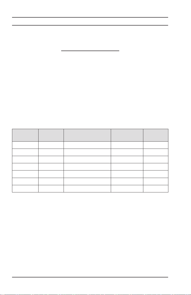
The table below provides the temperature coecients of the more common
metals and alloys.
The Alpha values for Copper and Aluminum are pre-programmed into the
Model 6250. Others may be programmed by selecting Other Metals and
then programming in the alpha constant from the table or other sources.
Material Element/Alloy
Aluminum Element 4.030
Copper Element 3.930
Nickel Element 5.866
Iron Element 5.671
Molybdenum Element 4.579
Tungsten Element 4.403
Silver Element 3.819
Platinum Element 3.729
Gold Element 3.715
Zinc Element 0.847
Steel Alloy 3.000
Nichrome Alloy 0.170
Nichrome V Alloy 0.130
Table 2
36
Micro-Ohmmeter Model 6250
“alpha” per °C
X10
-3
Page 39

A 100Ω platinum RTD can be connected to the front panel of the Model
Pt100 connector
6250 to perform compensated measurements. The temperature sensor
and extension cable assembly, listed in the Accessories section, are recommended. The three pin temperature compensation port is located to the
left of the interface port and is congured as shown in Figure 4-7.
Figure 4-7
To measure the ambient air temperature at the Model 6250, plug the
optional temperature sensor directly into the temperature port on the front
panel as shown in Figure 4-8.
To measure the ambient temperature at the specimen, plug the optional
temperature sensor onto the extension cable and plug the extension cable
into the temperature port on the front panel as shown in Figure 4-9.
Place the temperature sensor in contact with the specimen or in close
proximity to it. Allow 2 minutes for the sensor to normalize to the specimen
temperature before starting a temperature compensated measurement.
Micro-Ohmmeter Model 6250
Figure 4-8
37
Page 40

Figure 4-9
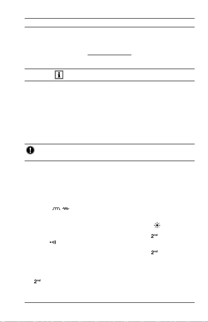
4.6.1 Activating the Compensation Function
Check to ensure that all desired programming and connections are made
correctly. See Setting the Value for Reference Temperature (§4.2.7) and
Selecting the Method for Ambient Temperature (§4.2.8).
• Select the range and the measurement mode.
• Press the button.
The following information will be displayed on-screen:
1.
2. Metal type selected (Cu, Al or Other Metal)
3. Temperature levels T
followed by T
ref
amb
• Press the START/STOP button.
• The unit performs a measurement cycle and directly displays the
compensated resistance value and, depending on set-up, displays
one of the following:
1. The programmed ambient temperature level
2. The temperature level measured by the temperature
sensor
38
Micro-Ohmmeter Model 6250
Page 41

3. “- - - -” if the temperature sensor is activated but is
incorrectly connected or not connected at all
4. The measured temperature is out of range (-10° to 55°C)
If the temperature is out of range or if the sensor leads are disconnected,
the Model 6250 displays “Err 10”.
Temperature compensation can be toggled ON or OFF after the mea-
surement is completed, in resistive and inductive modes or at any time in
AUTO mode.
4.7 Activating Alarms
The alarm programming menu oers the option of choosing one or two
alarm thresholds. An alarm comprises a value, an activation direction
(above ▲ or below ▼ the setpoint) and a sound level setting for the buzzer,
should the alarm become active.
NOTE: Alarms are activated by successively pressing the button fol-
lowed by the ALARM button.
The display will indicate one of the following after each set of button
presses:
• Alarm 1 and the activation direction, ▲ or ▼
• Alarm 2 and the activation direction, ▲ or ▼
• Alarm 1 and Alarm 2 and activation directions, ▲ or ▼ for each
These values and direction parameters are programmable. See Setting
an Alarm Set Point, Direction and Buzzer Levels (§4.2.12). The buzzer will
sound when Alarm 1 and/or Alarm 2 threshold values are reached.
Micro-Ohmmeter Model 6250
39
Page 42

CHAPTER 5
MEMORY / PRINTING
5.1 Managing and Printing the Data in Memory
The memory is organized into locations called Objects and Tests.
There are 99 objects, each containing a maximum of 99 tests (measurements). The maximum number of measurements that can be stored is
approximately 1500.
After taking a measurement, it may be stored in memory by pressing the
MEM button. The MEM icon blinks and the rst available Object and Test
location for storing this measurement is displayed with the last digit of the
test number blinking.
Example: Object 1 and Test 4 are displayed and the 4 will be blinking.
01:04.
OBJ : TEST
The object and test location can be changed using the arrow buttons.
• FREE is displayed when the location is empty
• OCC is displayed when the location has data stored in it
After choosing the measurement’s memory location, pressing the MEM
button a second time validates memory storage in a FREE location.
If an occupied location is selected, the OCC message blinks to warn
that this memory location is already taken. Storage action in this location
requires pressing the MEM button again. The previous measurement in
this location will be replaced by the new measurement.
40
Micro-Ohmmeter Model 6250
Page 43

5.2
Displaying and Printing Stored Measurements
NOTE: To display or print a measurement result stored in memory, press
the yellow button followed by the MR button.
The measurement value for the last object and test saved is displayed.
Example: Object 1 and Test 3 are displayed.
01:03.
OBJ : TEST
The test unit number will be blinking. In this example the 3 will be blinking.
Change the object and test numbers using the arrow buttons. As you
change memory locations, the stored measurement value will be displayed. The following measurement components are also accessible if
stored.
The selected memory location will display:
• The number of the object and test that correspond to the memory
location
• The active range and current level during the measurement
• The measurement value with any compensation used
• The alarm icon for any active alarms that occurred during the
measurement
The parameters set for the alarm threshold, reference temperature,
ambient temperature and metal correction coecient are not directly
accessible. They are accessible by pressing the following:
• Press the button to display ambient temperature at the time
of the stored measurement.
• Press the button a second time to display the reference tem-
perature that the measurement was compensated to.
• Press the button to display the type of metal and alpha
value used for compensation at the time of the measurement.
• Press the PRINT button to print the measurement results stored at
the current memory location. An optional serial printer is required
for this feature.
Micro-Ohmmeter Model 6250
41
Page 44

NOTE: Only memory locations with stored measurements are accessible.
Measurement data stored in memory can be accessed directly from any
switch position except OFF and SET-UP for printing.
Press the yellow button followed by the PRINT MEM button
to access measurement results stored in memory for printing. An
optional serial printer is required for this feature. Use the arrow
buttons to select the object and test to be printed.
A typical printed report using the optional DPU-414-30B portable battery
operated printer (Cat. #2140.21) is shown below.
CHAUVIN ARNOUX - CA6250
NUMBER : ...................................
OBJECT: TEST:
DESCRIPTION: ...............................
............................................
............................................
Meas. Date : ___/___/___
Meas. Type : LOW INDUCTIVE
Metal Type : Cu
Coeff. Metal : 3.93
Measurement Temperature : 23.2 C
Reference Temperature : 20.0 C
Resistance Value (T
Resistance Value (T
amb
) : 1294.6 Ohm
ref
) : 1287.2 Ohm
COMMENTS : ...............................
............................................
............................................
Next test date : ___/___/___
Figure 5-1
Enclosed with this manual is a pad containing 50 forms to record the measurement
results manually. They may be photocopied as needed or downloaded from our
website at www.aemc.com/techinfo/index.asp located in the Micro-ohmmeter
section.
42
Micro-Ohmmeter Model 6250
Page 45
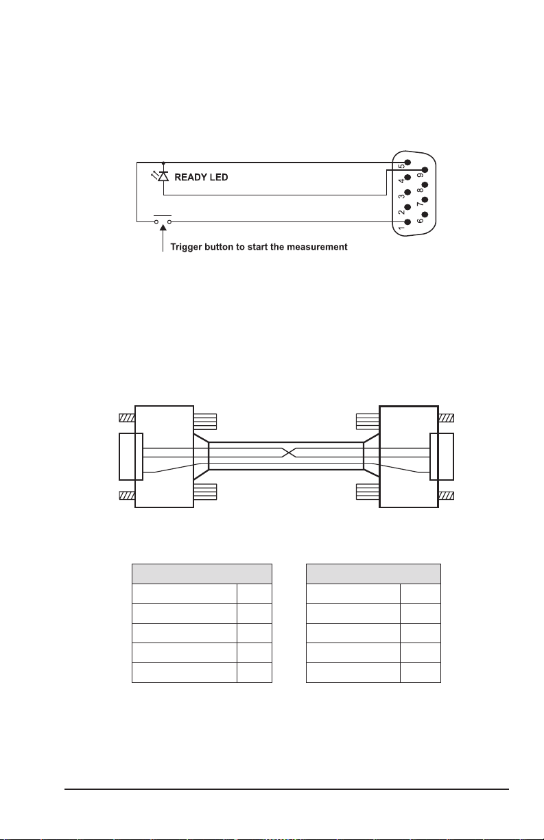
5.3 Cables and Printers Used with the Interface Port
The DB9 interface port can be used to trigger remote measurements
(“TRIG”). Wiring for remote triggering of a test is detailed in Figure 5-2.
The “READY” LED indicates that a measurement can be made.
Figure 5-2
The DB9 interface port can be used for RS-232 communication with a PC,
terminal or a printer. The main connection pins used are detailed in Figures
5-3 and 5-4 respectively.
Connection to a PC or Terminal:
2
3
5
Male Connector Female Connector
Printer end Printer end
Micro-Ohmmeter Model 6250
Figure 5-3
Pin 6250 end
R
x
T
x
2 3 T
3 2 R
Gnd 5 5 Gnd
2
3
5
x
x
43
Page 46

For a Direct Printer Connection:
2
3
8
5
Figure 5-4
Male Connector Female Connector
Printer end Printer end
Pin Pin
R
x
T
x
2 3 T
3 2 R
Gnd 5 5 Gnd
CTS 8 8 CTS
2
3
8
5
x
x
44
Micro-Ohmmeter Model 6250
Page 47

CHAPTER 6
DATAVIEW® SOFTWARE
6.1 Installing DataView
®
DO NOT CONNECT THE INSTRUMENT TO THE PC BEFORE INSTALLING
THE SOFTWARE AND DRIVERS.
NOTE: When installing, the user must have Administrative access
rights during the installation. The users access rights can be changed
after the installation is complete.
DataView® must be reinstalled for each user in a multi-user system.
USB Flash Drive Install
1. Insert the USB stick into an available USB port (wait for driver to be
installed).
2. If Autorun is enabled then an AutoPlay window should appear as
shown.
Micro-Ohmmeter Model 6250
45
Page 48
NOTE: If Autorun is disabled, it will be necessary to open Windows
Explorer, then locate and open the USB stick drive labeled “DataView” to
view the files on the drive.
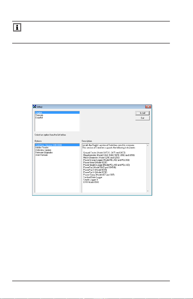
3. In the AutoPlay window, select Open Folder to view Files.
Double-click on Setup.exe from the opened folder view to launch the
4.
DataView setup program.
5. A Set-up window, similar to the one below, will appear.
Figure 6-1
There are several dierent options to choose from. Some options(*) require
an internet connection.
46
Micro-Ohmmeter Model 6250
Page 49

• DataView, Version x.xx.xxxx - Installs DataView® onto the PC.
• *Adobe Reader - Links to the Adobe® website to download the
most recent version of Adobe® Reader to the computer. Adobe®
Reader is required for viewing PDF documents supplied with
DataView®.
• *DataView Updates - Links to the online DataView® software
updates to check for new software version releases.
• *Firmware Upgrades - Links to the online rmware updates to
check for new rmware version releases.
• Documents - Shows a list of instrument related documents
that you can view. Adobe® Reader is required for viewing PDF
documents supplied with DataView®.
6. DataView, Version x.xx.xxxx option should be selected by default.
Select the desired language and then click on Install.
7. The Installation Wizard window will appear. Click Next.
8.
To proceed, accept the terms of the license agreement and click Next.
9. In the Customer Information window, enter a Name and Company,
then click Next.
10.
In the Setup Type window that appears, select the “Complete” radio
button option, then click Next.
11. In the Select Features window that appears, select the instrument’s
control panel that you want to install, then click Next.
NOTE: The PDF-XChange option must be selected to be able to generate
PDF reports from within DataView®.
Micro-Ohmmeter Model 6250
47
Page 50

Figure 6-2
12. In the Ready to Install the Program window, click on Install.
13. If the instrument selected for installation requires the use of a USB
port, a warning box will appear, similar to Figure 6-3. Click OK.
Figure 6-3
NOTE: The installation of the drivers may take a few moments. Windows
may even indicate that it is not responding, however it is running. Please
wait for it to finish.
14. When the drivers are nished installing, the Installation Successful
dialog box will appear. Click on OK.
15. Next, the Installation Wizard Complete window will appear. Click on
Finish.
16. A Question dialog box appears next. Click Yes to read the procedure
for connecting the instrument to the USB port on the computer.
48
Micro-Ohmmeter Model 6250
Page 51

NOTE: The Set-up window remains open. You may now select another
option to download (e.g. Adobe® Reader), or close the window.
17. Restart your computer, then connect the instrument to the USB port
on the computer.
18. Once connected, the Found New Hardware dialog box will appear.
Windows will complete the driver installation process automatically.
The DataView folder containing shortcuts for DataView® and each control
panel selected during installation has
been added to your desktop.
NOTE: If you connected your instrument to the computer before installing
the software and drivers, you may need to use the Add/Remove Hard-
ware utility to remove the instrument driver before repeating the process.
6.2 Connecting the Instrument to your Computer
The Model 6250 is supplied with a serial cable (Cat. #2119.45) necessary
for connecting the instrument to the computer.
To connect the instrument to your computer, connect one end of the serial
cable to the communications port on the Model 6250 and the other end to
the port on the computer.
6.3 Establishing Communication to the Instrument
1.
Double-click the Micro-ohmmeter Icon in the DataView folder
that was created during software installation, located on the
desktop. This opens the Micro-ohmmeter Control Panel.
2. From the main menu, go to Instrument > Connect to open the
Connection dialog box.
Figure 6-4
Micro-Ohmmeter Model 6250
49
Page 52

3. Make sure the Communication port and rate match the port that the
serial cable is plugged into and the baud rate the instrument is congured to (see §4.2.2).
4. From the Instrument model drop-down menu, select the correct model,
if necessary.
5. Once the proper parameters have been specied, click OK.
6.4 Configuring the Instrument
1. Establish a connection to the instrument (see § 6.3).
2. Go to Instrument > Congure from the main menu to open the Conguration Panel dialog box.
Figure 6-5
This dialog box allows you to congure the Measurement Type, Temperature Correction, Ambient Temperature, Metal type, Lock programming and
enable/set the two Alarm thresholds.
Conguration Panel Options:
• Measurement Type: Species the type of measurement that will
be performed.
• Temperature Correction: Enables and disables compensation
of resistance measurements based on temperature.
• Ambient Temperature: Allows User to enter the ambient
temperature or use the PT100 temperature probe to measure the
50
Micro-Ohmmeter Model 6250
Page 53

ambient temperature. Used in conjunction with the temperature
correction option.
• Metal Type: Allows the selection of the most common metal
types, as well as user selectable type. Used in conjunction with
the temperature correction option.
• Alarm 1 and 2: Enables and disables alarm number 1 or 2
notication.
• Lock Programming: Disables the ability to change the
conguration of the instrument.
The conguration panel also contains four command buttons:
• Delete Tests: Displays a dialog box which allows the deletion of
selected tests.
• Write to Instrument: Programs the micro-ohmmeter using the
current settings.
• Read from Instrument: Reads the current conguration of the
micro-ohmmeter attached via the communications cable.
• Cancel: Closes the Conguration dialog box and brings up the
Control Panel.
Once all of the elds have been congured, click on the Write to Instrument button to congure the instrument and close the Conguration dialog
box.
Micro-Ohmmeter Model 6250
51
Page 54

6.5 Downloading Stored Tests
1. To download stored tests, go to Instrument > Download.
2. The Select Tests dialog box will appear displaying a list of tests stored
in the instrument.
Figure 6-6
3. Click on the desired test to download (hold the Ctrl key to select
multiple tests), then click the Download button.
To edit the name and other properties of the test, double-click on the
Test’s name on the left side of the control panel.
6.6 Creating a DataView® Report
1. Download a stored test (see § 6.5)
2. Select the test to create the DataView® report for.
3. Go to File > Create DataView Report from the main menu.
52
Micro-Ohmmeter Model 6250
Page 55

6.7 Exporting the Report to a Spreadsheet or PDF File
Exporting to a PDF le:
1. With a report open in DataView®, go to File > Print Worksheet.
2. In the Print dialog box that appears, make sure that PDF-XChange
3.0 is selected from the drop-down menu, then click OK.
3. When the PDF is complete, the Save As dialog box will appear.
Choose a location to save it to and click Save.
Exporting to a Spreadsheet:
1. With a report open in DataView®, go to File > Export to Spreadsheet.
2. Click the Export measurements button. The Export Step 1 dialog
box will appear.
3. Click the Browse button to open the Save As dialog box.
4. Choose a location to save your le from the Save in drop-down
menu at the top. Then, type a le name in the File name eld at the
bottom and click Save.
NOTE: For additional help on using the software, use DataView’s “Help”
Menu, which is located on the menu bar.
Micro-Ohmmeter Model 6250
53
Page 56

CHAPTER 7
TROUBLESHOOTING
The Model 6250 incorporates internal diagnostics and will inform the operator of any condition needing attention through the use of error messages.
The available messages are described here.
7.1 Fault Indicators
Err 1 Low battery level
Err 2 Internal problem
Err 3 Unable to measure battery
Err 4 Unable to measure temperature
Err 5 Internal temperature too high - let the instrument cool down
Err 6 Unable to establish current measurement
Err 7 Measurement out of range
Err 8 Internal problem
Err 9 Measurement cycle stopped
Err 10 Temperature sensor incorrectly connected or missing
Err 11 Current leads incorrectly connected
Err 12 Voltage leads incorrectly connected or measured resistance
too high
Err 13 Residual voltage too high
Err 21 Adjustment out of range
Err 22 Measured value out of range
Err 23 Entry out of range
Err 24 Unable to write to memory
Err 25 Unable to read memory
Err 26 Memory full
Err 27 Memory empty; no data available
Err 28 Memory check problem
Err 29 Object or test number incorrect
WARNING: If error message 2, 3, 4, or 8 appears, the instrument must be
sent to a qualified organization for repair. See the Repair and Calibration
section for return instructions.
54
Micro-Ohmmeter Model 6250
Page 57

CHAPTER 8
APPLICATION EXAMPLES
The proper procedures for using the Model 6250 in some specic applications are outlined throughout this section.
8.1 Measuring Winding Resistance of Motors
and Transformers
WARNING: Prior to and after testing a transformer winding, the energy
stored in the magnetic field must be dissipated by shorting the transformer terminals. For additional safety, the transformer terminals should
be jumpered together before the instrument is disconnected.
One terminal of the sample should be grounded for safety!
Make connections to the transformer as shown in Figure 8-1. On larger
transformers, the measurement stabilization time will increase.
Micro-Ohmmeter Model 6250
Figure 8-1
55
Page 58

8.2 Measuring Resistance on Electric Motors
For this test, Kelvin probes should be used (Figure 8-2). Make contact
with each segment on the motor commutator. Allow approximately two
seconds for the display to stabilize.
Figure 8-2
8.3 Battery Strap Measurements
Proper battery strap resistance measurements will help ensure proper
voltage output. The resistance on battery strap connections should be
measured using the Kelvin probes (see Figure 8-3). Measurements must
be made with the system power turned o.
The average resistance of all the intercell connections should be
determined by totaling the individual resistances and dividing by the
number of connectors. Each individual cell resistance should not exceed
the average by more than 10%. See the manufacturer’s specications for
typical resistance values.
Battery Battery
Figure 8-3
56
Micro-Ohmmeter Model 6250
Page 59

CHAPTER 9
MAINTENANCE
Use only factory specied replacement parts. AEMC® will not be held
responsible for any accident, incident, or malfunction following a repair
done other than by its service center or by an approved repair center.
9.1 Warning
• To avoid electrical shock, do not attempt to perform any servicing
unless you are qualied to do so.
• Do not perform any service while the micro-ohmmeter is on any
circuit.
• To avoid electrical shock and/or damage to the instrument, do not
get water or other foreign agents into the electronic module.
• Make sure the internal battery is fully charged prior to testing. If
the instrument has been left unused for several months, recharge
the battery.
• We recommend recharging the micro-ohmmeter every month to
ensure a full battery charge when used.
• When replacing fuses, install only fuses which are direct replacements.
9.2 Cleaning
WARNING: Disconnect the instrument from any source of electricity.
• If the case needs cleaning, do not use any alcohol or oil based
cleaners. Preferably use soapy water with a damp cloth or
sponge.
• Dry immediately after cleaning. Avoid water penetration into the
electronic module.
• Make sure the micro-ohmmeter and all leads are dry before further use.
Micro-Ohmmeter Model 6250
57
Page 60

9.3 Charging/Recharging the Battery
AC POWER SELECTION
The Model 6250 may be recharged from 90 to 264VAC (45 to 420Hz). The
instrument includes a 110V line cord, which provides the charging voltage
for the rechargeable battery.
CHARGING THE BATTERY
The Model 6250 should be charged to a full charge before using it for the
rst time. Charging to full capacity may take up to 6 hours for a completely
discharged battery
If the battery symbol is ashing, the battery needs to be recharged.
The battery will charge in both the ON and OFF mode.
• In the ON mode, the charging indicators will show on the display.
• In the OFF mode, no display will show during charging.
Connect the Model 6250 to 120VAC using the power cord provided (charg-
ing starts automatically).
NOTE: Testing can not be conducted while charging the batteries. Button
presses are ignored when charging is in process.
CHARGING INDICATORS
• bAt on the small display and CHrg on the main display, signies
fast charging in progress.
• bAt on the small display and CHrg ashing on the main display,
signies slow charging (starts o with fast charge, temperature
conditions permitting).
• bAt on the small display and FULL on the main display, signies
that charging is complete.
If the instrument is turned on and the battery voltage is >5V, then the
normal use of the device is permitted.
58
Micro-Ohmmeter Model 6250
Page 61

9.4 Battery and Fuse Replacement
NOTE: Make sure that no terminals are connected and that the switch is
in the OFF position before opening the front panel.
BATTERY
• Replacing the battery causes data to be lost from the memory.
• The battery should only be replaced by a qualied technician or
sent back to the factory for replacement and standard calibration.
See the Repair and Calibration section for return instructions.
FUSES
• Before replacing the internal batteries or fuses, the front panel
must rst be removed. Use a Phillips Head screwdriver to remove
the four screws from the feet on the bottom of the case.
• Pull out the chassis from the top.
• The two fuses are located on the left side of the chassis.
F1 is located near the C1 and P1 terminals.
F2 is located directly below on the bottom power supply board
assembly.
• Fuse F1, is a 6.3x32 mm, fast acting, 16A/250V, low internal
resistance, protecting the current source from outside voltages on
energized specimens.
• Fuse F2, is a 5.0x20 mm, fast acting, 2A/250V, protecting the
battery charger power supply board.
Micro-Ohmmeter Model 6250
59
Page 62

Repair and Calibration
To ensure that your instrument meets factory specications, we recommend
that it be scheduled back to our factory Service Center at one-year intervals
for recalibration, or as required by other standards or internal procedures.
For instrument repair and calibration:
You must contact our Service Center for a Customer Service Authorization
Number (CSA#). This will ensure that when your instrument arrives, it will be
tracked and processed promptly. Please write the CSA# on the outside of the
shipping container. If the instrument is returned for calibration, we need to
know if you want a standard calibration, or a calibration traceable to N.I.S.T.
(Includes calibration certicate plus recorded calibration data).
Ship To: Chauvin Arnoux®, Inc. d.b.a. AEMC® Instruments
15 Faraday Drive
Dover, NH 03820 USA
Phone: (800) 945-2362 (Ext. 360)
(603) 749-6434 (Ext. 360)
Fax: (603) 742-2346 or (603) 749-6309
E-mail: repair@aemc.com
(Or contact your authorized distributor)
Costs for repair, standard calibration, and calibration traceable to N.I.S.T. are
available.
NOTE: You must obtain a CSA# before returning any instrument.
Technical and Sales Assistance
If you are experiencing any technical problems, or require any assistance with
the proper operation or application of your instrument, please call, mail, fax or
e-mail our technical support team:
Chauvin Arnoux®, Inc. d.b.a. AEMC® Instruments
200 Foxborough Boulevard
Foxborough, MA 02035 USA
Phone: (800) 343-1391
(508) 698-2115
Fax: (508) 698-2118
E-mail: techsupport@aemc.com
www.aemc.com
NOTE: Do not ship Instruments to our Foxborough, MA address.
60
Micro-Ohmmeter Model 6250
Page 63

Limited Warranty
The Micro-ohmmeter Model 6250 is warranted to the owner for a period of two
years
from the date of original purchase against defects in manufacture.
This limited warranty is given by AEMC® Instruments, not by the distributor
from whom it was purchased. This warranty is void if the unit has been
tampered with, abused or if the defect is related to service not performed by
AEMC® Instruments.
Full warranty coverage and product registration is available on our
website at www.aemc.com/warranty.html.
Please print the online Warranty Coverage Information for your records.
What AEMC® Instruments will do:
If a malfunction occurs within the warranty period, you may return the instrument
to us for repair, provided we have your warranty registration information on
file or a proof of purchase. AEMC® Instruments will, at its option, repair or
replace the faulty material.
REGISTER ONLINE AT: www.aemc.com
Warranty Repairs
What you must do to return an Instrument for Warranty Repair:
First, request a Customer Service Authorization Number (CSA#) by phone
or by fax from our Service Department (see address below), then return the
instrument along with the signed CSA Form. Please write the CSA# on the
outside of the shipping container. Return the instrument, postage or shipment
pre-paid to:
Ship To:
Caution: To protect yourself against in-transit loss, we recommend you insure
your returned material.
NOTE: You must obtain a CSA# before returning any instrument.
Chauvin Arnoux®, Inc. d.b.a. AEMC® Instruments
15 Faraday Drive • Dover, NH 03820 USA
Phone: (800) 945-2362 (Ext. 360)
(603) 749-6434 (Ext. 360)
Fax: (603) 742-2346 or (603) 749-6309
E-mail: repair@aemc.com
Page 64

09/17
99-MAN 100288 v25
15 Faraday Drive • Dover, NH 03820 USA • Phone: (603) 749-6434 • Fax: (603) 742-2346
Chauvin Arnoux®, Inc. d.b.a. AEMC® Instruments
www.aemc.com
 Loading...