

Page 1
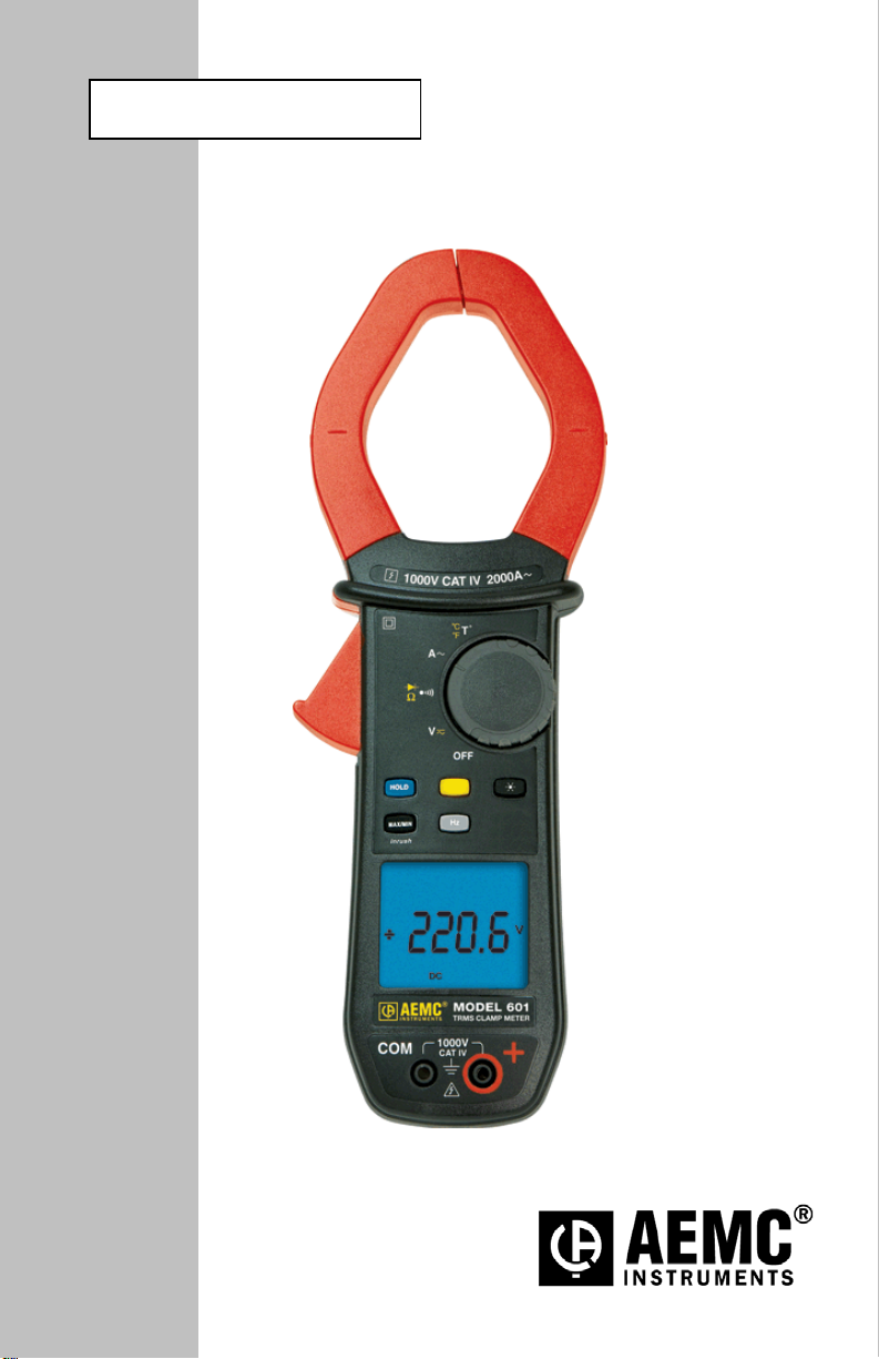
User Manual
ENGLISH
CLAMP-ON METER
601
Page 2
2
Page 3
CONTENTS
RECEIVING YOUR SHIPMENT ........................................................................... 7
ORDERING INFORMATION ................................................................................ 7
1 PRESENTATION .......................................................................................... 8
1.1 THE ROTARY SWITCH ................................................................................. 9
1.2 THE FUNCTION BUTTONS ........................................................................ 10
1.3 THE DISPLAY .............................................................................................. 11
1.3.1 Display Symbols ........................................................................... 11
1.3.2 Measurement Capacity Exceeded (OL) ........................................ 12
1.4 THE TERMINALS ........................................................................................ 12
2 THE BUTTONS ........................................................................................... 13
2.1
2.2 (YELLOW) BUTTON (SECOND FUNCTION) ............................................ 14
2.3 BUTTON ............................................................................................. 14
2.4 BUTTON ........................................................................................... 15
2.4.1 Normal Mode ................................................................................ 15
2.4.2 The MAX/MIN Mode + Activation of the HOL D Mode ................... 16
2.4.3 Access to the True Inrush® Mode ( set to ) .................. 16
2.5
2.5.1 Normal Mode ................................................................................ 17
2.5.2 The Hz Function + Activation of the HOLD Mode ......................... 17
3 USE ............................................................................................................. 18
3.1 INSTALLING THE BATTERIES ................................................................... 18
3.2 TURNING THE CLAMP-ON METER ON .................................................... 18
3.3 TURNING THE CLAMP-ON METER OFF .................................................. 18
3.4 CONFIGURATION ....................................................................................... 19
3.4.1 Configuring the Maximum Resistance for Continuity .................... 19
3.4.2 Auto Power OFF ........................................................................... 19
3.4.3 Configuring the Threshold for True InRush® Measurement .......... 19
3.4.4 Changing the Default Temperature U nit ....................................... 20
3.4.5 Default Configuration .................................................................... 21
3.5 VOLTAGE MEASUREMENT (V) ................................................................. 21
3.6 CONTINUITY TEST ............................................................................... 22
3.6.1 Lead Resistance Compensation ................................................... 22
3.7 RESISTANCE MEASUREMENT Ω ............................................................. 23
3.8 DIODE TEST ......................................................................................... 23
3.9 CURRENT MEASUREMENT (A) ................................................................ 24
3.9.1 AC Measurement .......................................................................... 24
3.10 STARTING CURRENT OR OVERCURRENT (True InRush®)
BUTTON ............................................................................................... 13
BUTTON ............................................................................................. 17
MEASUREMENT ......................................................................................... 25
3
Page 4

FREQUENCY MEASUREMENT (HZ) ......................................................... 25
3.11
3.11.1 Frequency Measurement (V) ........................................................ 25
3.11.2 Frequency Measurement (A) ........................................................ 26
3.12 TEMPERATURE MEASUREMENT ............................................................ 27
3.12.1 Measurement without External Sensor ......................................... 27
3.12.2 Measurement with External Sensor .............................................. 27
4 SPECIFICATIONS ...................................................................................... 28
4.1 REFERENCE CONDITIONS ....................................................................... 28
4.2 SPECIFICATIONS UNDER THE REFERENCE CONDITIONS ................. 28
4.2.1 DC Voltage Measurement ............................................................. 28
4.2.2 AC Voltage Measurement ............................................................. 29
4.2.3 AC Current Measurement ............................................................. 29
4.2.4 True Inrush® Measurement ........................................................... 30
4.2.5 Continuity Measurement ............................................................... 30
4.2.6 Resistance Measurement ............................................................. 30
4.2.7 Diode test ...................................................................................... 31
4.2.8 Frequency Measurements ............................................................ 31
4.2.9 Temperature Measurement ........................................................... 32
4.3 ENVIRONMENTAL CONDITIONS .............................................................. 32
4.4 MECHANICAL SPECIFICATIONS .............................................................. 33
4.5 POWER SUPPLY ........................................................................................ 33
4.6 COMPLIANCE WITH INTERNATIONAL STANDARDS ............................. 33
4.7 ENVIRONMENTAL VARIATIONS ............................................................... 34
5 MAINTENANCE .......................................................................................... 35
5.1 WARNING .................................................................................................... 35
5.2 CLEANING ................................................................................................... 35
5.3 REPLACEMENT OF THE BATTERIES ...................................................... 35
6 REP AIR AND CALI BRATION .................................................................... 36
7 TECHNICAL AND SALES ASSISTANCE .................................................. 36
8 LIMITED WARRANTY ................................................................................ 37
9 WARRANTY REPAIRS .............................................................................. 37
4
Page 5

tes a WARNING and that the operator
must refer to the user manual for instructions before operating the instrument
Risk of electric shock. The voltage at the parts marked with this symbol may
Refers to a type A current sensor. This symbol signifies that application
In the European Union, this product is subject to a separate collection system
for recycling electrical and electronic components In accordance wit h directive
Thank you for purchasing a Model 601 Clamp-on Meter.
For best results from your instrument and for your safety, read the enclosed
operating instructions carefully an d comply with the precautions for use. These
products must be only used by qualified and trained users.
Meanings of the symbols used on the device
CAUTION - Risk of Danger! Indica
in all cases where this symbol is marked.
be dangerous.
around and removal from HAZARDOUS LIVE conductors is permitted.
1.5 V battery
The CE marking indicates compliance with European directives
Double insulation or reinforced insulation
WEEE 2002/96/EC
AC – Alternating current
AC and DC – Alternating and direct current
Ground/Earth
5
Page 6

PRECAUTIONS FOR USE
This device complies with safety standards IEC-61010-1 and 61010-2-032 for voltages of
1000V in category IV at an altitude of less than 2000m, indoors, with a degree of pollution
not exceeding 2.
These safety instructions are intended to ensure the safety of persons and proper operation
of the device.
The operator and/or the responsible authority must carefully read and clearly
understand the various precautions to be taken in use.
If this instrument is used other than as specified, the protecti on it provides may be
compromised, thereby endangering you.
Do not use the instrument in an explosive atmosphere or in the presence of flammable
gases or fumes.
Do not use the instrument on networks of which the voltage or category exceeds those
mentioned.
Do not exceed the rated maximum voltages and currents between terminals or with
respect to earth.
Do not use the instrument if it appears to be damaged, inc omplete, or not properly
closed.
Before each use, check the condition of the insulation on the leads, housing, and
accessories. Any element of which the insulation is deteriorated (even partiall y) must
be set aside for repair or scrapped.
Use leads and accessories rated for voltages and categories at least equal to those of
the instrument. If not, an accessory of a lower category lowers the category of the
combined Clamp + accessory to that of the accessory.
Observe the environmental conditions of use.
Do not modify the instrument and onl y use factory replacement parts. Repairs and
adjustments must be done by approved qualified personnel.
Replace the batteries as soon as the symbol app ears on the display of the unit.
Disconnect all leads before opening the battery compartment cover.
Use personal protective equipment when conditions require.
Keep your hands away from the unused terminals of the instrument.
When handling the test probes, alligator c lips, and clamp ammeters, keep your fingers
behind the physical guard.
As a safety measure, and to avoid repeated overloads on the inputs of the device,
configuration operations should only be performed when the device is disconnected
from all dangerous voltages.
6
Page 7

MEASUREMENT CATEGORIES
Definitions of the measurement cat egories :
CAT II: Circuits directly connected to the low-voltage installation.
Example: power supply to household electrical appliances and portable tools.
CAT III: Power supply circuits in the installation of the building.
Example: distribution panel, circuit-breakers, fixed industrial mac hines or
devices.
CAT IV: Circuits suppl ying the low-voltage installation of t he building.
Example: power lines, meters, and protection devices.
RECEIVING YOUR SHIPMENT
Upon receiving your shipm ent, make sure that the content s are consistent with the
packing list. Notify your d istributor of any missing it ems. If the equipm ent appears
to be damaged, file a cla im immediat ely with t he carrier a nd notif y your distrib utor
at once, giving a detailed description of any damage. S ave the damag ed packing
container to substantiate your claim.
ORDERING INFORMATION
Clamp-on Meter Model 601 .......................................................... Cat. #2139.30
Includes set of 2 color-coded silicone insulated test leads , test probes and alligator clips,
K-thermocouple with 4mm integrated adapter, soft carrying case, 4x1.5V AA batteries and
user manual.
Replacement Parts:
K-thermocouple with 4mm Integrated Adapter ................................................. Cat. #2139.71
Soft Carrying Case ........................................................................................... Cat. #2139.72
Set of 2 Color-coded Silicone Test Leads, Test Probes & Alligator Clips ........ Cat. #2152.05
7
Page 8
1
3
2
7
ring marks
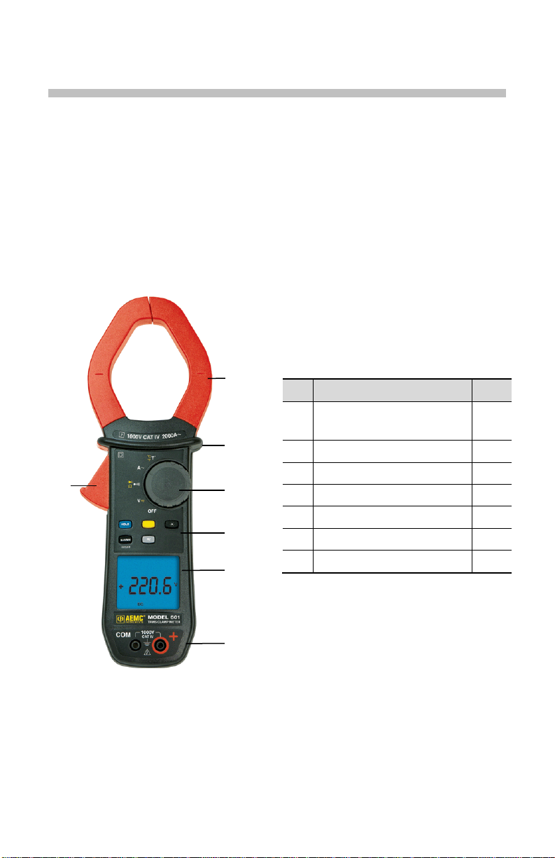
1 PRESENTATION
The Clamp-on Meter Model 601 is a professional electrical measuri ng instrument
that combines the following funct i ons :
Current measurement
Measurement of True InRush
Voltage measurement
Frequency measurement
Continuity test with buzzer
Resistance measurement
Diode test
Temperature measurement
®
current / overcurrent
Item
1
2 Physical Guard 3 Rotary Function Switch 1.1
4 Function Buttons 2
5 Backlit Display 1.3
4
5
6 Input Terminals 1.4
7 Trigger -
Designation See §
Jaws with cente
(see connection principles)
3.5 to
3.12
6
Figure 1: Clamp-on Meter Model 601
8
Page 9
1
2 3 4
5
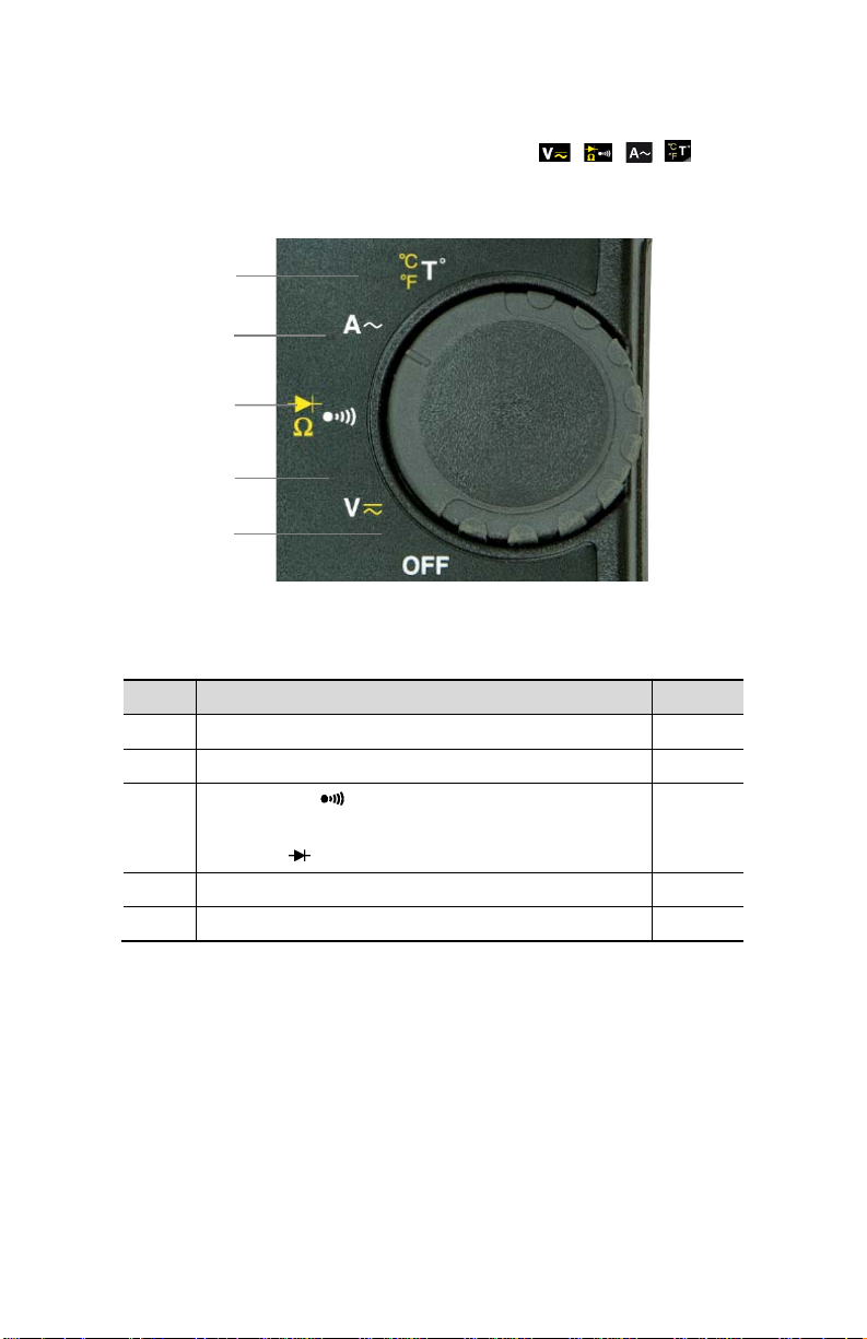
1.1 THE ROTARY SWITCH
The rotary switch has five positions. T o access the , , , , functions,
set the switch to the desired function. The functions are described in the table
below.
Figure 2: The Function Rotary Switch
Item Function See §
1 OFF mode – Turns the clamp-on meter off 3.3
2 AC, DC voltage measurement (V) 3.5
3 Continuity test
Resistance measurement Ω
Diode test
4 AC current measurement (A) 3.9
5 Temperature measurement (°C/°F) 3.12
3.6
3.7
3.8
9
Page 10
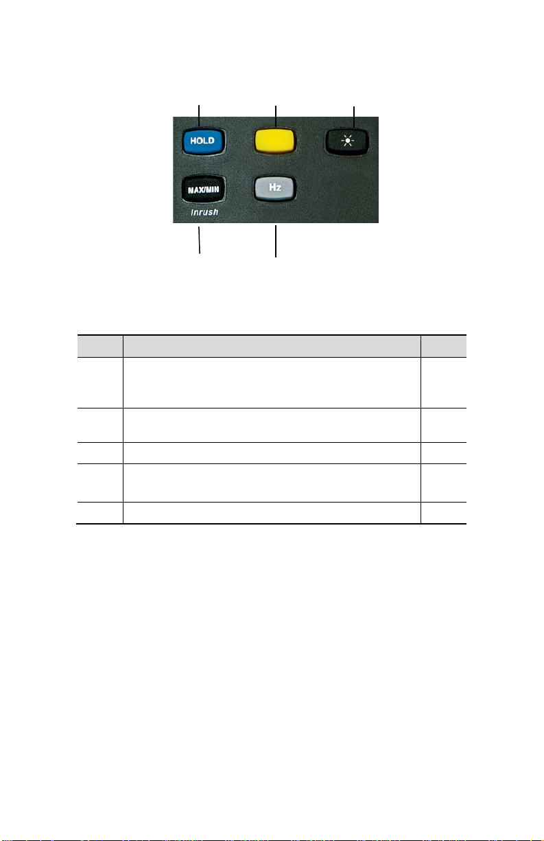
1.2 THE FUNCTION BUTTONS
1 2 3
4 5
Figure 3: The Function Buttons
Item Function See §
1 Holds the last value on the display
Lead resistance compensation in the continuity and
ohmmeter functions
2 Selects the type of measurement and configuration
functions (AC, DC)
3 Enables/disables display backlighting 2.3
4 Enables/disables the MAX/MIN mode
Enables/disables the True InRush
5 Performs Frequency measurements (Hz) 2.5
®
mode
2.1
3.6.1
2.2
2.4
10
Page 11
1
4
6
5
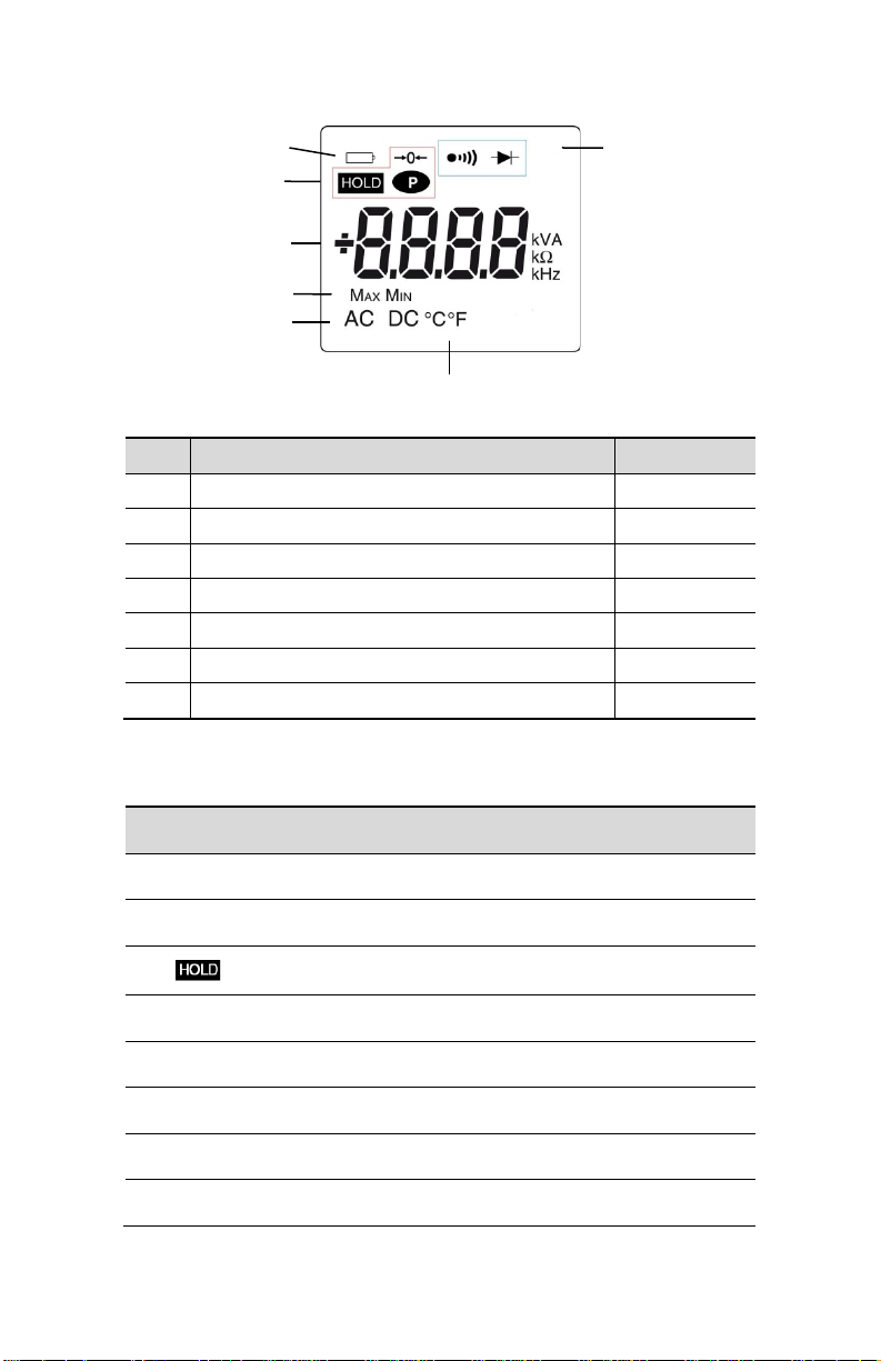
THE DISPLAY
2
3
7
Figure 4: The Display
Item Function See §
1 Mode selection display 2
2 Display of the measurement value and unit 3.5 to 3.12
3 Display of the MAX/MIN modes 2.4
4 Type of measurement (AC or DC) 2.2
5 Selected resistance measurement display 1.1
6 Low battery indication 5.3
7 Temperature unit display 3.4.4
1.2.1 Display Symbols
Symbol Designation
AC Alternating current or voltage
DC Direct current or voltage
Max Maximum DC or RMS value
Min Minimum DC or RMS value
V Volt
Hz Hertz
A Ampere
Storage of the values and display hold
11
Page 12
Ω
°C/°F Temperature unit Celsius or Fahrenheit
Ohm
m Milli- prefix
k Kilo- prefix
Lead resistance compensation
Continuity test
Diode test
Auto Power Off disabled
Low battery indicator
1.2.2 Measurement Capacity Exceeded (OL)
The OL (Over Load) symbol is displayed when the display capacity is exceeded.
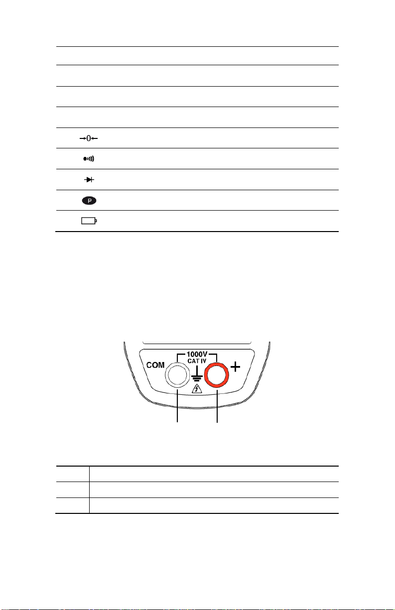
1.3 THE TERMINALS
The terminals are used as follows:
1 2
Figure 5: The Terminals
Item Function
1
COM (Black) Input Terminal Jack
2 + Positive (Red) Input Terminal Jack
12
Page 13
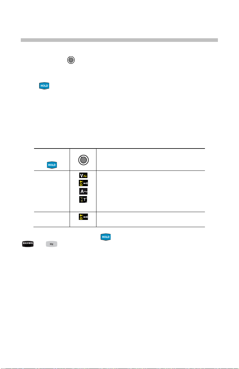
2 THE BUTTONS
The buttons respond differently to short, long, and sustained presses.
In this section, the icon represents the possible positions of the switch for the
button’s functionality.
2.1
BUTTON
This button is used to:
Store and look up the last values acquired specif ic to each function (V, A,
Ω, T°) according to the specific modes previously activated (MAX/MIN, Hz).
The present display is then mainta ined while the detection and acquisition
of new values continues.
Perform automatic lead resistance compensation (see § 3.6.1).
Successive
presses on
long
(> 2 sec)
First press: Holds the display of the last value
displayed
Second press: Returns to normal display mode
(the value of each new measurement is
displayed)
Performs automatic lead resistance
compensation (see 3.6.1)
Function
See § 2.4.2 and § 2.5.2 f or the button functionality in c ombination with the
and buttons.
13
Page 14

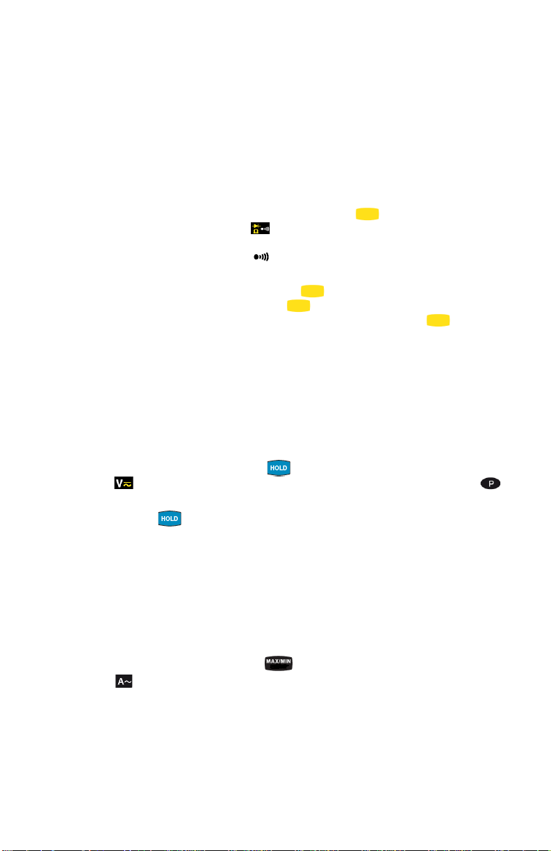
2.2 (YELLOW) BUTTON (SECOND FUNCTION)
This button is used to select the type of m easurement (AC, DC ) and the second
functions marked in yellow next to the r el evant positions of the switch.
It can also be used to modify the default values in the configuration mode
(see § 3.4).
NOTE: This button is invalid in the MAX/MIN and HOLD modes.
Successive
presses on
- Selects AC or DC. Depending on your
choice, the screen displays AC or DC
- Cycles through the continuity , Ω and
diode test modes and returns to the
continuity test
- Selects °C or °F as the temperature unit
Function
2.3 BUTTON
presses on
Successive
- Enables/disables the backlighting of the
display
Function
NOTE: The backlighting is automatically disabled at the end of 2 minutes.
14
Page 15

he MAX and MIN symbols are
If MIN has been selected, MIN
is not possible to exit from the MAX/MIN
mode. The HOLD function must first be
2.4 BUTTON
2.4.1 Normal Mode
This button activates the detection of the MAX and MIN values of the
measurements mad e. Max and Min are the extreme mean values in DC and the
extreme RMS values in AC.
NOTE: In this mode, the Auto Power Off function of the device is automatically
disabled. The symbol is displayed on the screen.
Successive presses on
short
First press: Activates detection of the
MAX/MIN values
Second press: Displays the MAX or MIN
value successively
Third press: Returns to the display of the
present measurement without exiting from
the mode (the values already detected are
not erased)
NOTE: T
both displayed, but only the symbol of the
measurement selected blinks.
Example:
blinks and MAX is lit steadily.
Function
long (> 2 sec)
NOTE : ΔREL function can be used with the functions of the MAX/MIN mode.
- Exits the MAX/MIN mode. The values
previously recorded are then erased.
NOTE: If the HOLD function is activated, it
disabled.
15
Page 16

detected.
2.4.2 The MAX/MIN Mode + Activation of the HOLD Mode
Successive presses on
short
- Displays the MAX/MIN values detected
before the button was pressed.
- When the button is pressed, the last
Function
value is held on the display.
NOTE: The HOLD function does not interrupt the acquisition of new MAX, MIN values
2.4.3 Access to the True Inrush® Mode ( set switch to )
This button allows measurement of the True Inrush® current (starting current, or
overcurrent in steady-state operation).
Successive presses on
long (>2 sec)
- First press: Enters the True InRush
mode
- "Inrh" is displayed for 3s (the
backlighting blinks)
- The triggering threshold is displayed for
5s (the backlighting is steady)
- "------" is displayed and the "A" symbol
Function
®
flashes (backlighting turns off)
- After detection and acquisition, the
InRush current measurement is
displayed, after the calculations stage "--
----" (backlighting off)
NOTE: The A symbol flashes to indicate
"surveillance" of the signal.
- Second press: Exits the True InRush®
mode (return to simple current
measurement)
short (<2 sec)
Note: A short press
is functional only if a True
InRush value has been
- Displays the PEAK+ value of the current
- Displays the PEAK- value of the current
- Displays the RMS True InRush
NOTE: The A, AC and PEAK values flash
during this sequence.
®
current
16
Page 17

2.6
This button is used to display the f requency measurements of a signal.
NOTE: This button is not functional in the DC mode.
BUTTON
2.6.1 Normal Mode
Successive
presses on
Displays:
- The frequency of the signal measured
- The present voltage (V) or current (A)
measurement
Function
2.6.2 The Hz Function + Activation of the HOLD Mode
presses on
Successive
- Holds the last frequency reading
- Successively displays the last held frequency,
then the voltage or the current
- NOTE: Pressing the button a second
time returns to realtime measurement
updates.
Function
17
Page 18

3 USE
3.1 INSTALLING THE BATTERIES
Insert the batteries supplied with the device as follows:
1. Using a screwdriver, unscrew the battery compartment cover (item 1)
from the back of the housing.
2. Insert the 4x1.5V AA batteries supplied (item 2), observing polarities.
3. Close the battery compartment cover and screw it onto the housing.
2
1
Figure 6 : The Battery Compartment
3.2 TURNING THE CLAMP-ON METER ON
• With the rotary switch set in the OFF position, turn the switch to the
desired function. The display lights (al l symbols) for a fe w seconds (see
§1.3), then the screen of the function chosen is displayed.
• The clamp-on met er i s now ready to make measurements.
3.3 TURNING THE CLAMP-ON METER OFF
The clamp-on meter can be turned off in two ways:
• Manually - Turn the switch to the OFF position.
• Automatically - After ten minutes with no activ ity, the i nstru ment will turn
OFF. Thirty (30) seconds before the dev ice is switched off, an audible
signal sounds intermittently. To r e-activate the device, pres s any button
or turn the rotary switch.
18
Page 19
3.4 CONFIGURATION
As a safety measure, and to avoid repeated overloads on the inputs of the
device, configuration operations should only be performed when the device is
disconnected from all dangerous voltages.
3.4.1 Configuring the Maximum Resistance for Continuity
To configure the maximum resist ance allowed for a continuity:
1. With the switch in the OFF position, hold the (yellow) button down
while turning the switch to until the "full scr een" display ends and a
beep is emitted. The display will indicate the value below which the
buzzer is activated and the symbol is displayed. The value stored by
default is 40Ω. The possible values range between 1Ω and 999Ω.
2. To change the threshold, press the (yellow) button. The right-hand
digit flashes; each press on the (yellow) button increm ents it. To
shift to the next digit, apply a long press (>2s) to the (yellow)
button.
When the desired value is displayed, turn the switch to another setting. The
detection threshold chosen is stored and a double beep is emitted.
3.4.2 Auto Power OFF
The Auto Power OFF feature is enabled by default. To disable it, perform the
following:
1. In the OFF position, hold the button down while turning the switch
to until the "full screen" displa y en ds and a b eep i s emit ted. The
symbol is displayed.
2. When the button is released, the device is i n the voltmeter function
in the normal mode.
3. To return to Auto Power OFF , turn the clamp-on meter OFF and then
back ON again.
3.4.3 Configuring the Current Threshold for True InRush® Measurement
To configure the triggering cur rent threshold of the True InRush® measurement:
1. In the OFF position, hold the button down while turning the switch
to until the "full screen" display ends and a beep is emitted. The
display will indicate the perce ntage overshoot to appl y to the measured
current to determine the measurement triggering threshold.
The value stored by default is 10%, representing 110% of the
established current measured. The possible values are 5%, 10%, 20%,
50%, 70%, 100%, 150%, and 200%.
19
Page 20

2. To change the threshold, press the (yellow) button. The value
flashes; each press on the (yellow) button displays the next value.
To record the chosen threshold, apply a long press (>2s) on the
(yellow) button. A confirmation beep is emitted.
When the desired value is displayed, turn the switch to another setting. The
chosen threshold is stored and a double beep is emitted.
NOTE: The starting (InRush) c urr ent me as ur ement tr igger i ng t hres hol d is fi xe d at
1% of the least sensitive range. T his value i s 1% of 99. 99A or 1A. This threshold
is not adjustable.
3.4.4 Changing the Default Temperature Unit
To program the measurement unit, °C or °F:
1. In the OFF position, hold the (yell ow) button down while turning
the switch to until the "full screen" display ends and a beep is
emitted. The display will indicate the currently assigned unit (°C or °F).
The default unit is °C.
2. Pressing the (yellow) button toggles between °C and °F.
When the desired unit is disp layed, turn the switch to another setting. The un it
chosen is stored and a double beep is emitted.
NOTE: Pressing the (yellow) button during an active temperature
measurement will toggle between °C and °F.
20
Page 21

3.4.5 Default Configuration
To reset the clamp-on meter to its default parameters (factory configuration):
1. In the OFF position, hold the (yellow) button down while turning the
switch to , until the "full screen" display ends and a beep is emit ted.
The "rSt" symbol is displayed.
2. After 2 s, the clamp-on meter emits a doubl e beep, then all of the digital
symbols of the screen are displayed until the (yellow) button is
released. The default paramet ers are then restored:
• Continuity detection threshold = 40Ω
• True InRush triggering threshold = 10%
• Temperature measurement unit = °C
• Adapter functio n scale factor = 10
3.5 VOLTAGE MEASUREMENT (V)
To measure voltage, proceed as follows:
1. Set the switch to .
2. Connect the black lead to the COM terminal and the red lea d to the "+"
terminal.
3. Connect the test probes or the alligator clips to the circuit to be
measured. The device selects AC or DC automatically according to
which measured value is lar ger. The AC or DC symbol displays blinking
in auto detect mode.
To select AC or DC manually, press the (yellow) button to toggle between
them. The symbol corresponding to the choice will then display.
The measured value is displayed on the screen.
21
Page 22

3.6 CONTINUITY TEST
Warning: Before performing the test, make sure that the circuit is off and all
capacitors have been discharged.
1. Set the switch to ; the symbol is displayed.
2. Connect the black lead to the COM terminal and the red lead to the "+"
terminal.
3. Connect the test pr obes or the allig ator clips to the circuit or component
to be measured.
An audible signal is emitted if there is continuity (resistance value is below the
maximum threshold, see § 3.4.1) and the measured value is displayed on the
screen.
3.6.1 Lead Resistance Compensation
Warning: Before the compensation is executed, the MA X/MIN and HO LD m odes
must be de-activated.
To perform automatic compensation of the test lead resistance, proceed as
follows:
1. Short-circuit the leads connected to the meter.
2. Hold the button down until the display unit indicates the lowest
value. The device measures the resist ance of the leads.
3. Release the button. The correction and the symbol are
displayed. The value displayed is stored.
NOTE: The correction value is stored only if it is ≤ 2Ω.
Above 2Ω, the value displayed blink s and is not stored.
22
Page 23

3.7 RESISTANCE MEASUREMENT Ω
Warning: Before making a resistance measureme nt, mak e sure that the ci rcuit is
off and all capacitors have been disc harged.
1. Set the switch to and press t he (yellow) button. T he Ω symbol
is displayed.
2. Connect the black lead to the COM terminal and the red lead to the "+"
terminal.
3. Connect the test pr obes or the alligator clips to the circuit o r component
to be measured.
The measured value is displayed on the screen.
NOTE: To measure low resistance values, first perform lead resistance
compensation (see § 3.6.1).
3.8 DIODE TEST
Warning: Before perf orming the diode test, make sure that t he circuit is off and
all capacitors have been discharged.
1. Set the switch to and pr ess the (yellow) bu tton twice. The
symbol is displayed.
2. Connect the black lead to the COM terminal and the red lead to the "+"
terminal.
3. Connect the test probes or the alligator clips to the component to be
tested.
23
Page 24
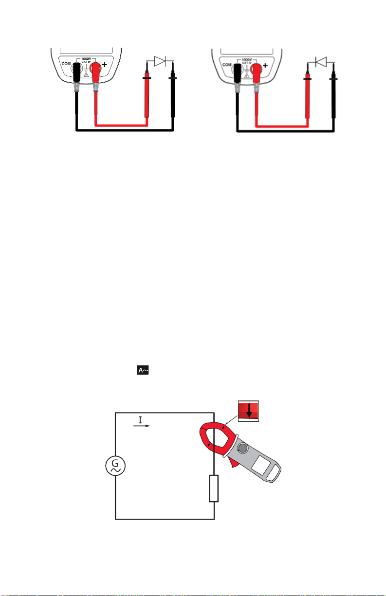
The measured value is displayed on the screen.
4. Reverse the leads on the diode and repeat t he test.
3.9 CURRENT MEASUREMENT (A)
The jaws are opened by pressing the tr igger on t he body of the meter. The arro w
on the jaws of the clamp-on meter (see the diagram below) should point in t he
presumed direction of current flow, from the generator to the load. M ake sure that
the jaws have closed correctly after clamping around the conductor.
NOTE: The measurement results are optim al when the conductor is centered in
the jaws (aligned with the centering marks).
The device selects AC or DC automat ic all y a cc ordi ng to which measured value is
larger. The AC or DC symbol displays blinking in auto detect mode.
NOTE: The Model 601 does not measure DC current.
3.9.1 AC Measurement
For an AC current measurement, proceed as follows:
1. Set the switch to .
2. Clamp the jaws around the conductor to be measured.
The measured value is displayed on the screen.
24
Page 25

3.10 STARTING CURRENT OR OVERCURRENT (True Inrush®) MEASUREMENT
To measure a starting current or overcurrent, proceed as foll ows:
1. Set the switch to , then clamp t he jaws around the conduc tor to be
measured. Press the
2. Perform a long press on the button. The InRh symbol is
displayed, along with the triggering threshold. The clamp then awaits
detection of the True InRush
symbol flashes.
3. After detection and acquisition for 100 ms, the RMS value of the True-
®
current is displayed. Pressing the
Inrush
PEAK+/PEAK- values subsequently.
(yellow) button to select AC measure ment.
®
current. "------" is displayed and the A
button will display the
4. A long press on the button or a change of function on the rotar y
switch will exit the True InRush
®
mode.
NOTE: The triggering thres hold in A is 10A if the init ial cur rent is zero ( start ing of
installation). For an established current (overload in an installation) see §3.4.3.
3.11 FREQUENCY MEASUREMENT (HZ)
The frequency measurement is avail able in V and A for AC measurements. The
measurement is based on a count of zero crossings (positive-going edges).
3.11.1 Frequency Measurement (V)
To measure the frequency in voltage, proceed as follows:
1. Set the switch to and press the button. The Hz symbol is displayed.
2. Select AC by pressing the (yellow) button until the desired choi ce
is reached.
3. Connect the black lead to the COM terminal and the red lead t o the "+"
terminal.
4. Connect the test probes or the alligator clips to the circuit to be
measured.
25
Page 26

The measured value is displayed on the screen.
3.11.2 Frequency Measurement (A)
1. Set the switch to and press the button. The Hz symbol is
displayed.
2. Clamp the jaws around the conductor to be measured.
The measured value is displayed on the screen.
26
Page 27

3.12 TEMPERATURE MEASUREMENT
3.12.1 Measurement without External Sensor
1. Set the switch to .
The temperature (blinking) displa yed is the internal temperature of t he device. It
will be equal to the ambient temperature after a sufficiently long thermal
stabilization time (at least one hour).
3.12.2 Measurement with External Sensor
The device measures the temperature using a K-thermocouple.
1. Connect the K-thermocouple to the COM and “+” input termi nals of the
device observing the red and black banana plug polarity.
2. Set the switch to .
3. Place the K-thermocouple on the element or environment to be
measured. It must not be at a dangerous vol tage.
The temperature will be displayed on the screen.
To change the unit to either °F or °C, press the (yello w) button.
NOTE:
- If the external sensor i s defective, the temperature displayed blinks.
- If there are lar ge variations of the initial temperature environment of the
meter and the measurement environment, the measurement must be
preceded by a stabilization time.
27
Page 28
Measurement range
0.00 to 99.99V
100.0 to 999.9V
1000V (1)
Specified
measurement range
0.00 to 9.99V
±(1% R +3cts)
Resolution
0.01V
0.1V
1V
Input impedance
10MΩ
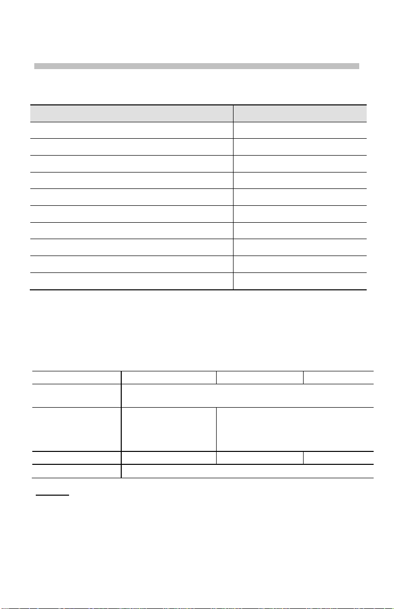
4 SPECIFICATIONS
4.1 REFERENCE CONDITIONS
Quantities of Influence Reference Conditions
Temperature: 23°C ±2°C
Relative humidity: 45% to 75%
Supply voltage: 6.0V ±0.5V
Frequency range of the applied signal: 45 to 65Hz
Sine wave: pure
Peak factor of the applied alter nating signal (A): √2
Position of the conductor in the clamp: centered
Adjacent conductors: none
Alternating magnetic field: none
Electric field: none
4.2 SPECIFICATIONS UNDER THE REFERENCE CONDITIONS
Accuracy is expressed in ± (x% of the reading (R) + y counts (ct)).
4.2.1 DC Voltage Measurement
Accuracy
Note (1) Above 1000V, a repetitive beep indicates that the voltage being
0 to 100% of the measurement range
±(1% R + 10cts)
10.00 to 99.99V
±(1% R +3cts)
measured is greater than the safety voltage for which the device is
guaranteed. The display indicates " OL".
28
Page 29

Measurement
range
1000V RMS
1400V peak (1)
Specified
range (2)
0.15V to 9.99V
± (1% R +3cts)
Resolution
0.01V
0.1V
1V
Input impedance
10MΩ
Measurement
range
Specified
range (2)
1000 to 1500A
± (2% R +5cts)
Resolution
0.01A
0.1A
1A
4.2.2 AC Voltage Measurement
0.15 to 99.99V 100.0 to 999.9V
measurement
Accuracy
± (1% R + 10cts)
10.00 to 99.99V
0 to 100% of the measurement range
± (1% R +3cts)
Note (1) Above 1000V (RMS), a repetitive beep indicates that the voltage
being measured is greater than the safety voltage for which the
device is guaranteed. The display indicates "OL".
- Bandwidth in AC = 3 kHz
Note (2) Any value between zero and the min. t hreshold of the measurement
range (0.15V) is forced to "----" on the display.
Specific Specifications in MAX/MIN mode (from 10Hz to 1kHz, and from
0.30V in AC):
• Accuracy: add 1% R to the values of the table above.
• Capture of the extreme: approximately 100ms.
4.2.3 AC Current Measurement
0.15 to 99.99A 100.0 t o 999.9A 1000 to 2000A (1)
measurement
Accuracy ± (1% R + 10cts) ± (1% R +3cts)
Note (1) - The display indicates “OL” above 2000A.
Note (2) Any value between zero and the min. threshold of the measurement
0 to 100% of the measurement range
± (1.5% R +3cts)
1500 to 2000A
- Bandwidth in AC = 1 kHz
range (0.15A) is forced to show “----“ on t he di s play.
Residual current at zero <150mA.
29
Page 30

Measurement range
20 to 2000AAC
Specified measurement range
0 to 100% of the measurement range
Accuracy
± (5% R + 5cts)
Resolution
1A
Measurement range
0.0 to 999.9Ω
Open-circuit voltage
≤ 3.6V
Measurement current
550µA
Accuracy
± (1% R +5cts)
Buzzer triggering threshold
Adjustable from 1 to 999Ω (40Ω is the default)
0.0 to
999.9Ω
1000 to
9999Ω
10.00 to
99.99kΩ
Specified measurement
range
1 to 100% of the
measurement range
0 to 100% of the
measurement range
Accuracy
± (1% R +5cts)
Resolution
0.1Ω
1Ω
10Ω
Open-circuit voltage
≤ 3.6V
Measurement current
550µA
100µA
10µA
Specific Specifications in MAX/MIN mode (from 10Hz to 1kHz, and from
0.30A in AC):
• Accuracy (with zero corrected): add 1% R to the values of the table
above.
• Capture of the extreme: approximately 100ms.
4.2.4 True Inrush® Measurement
Specific Specifications in PEAK mode in True InRush (from 10Hz to 1kHz):
• Accuracy: add ± (1.5% R +0.5A) to the values in the tables above.
• PEAK capture time: 1ms min. to 1.5ms max.
4.2.5 Continuity Measurement
4.2.6 Resistance Measurement
Measurement range (1)
Note (1) Above the maximum display value, the display unit indicates "OL".
The "-" and "+" signs are not displayed.
Specific Specifications in MAX/MIN mode:
• Accuracy: add 1% R to the values of the table above.
• Capture of the extreme: approximately 100ms.
30
Page 31

Measurement range
0.000 to 3.199VDC
Specified measurement range
1 to 100% of the measurement range
Accuracy
± (1% R + 3cts)
Resolution
0.001V
Measurement current
0.55mA
Indication: junction reversed or
open-circuit
"OL" is displayed when the measured
voltage >3.199V
Measurement range (1)
5.0 to 999.9Hz
1000 to 9999Hz
10 to 19.99kHz
1 to 100% of the
range
Accuracy
± (0.4% R + 1ct)
Resolution
0.1Hz
1Hz
10Hz
Measurement range (1)
5.0 to 999.9Hz
Specified measurement range
1 to 100% of the measurement range
Accuracy
± (0.4% R + 1ct)
Resolution
0.1Hz
4.2.7 Diode test
Note : The "-" sign is disabled for the diode test function.
4.2.8 Frequency Measurements
4.2.8.1 Voltage
Specified measurement
range
4.2.8.2 Current
Note (1) In MAX/MIN mode, the operating range is limited to 1kHz.
If the level of the signal is too low (< 10% of the range, or V<10V or
I<10A) or if the frequency is less than 5Hz, the device cannot
determine the frequency and displays "----".
Specific Specifications in MAX/MIN mode (from 10Hz to 1kHz):
• Accuracy: add 1% R to the values of the table above.
• Capture of the extreme: approximately 100ms.
measurement
31
0 to 100% of the
measurement range
Page 32

Function
External temperature
Type of sensor
K-thermocouple
Measurement range
-60.0° to +999.9°C
-76.0° to +1831.8°F
+1000° to +1200°C
+1832° to +2192°F
Specified measurement
range
1 to 100% of the
measurement range
0 to 100% of the
measurement range
Accuracy (1)
1% R ±3°C
1% R ±5.4°F
1% R ±3°C
1% R ±5.4°F
Resolution
0.1°C
0.1°F
1°C
1°F
4.2.9 Temperature Measurement
Note (1) The stated external temperature measure ment accuracy does not t ake
the accuracy of the K-thermocouple into account.
Note 2 Use of the thermal time constant (0.7min/°C):
If there is a sudden variation of the temperatur e of the clamp, by 10° C
for example, the clamp will be at 99% (cnst = 5) of the final
temperature after 0.7min/°Cx10°Cx5 = 35 min (the time constant of the
external sensor must be added to this value).
Specific Specifications in MAX/MIN mode (10Hz to 1kHz):
• Accuracy: add 1% R to the values of the table above.
• Capture of the extreme: approximately 100ms.
4.3 ENVIRONMENTAL CONDITIONS
Conditions Operating Storage
Temperature -4° to +131°F
Relative humidity (RH): ≤90% up to 131°F (55°C) ≤90% up to 158°F (70°C)
(-20° to +55°C)
32
-40° to +158°F
(-40° to +70°C)
Page 33

Polycarbonate
Clamping diameter: 2.36" (60mm)
LCD display unit
Dimension: 1.6 x 1.9" (41 x 48mm)
4.4 MECHANICAL SPECIFICATIONS
Housing:
Jaws:
Screen:
Dimension: 11.65 x 4.37 x 1.61" (296 x 111 x 41mm)
Weight: 1.4 lbs (640g) with batteries
Rigid polycarbonate shell with over -molded elastomer
covering;
Opening: 2.36" (60mm)
Blue backlighting
UL94 V1
4.5 POWER SUPPLY
Batteries: 4x1.5V AA LR6
Battery life: >350 hours (without backlighting)
Auto Power Off After 10 minutes with no switch and/or button
activity
4.6 COMPLIANCE WITH INTERNATIONAL STANDARDS
Compliant with standards IEC-61010-1,
Electric safety:
IEC-61010-2-30, and IEC-61010-2-32:
1000V CAT IV.
Electromagnetic
compatibility:
Mechanical
strength:
Level of protection
of the housing:
Compliant with standard EN-61326-1
Classification: residential environment
Free fall: 2m (in accordance with standard IEC-68-2-32)
Housing: IP54 (per standard IEC-60529)
Jaws: IP40
33
Page 34

Influence
VAC
Hz
V
A
10Hz to 1kHz
400Hz to 2kHz
1% R
4% R
1% R + 1ct
5% R + 1ct
Position of
the conductor
(f≤400Hz)
Adjacent
RMS
Conductor
the clamp
Application of
the clamp
1.4 to 3.5,
1400V peak
4.7 ENVIRONMENTAL VARIATIONS
Condition of
Influence
Range of
Influence
Measurement
Influenced
Typical MAX
Temperature
Humidity 10 to 90% RH
Frequency
in the
jaws
conductor
carrying a
current of
150A
DC or
enclosed by
a voltage on
-4° to +131°F
(-20° to +55°C)
1kHz to 3kHz
10Hz to 400Hz
Any position
on the internal
perimeter of
the jaws
Conductor
touching the
external
perimeter of
the jaws
0 to 500ARMS V
0 to 1000VDC
or RMS
VDC
A
T°C
Ω
V
A
A 2% R 4% R + 1ct
A 40 dB 45 dB
A
(0.2% R +1°C)/10°C
0.1% R/10°C + 2ct
-
0.1% R/10°C
1% R/10°C
0.1% R 0.1% R + 1ct
8% R
1% R
< 1ct
< 1ct
0.1% R/10°C
0.5% R/10°C + 2ct
1.5% R/10°C + 2ct
(0.3% R +2°C)/10°C
0.1% R/10°C + 3ct
9% R + 1ct
1% R + 1ct
3% R + 1ct
1ct
Peak factor
*Note in Temperature: Influenc e s pecified until 1000 A DC
limited
to 1500A peak
A (AC)
V (AC)
34
1% R
1% R
3% R + 1ct
Page 35

5 MAINTENANCE
5.1 WARNING
• Remove the test leads on any input before opening the case.
• Do not operate the clamp-on meter without a battery case cover.
• To avoid electrical shock, do not attempt to perform any servicing
unless you are qualified to do so.
• To avoid electric al shock and/or damage to the instrument, do not get
water or other foreign agents into the probe.
5.2 CLEANING
Disconnect everything connected to the device and set the switch to
•
OFF.
Use a soft clot h moistened with soapy water. Rinse with a damp cloth
•
and dry quickly using a dry cloth or f orced air.
Dry completely before putting bac k into use.
•
5.3 REPLACEMENT OF THE BATTERIES
The symbol indicates that t he batteri es are low. When this symbol appears
on the display unit, the batteries must be replaced. The measurements and
specifications are no longer guaranteed.
To replace the batteries, proceed as f ollows:
1. Disconnect the measurement leads fr om the input terminals.
2. Set the switch to OFF.
3. Using a screwdriver, unscrew the battery compartment cover from the
back of the housing.
4. Remove the used batteries and replace t hem with 4x1.5V AA batteries,
observing the polarities.
5. Close the battery compartment cover and s crew it onto the housing.
35
Page 36

6 REP AIR AND CALIBRA TION
To ensure that your instrument meets factory specifications, we recommend
that it be submitted to our factory Service Center at one-year intervals for
recalibration, or as required by other standards or internal procedures.
For instrument repair and calibration:
You must contact our Service Center for a Customer Service Authorization
number (CSA#). This will ensure that when your instrument arrives, it will be
tracked and processed promptly. Please write the CSA# on the outside of
the shipping container. If the instrument is returned for calibration, we need
to know if you want a standard calibration, or a calibration traceable to
N.I.S.T. (includes calibration certificate plus recorded calibration data).
Chauvin Arnoux
15 Faraday Drive
Dover, NH 03820 USA
Tel: (800) 945-2362 (Ext. 360)
(603) 749-6434 (Ext. 360)
Fax: ( 603) 742-2346 or (603) 749-6309
repair@aemc.com
(Or contact your authorized distributor)
Costs for repair, standard calibration, and calibration traceable to N.I.S.T. are
available.
NOTE: All customers must obtain a CSA# before returning any
instrument.
7 TECHNICAL AND SALES ASSISTANCE
®
, Inc. d.b.a. AEMC® Instruments
If you are experiencing any technical problems, or require any assistance
with the proper operation or application of your instrument, please call, mail,
fax or e-mail our technical support hotline:
Chauvin Arnoux
®
, Inc. d.b.a. AEMC® Instruments
200 Foxborough Boulevard
Foxborough, MA 02035, USA
Phone: (800) 343-1391
(508) 698-2115
Fax: ( 508) 698-2118
techsupport@aemc.com
www.aemc.com
NOTE: Do not ship instruments to our Foxborough, MA address.
36
Page 37

8 LIMITED WARRANTY
The Model 601 is warranted to the owner for a period of three years from
the date of original purchase against defects in manufacture. This limited
warranty is given by AEMC
®
Instruments, not by the distributor from
whom it was purchased. This warranty is void if the unit has been
tampered with, abused or if the defect is related to service not performed
by AEMC
®
Instruments.
Full warranty coverage and product registration is available on our
website at www.aemc.com/warranty.html
.
Please print the online Warranty Coverage Information for your
records.
If a malfunction occurs within the three-year period, you may return the
instrument to us for repair, provided we have your warranty registration
information on file or a proof of purchase. AEMC
option, repair or replace the faulty material.
®
Instruments w ill, at its
REGISTER ONLINE AT: www.aemc.com
9 WARRANTY REPAIRS
What you must do to return an Instrument for Warranty Repair:
First, request a Customer Service Authorization Number (CSA#) by
phone or by fax from our Service Department (see address below), then
return the instrument along with the signed CSA Form. Please write the
CSA# on the outside of the shipping container. Return the instrument,
postage or shipment pre-paid to:
®
Chauvin Arnoux
, Inc. d.b.a. AEMC® Instruments
15 Faraday Drive • Dover, NH 03820 USA
Tel: (800) 945-2362 (Ext. 360)
(603 ) 749-6434 (Ext. 360)
Fax: (603) 742-2346 or (603) 749-6309
repair@aemc.com
Caution: To protect yourself against in-transit loss, we recommend you
insure your returned material.
NOTE: All customers must obtain a CSA# before returning any
instrument.
37
Page 38

NOTES:
38
Page 39

Page 40

Chauvin Arnoux®, Inc. d.b.a AEMC® Instruments
99-MAN 100368 v4 06/13
15 Faraday Drive • Dover, NH 03820 USA
www.aemc.com
 Loading...