


 Loading...
DIGITAL TRANSFORMER |
8510 |
|
|
RATIOMETER (DTR®) |
|
|
|
E N G L I S H User Manual

Statement of Compliance
Chauvin Arnoux®, Inc. d.b.a. AEMC® Instruments certifies that this instrument has been calibrated using standards and instruments traceable to international standards.
We guarantee that at the time of shipping your instrument has met its published specifications.
An NIST traceable certificate may be requested at the time of purchase, or obtained by returning the instrument to our repair and calibration facility, for a nominal charge.
The recommended calibration interval for this instrument is 12 months and begins on the date of receipt by the customer. For recalibration, please use our calibration services. Refer to our repair and calibration section at www.aemc.com.
Serial #: _ ________________________________
Catalog #: 2136.50 Model #: 8510
Please fill in the appropriate date as indicated:
Date Received: __________________________________
Date Calibration Due: ________________________
Chauvin Arnoux®, Inc. d.b.a AEMC® Instruments
www.aemc.com

Table of Contents
1. INTRODUCTION.................................................................................. |
3 |
|
1.1 |
International Electrical Symbols................................................ |
4 |
1.2 |
Definition of Measurement Categories...................................... |
4 |
1.3 |
Receiving Your Shipment.......................................................... |
5 |
1.4 |
Ordering Information................................................................. |
5 |
|
1.4.1 Accessories and Replacement Parts............................ |
5 |
2. PRODUCT FEATURES.......................................................................... |
6 |
|
2.1 |
Description................................................................................ |
6 |
2.2 |
Control Features........................................................................ |
8 |
2.3 |
Cable Identification.................................................................... |
9 |
3. SPECIFICATIONS.............................................................................. |
10 |
||
3.1 |
DTR® 8510 Specifications....................................................... |
10 |
|
3.2 |
Battery Charger Specifications................................................ |
12 |
|
4. DISPLAY FUNCTIONS....................................................................... |
13 |
||
4.1 |
Program Flow.......................................................................... |
13 |
|
4.2 |
Top Level Menu....................................................................... |
13 |
|
4.3 |
Configure Instrument............................................................... |
14 |
|
|
4.3.1 |
Set Clock..................................................................... |
16 |
|
4.3.2 |
Setup Nameplate......................................................... |
17 |
|
4.3.3 |
Select Test Type.......................................................... |
20 |
|
4.3.4 |
Select Test Mode......................................................... |
20 |
|
4.3.5 |
Select Storage Mode................................................... |
21 |
|
4.3.6 |
Select Filter.................................................................. |
22 |
|
4.3.7 |
Erase Memory............................................................. |
23 |
|
4.3.8 |
Select Language......................................................... |
24 |
|
4.3.9 |
Restoring Factory Defaults.......................................... |
25 |
4.4 |
Recall Data.............................................................................. |
26 |
|
Digital Transformer Ratiometer DTR® Model 8510 |
1 |
5. OPERATION..................................................................................... |
|
|
28 |
|
5.1 |
Power Up |
................................................................................. |
28 |
|
5.2 |
Running a ........................................................................Test |
29 |
||
|
5.2.1 |
VT/PT ...................................................................Test |
29 |
|
|
5.2.2 Storing ...............................the Measurement Record |
31 |
||
|
5.2.2.1 ........................................................ |
Manual Mode |
31 |
|
|
5.2.2.2 ............................................................. |
Auto Mode |
32 |
|
|
5.2.3 |
VT/PT .............................................Excitation Current |
32 |
|
|
5.2.4 |
VT/PT ..................................................Continuity Test |
33 |
|
|
5.2.5 |
CT ........................................................................Test |
33 |
|
5.3 |
Tips for Making .........................Precise Ratio Measurements |
35 |
||
5.4 |
Ratio Test .......................................................................- 1:1 |
36 |
||
6. CONNECTIONS................................................................................. |
37 |
|
6.1 |
Connection Diagrams.............................................................. |
37 |
6.2 |
Polyphase Connections........................................................... |
38 |
7. DATAVIEW® SOFTWARE................................................................... |
39 |
|
7.1 |
Installing DataView®................................................................ |
39 |
7.2 |
Opening the Control Panel...................................................... |
43 |
7.3 |
Using the Control Panel.......................................................... |
45 |
7.4 |
Configuring the DTR® 8510..................................................... |
47 |
7.5 |
Running a Test........................................................................ |
49 |
7.6 |
Downloading a Test................................................................. |
50 |
7.7 |
Saving the Measurement Records.......................................... |
51 |
7.8 |
Report Generation................................................................... |
51 |
8. MAINTENANCE................................................................................ |
53 |
|
8.1 |
Charging the Batteries............................................................. |
53 |
8.2 |
Cleaning.................................................................................. |
56 |
APPENDIX: DISPLAY MESSAGES.......................................................... |
57 |
|
Repair and Calibration..................................................................... |
60 |
|
Technical and Sales Assistance...................................................... |
60 |
|
Limited Warranty.............................................................................. |
61 |
|
Warranty Repairs............................................................................. |
61 |
|
2 |
Digital Transformer Ratiometer DTR® Model 8510 |

CHAPTER 1
INTRODUCTION
 WARNING
These safety warnings are provided to ensure the safety of personnel and proper operation of the instrument.
•This instrument is protected from accidental voltages of not more than 50V with respect to earth. The guaranteed level of protection of this equipment may be compromised if used in a manner not specified by the manufacturer.
•Read the instruction manual completely and follow all safety information before attempting to use or service this instrument.
•The Digital Transformer Ratiometer DTR® Model 8510 is designed for use on de-energized (“dead”) transformers only. Make sure the test sample is completely disconnected from AC power and is fully discharged.
•Only qualified personnel should use the DTR® 8510 .
•The DTR® 8510 must not be used in a manner in which any of its components (including test cables) are relied upon to provide protection from electric shock. No high voltage insulation/ protection is provided by any component of the DTR® 8510.
Always make sure the circuit is fully discharged before attaching any test cables.
•Do not touch, adjust, or reposition test cables while the DTR® is conducting a test.
•Use caution on any apparatus: potentially high voltages and currents may be present and pose a shock hazard.
•Safety is the responsibility of the user.
•Only use the charging unit supplied with the instrument to recharge the battery.
•Never open the instrument while it is connected to AC power or when test cables are connected to transformers, equipment, circuits, etc.
Digital Transformer Ratiometer DTR® Model 8510 |
3 |
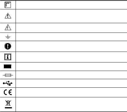
1.1International Electrical Symbols
Signifies that the instrument is protected by double or reinforced insulation.
CAUTION - Risk of Danger! Indicates a WARNING and that the operator must refer to the user manual for instructions before operating the instrument in all cases where this symbol is marked.
Risk of electric shock. The voltage at the parts marked with this symbol may be dangerous.
Ground/Earth
Important instructions to read and understand completely.
Important information to acknowledge.
Battery
Fuse
USB socket
Compliance with the Low Voltage & Electromagnetic Compatibility European directives (73/23/CEE & 89/336/CEE)
In the European Union, this product is subject to a separate collection system for recycling electrical and electronic components In accordance with directive WEEE 2002/96/EC
1.2Definition of Measurement Categories
CAT II: For measurements performed on circuits directly connected to the electrical distribution system. Examples are measurements on household appliances or portable tools.
CAT III: For measurements performed in the building installation at the distribution level such as on hardwired equipment in fixed installation and circuit breakers.
CAT IV: For measurements performed at the primary electrical supply (<1000V) such as on primary overcurrent protection devices, ripple control units, or meters.
4 |
Digital Transformer Ratiometer DTR® Model 8510 |

1.3Receiving Your Shipment
Upon receiving your shipment, make sure that the contents are consistent with the packing list. Notify your distributor of any missing items. If the equipment appears to be damaged, file a claim immediately with the carrier and notify your distributor at once, giving a detailed description of any damage. Save the damaged packing container to substantiate your claim.
1.4 |
Ordering Information |
|
Digital Transformer Ratiometer DTR® Model 8510.......... |
Cat. #2136.50 |
|
Includes NiMH batteries (installed), 115V power cord, set of two 15 ft leads, 10 ft USB cable, external battery charger (90-264VAC 50/60Hz), soft carrying case, DataView® software, and a user manual.
1.4.1 Accessories and Replacement Parts
Fuse - set of 5, 0.5A 250V (5x20mm, Slow Blow)................ |
Cat. #2118.53 |
Fuse - set of 5, 4A 125V (5x20mm, Slow Blow)................... |
Cat. #2118.55 |
Lead - Set of 2, 30 ft............................................................. |
Cat. #2136.76 |
Lead - Replacement Set of 2, 15 ft...................................... |
Cat. #2136.77 |
Battery - Replacement Set of 2, 12V NiMH rechargeable.... |
Cat. #2136.78 |
Replacement Battery Charger.............................................. |
Cat. #2136.79 |
Replacement USB Cable, 10 ft............................................ |
Cat. #2136.80 |
Order Accessories and Replacement Parts Directly Online
Check our Storefront at www.aemc.com for availability
Digital Transformer Ratiometer DTR® Model 8510 |
5 |

CHAPTER 2
PRODUCT FEATURES
2.1Description
The Digital Transformer Ratiometer DTR® Model 8510 is a lightweight, rugged, portable instrument designed for onsite testing of power, potential and current transformers.
Operation of the DTR® 8510 is fully automatic. No user calibration, range selection, hand cranking or tedious balancing is required.
During each test cycle, the DTR® 8510 automatically checks for:
•H/X lead reversal
•Continuity of tested circuits/windings (if configured)
•Short circuit conditions (high current)
Upon completion of a test cycle, the DTR® 8510 displays:
•Turns Ratio: The ratio of the primary to secondary voltage at the transformer terminals due to test excitation
•Excitation Current: The RMS excitation current in the H winding due to test excitation during negligible loading of the associated X winding
•Polarity: Indicates the polarity (phase) of X relative to H
•Deviation: Indicates the deviation from nameplate ratio in %
Turns Ratio, Excitation Current, Polarity and Deviation are useful parameters in diagnosing and predicting a variety of faults that occur in power, potential and current transformers.
6 |
Digital Transformer Ratiometer DTR® Model 8510 |

The DTR® 8510 will display the following messages:
•Incorrect Lead Connections
•H/X Reversal (accidental step-up misconnection)
•Short (excess excitation current)
•Open Circuits
•Circuit Continuity
•Low Battery
In addition, the DTR® 8510 allows the user to store the data in automatic or manual mode after each test eliminating the need to write down the test results. Each measurement record is date and time stamped providing complete test information.
The user can also save Nameplate voltages and compare the results as the data is being gathered. The data can later be downloaded to a PC and analyzed using the DataView® software package which is included with the product.
DataView® allows full control of the instrument.
The DTR® 8510 utilizes an advanced, low-voltage, step-down measurement technique in which the high voltage “H” windings are subjected to test excitation. This results in greater operator safety and the ability to test a much wider array of transformer types and sizes.
Digital Transformer Ratiometer DTR® Model 8510 |
7 |
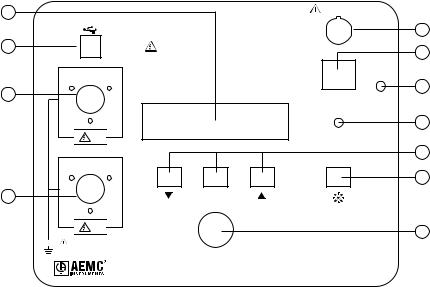
2.2Control Features
1 |
|
USE SPECIFIED |
|
CHARGER ONLY |
|
2 |
|
USE ONLY ON DE-ENERGIZED TRANSFORMERS |
|
|
OFF/ |
|
|
CHARGE |
3 |
|
ON |
|
|
|
|
H |
CONTRAST |
|
|
|
|
|
MEM |
4 |
|
ENTER |
|
|
|
|
X |
|
|
50V CAT IV |
|
5
6
7
8
9
10
11
TEST |
DIGITAL TRANSFORMER RATIOMETER |
|
|
|
DTR® MODEL 8510 |
1.Display: Displays data, status and control features of the instrument.
2.USB Connector: Allows connection to a computer for instrument configuration set-up and status check, downloading of the stored data using the DataView® software and running a test..
3.High-side “H” Cable Connector (primary): Connection for the primary side of the transformer.
4.Low-side “X” Cable Connector (secondary): Connection for the secondary side of the transformer.
5.Battery Charge Input Connector: Allows the smart charger to charge the batteries.
6.Power Switch: Turns the instrument ON or OFF (if the charger is not connected). If the charger is connected, the batteries charge in OFF/ CHARGE position.
7.Operation and Battery Low Indicator: Green LED indicates that the instrument is on and blinks when the batteries are getting low (<12V). The instrument will completely shut down when the batteries are below 8.7V.
8 |
Digital Transformer Ratiometer DTR® Model 8510 |
8.Display Contrast Adjustment: Allows adjustment of the display contrast.
9.Function Keys: Allows navigation of the menu and functions of the instrument.
10.Backlight ( ) Control Button: Turns the display backlight ON or
OFF.
11.Test Button: Runs the selected test when pressed and released.
2.3Cable Identification
Primary (H) Cable:
RED INLINE PLUG
"H" IDENTIFIER
H
H CABLE SET
H
"H" IDENTIFIER
BLACK INLINE PLUG
5 PIN
CONNECTOR
Secondary (X) Cable:
RED INLINE PLUG
"X" IDENTIFIER
X
X CABLE SET
X
"X" IDENTIFIER
BLACK INLINE PLUG
3 PIN
CONNECTOR
Each cable is clearly marked. The Primary (H) cable has a 5-pin connector and the Secondary (X) cable has a 3-pin connector. They cannot inadvertently be connected incorrectly.
Digital Transformer Ratiometer DTR® Model 8510 |
9 |

CHAPTER 3
SPECIFICATIONS
Reference Conditions: 23°C ± 5°C (30 to 50% RH) range. Add 25ppm/°C from -10° to 18°C and 28° to 50°C to all accuracy specifications. No external electrical or magnetic fields. Output current ≤150 mA for VT/PT and ≤ 50mA for CT. Calibration cycle is 1 year.
3.1DTR® 8510 Specifications
DTR® 8510
ELECTRICAL
Ratio Range (VT/PT) |
Autoranging: 0.8000 to 8000:1 |
||
Accuracy (VT/PT) |
Ratio Range |
|
Accuracy (% of Reading) |
|
|
|
|
|
0.8000 to 9.9999 |
|
± 0.2% |
|
|
|
|
|
10.000 to 999.99 |
|
± 0.1% |
|
|
|
|
|
1000.0 to 4999.9 |
|
± 0.2% |
|
|
|
|
|
5000.0 to 8000.0 |
|
± 0.25% |
|
|
|
|
Ratio Range (CT) |
Autoranging: 0.8000 to 1000.0 |
||
|
|
|
|
Accuracy (CT) |
Ratio Range |
|
Accuracy (% of Reading) |
|
|
|
|
|
0.8000 to 1000.0 |
|
± 0.5% |
|
|
|
|
Excitation Signal |
VT/PT Mode: 32Vrms max |
||
|
CT Mode: Auto Level 0 to 1A, 0.1 to 4.5Vrms |
||
Excitation Current |
Range: 0 to 1000mA |
||
Display |
Accuracy: ± (2% of Reading + 2mA) |
||
Excitation Frequency |
|
70Hz |
|
|
|
||
Display |
Dual line alpha-numeric LCD, 16x2 characters with contrast |
||
|
adjustment and backlight control. Day/night visible. |
||
Measurement Method |
In accordance with IEEE Std C57.12.90™-2006 |
||
|
|
||
Power Source |
Two 12V, 5x2, 1650mAH NiMH rechargeable battery packs |
||
|
|
||
Battery Life |
Up to 10 hrs of continuous operation. Low battery indication. |
||
|
|
||
Battery Charger |
Universal input (90 to 264Vrms input) smart recharger |
||
|
|
|
|
Charging Time |
|
<4 hrs |
|
|
|
||
Data Storage |
99 objects with 99 tests each |
||
|
|
||
Date/ Time |
Battery-backed, Real-time clock |
||
|
|
|
|
10 |
Digital Transformer Ratiometer DTR® Model 8510 |

Communication |
USB. 2.0 compliant, optically isolated, 115.2 KB |
|
|
|
|
Software |
DataView® analysis software included |
|
MECHANICAL |
|
|
Dimensions |
10.70 x 9.76 x 5.12" (272 x 248 x 130 mm) |
|
Weight |
8.1 lbs (3.7kg) |
|
|
|
|
Connection |
XLR connectors |
|
|
|
|
Leads |
15 ft (4.6m) H & X shielded with large color-coded |
|
|
industrial alligator clips in carrying bag |
|
Enclosure |
Heavy duty Polypropylene case, UL 94 V0 |
|
|
|
|
Vibration |
IEC 68-2-6 (1.5mm to 55Hz) |
|
Shock |
IEC 68-2-27 (30G) |
|
Drop |
IEC 68-2-32 (1m) |
|
Index of Protection |
IP 40 (Instrument lid open) per EN 60529 |
|
|
IP 53 (Instrument lid closed) per EN 60529 |
|
ENVIRONMENTAL |
|
|
Operating Temperature |
14° to 122°F |
(-10° to 50°C) |
|
|
|
Storage Temperature |
-4° to 140°F |
(-20° to 60°C) |
|
|
|
Relative Humidity |
10 to 85% RH @ 35°C |
|
|
|
|
Altitude |
Up to 2000 meters (6560 ft) |
|
SAFETY |
|
|
Safety Rating |
EN 61010-1; 50V CAT IV; Pollution Degree 2 |
|
Double Insulated |
Yes |
|
Specifications are subject to change without notice.
Digital Transformer Ratiometer DTR® Model 8510 |
11 |

3.2Battery Charger Specifications
|
DTR® 8510 BATTERY CHARGER |
|
ELECTRICAL |
|
|
No-load Voltage |
|
41V ±2V |
Fast Charge Current |
|
0.9A ±70mA |
Top-off Charge |
|
130mA ±40mA |
Charge Termination Options |
|
-dV, dT/dt |
Input Rating |
|
90 to 264VAC /47 to 63Hz |
Maximum Output Power |
|
35W |
Trickle Charge Current |
|
50mA ±25mA |
|
|
|
Leakage Current |
|
<1mA |
(from battery with mains off) |
|
|
|
|
|
MECHANICAL |
|
|
Dimensions |
|
4.22 x 2.64 x 1.44" (107 x 67 x 36.5mm) |
|
|
|
Weight |
|
0.55 lbs (250g) |
|
|
|
Input Connection |
|
2-pin IEC 320-C7 |
|
|
|
Output Connection |
|
NiMH: 3 PIN DIN |
|
|
|
ENVIRONMENTAL |
|
|
Operating Temperature |
|
-4° to 104°F (-20° to 40°C) |
SAFETY |
|
|
Insulation Class |
|
II |
Electrical Safety Approval |
|
EN 60601-1, EN 60950, EN 60335-2-29 |
EMC Standards |
|
EN 61000-6-3 (Emission), EN 61000-6-1 (Immunity) |
Specifications are subject to change without notice.
12 |
Digital Transformer Ratiometer DTR® Model 8510 |
CHAPTER 4
DISPLAY FUNCTIONS
4.1Program Flow
In order to use the instrument efficiently, it is important to understand the program flow.
•Pressing the ▼ and ▲ keys simultaneously allows going up one level (if there is a level) in the program flow.
(Vertical navigation moving up a level).
•Pressing the ▼ or ▲ key allows navigation within the level. (Horizontal navigation).
•Pressing the ENTER key allows the selection and display of choices one level below (if there is a level) in the program flow.
(Vertical navigation moving down a level).
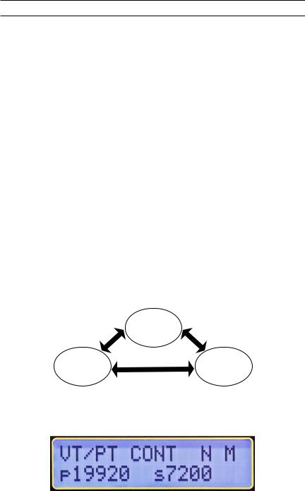
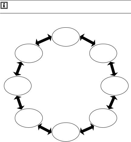
4.2Top Level Menu
The instrument has a top level control as shown in Fig. 4-1.
The user can navigate around the ring by pressing the ▼ or ▲ key.
Main Screen
Configuration
 Recall Data
Figure 4-1
Once the instrument is turned on, it initializes and then displays the Main
Screen:
Figure 4-2
Digital Transformer Ratiometer DTR® Model 8510 |
13 |
•Main Screen: Displays the Test Type, Test Mode, Filter [Fast (F), Normal (N) or Slow (S)], Storage Mode [Auto (A) or Manual (M)] and the Present Nameplate values (if enabled).
•Configure Instrument: Configures the instrument (see § 4.3).
•Recall Data: Stored data can be selected and displayed (see § 4.4).
NOTE: The program flow is two or three levels deep at various points. The available choices for a level can be viewed by pressing the ▼ or ▲ keys.
The ENTER key is used to select the following functions:
•Enter configuration menu.
•Enter Recall Data menu.
•Initiate storage of test results, accept location parameters and store the Measurement Record.
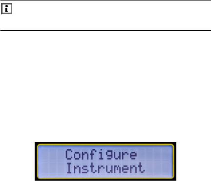
4.3Configure Instrument
With the display showing Configure Instrument, press the ENTER key. The configuration ring (see Figure 4-4) can be navigated around using the ▲ or ▼ key.
Figure 4-3
•Set Clock: Allows the setting of Time and Date.
•Setup Nameplate: Allows selection and editing of Present Nameplate voltages or ratios. Predefined ratios can only be edited through DataView®.
•Select Test Type: Allows the selection of Test Type (VT/PT or CT).
•Select Test Mode: Allows selection of the Test Mode (Ratio or Continuity/ Ratio in VT/PT Mode).
•Select Storage Mode: Allows the selection of data storage mode (Automatic or Manual).
14 |
Digital Transformer Ratiometer DTR® Model 8510 |
•Select Filter: Allows selection of filter (Fast, Normal, Slow). See § 4.3.6.
•Erase Memory: Allows deletion of all the stored measurement records
•Select Language: Allows selection of language on the display (English, French, German, Italian, Spanish, Portuguese)
NOTE: To move one level up and return to Configure Instrument, press the ▼▲ keys simultaneously.
Set
Clock
Select |
Setup |
Language |
Nameplate |
Erase Memory |
Select |
|
Test Type |
||
|
Select |
Select |
Filter |
Test Mode |
|
Select |
|
Storage Mode |
|
Figure 4-4 |
Digital Transformer Ratiometer DTR® Model 8510 |
15 |
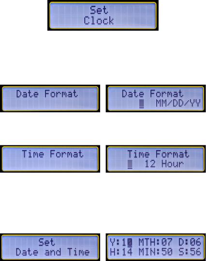
4.3.1Set Clock
1.Within the top level of Configure Instrument, press the ▼ or ▲ key until Set Clock appears on the display, then press ENTER.
Figure 4-5
The Set Clock configuration allows you to format the following:
Date Format: Allows the formatting of the date. (MM/DD/YY, DD/MM/YY, YY/MM/DD).
Figure 4-6
Time Format: Allows the formatting of the time (12 or 24 hours).
Figure 4-7
Set Date and Time: Allows the setting of the date and time in the selected format.
Note: Time must be set in the 24-hour format. It will be displayed withAM/ PM if the 12-hour format is chosen.
Figure 4-8
Example: To set the time to 2:50 PM, set the hour to 14 and the minutes to 50.
16 |
Digital Transformer Ratiometer DTR® Model 8510 |
To maneuver between the Set Clock configuration settings, perform the following:
1.Within the top level of Configure Instrument, press the ▼ or ▲ key until Set Clock appears on the display, then press ENTER to configure the date.
2.Use the ▼ or ▲ keys to view the choices. Press ENTER to make a selection. Once the format is selected, the display returns to Date Format.
3.Use the ▼ or ▲ keys to navigate to the other date and time options or press both ▼▲ keys together to return to the top level.
4.3.2Setup Nameplate
Nameplatevaluesareprimaryandsecondaryvoltages(orratios)associated with a given transformer. This information is available on the Nameplate of the transformer. The measured results will be compared with selected (edited) Nameplate values and Deviation will be displayed and stored in % relative to these values.
The DTR® 8510 allows the storage of 10 Nameplate voltages or ratios which can be individually selected for a given test.
NOTE:
•The Nameplate list of up to 10 transformers can be written to and saved only using DataView® software. The values in the list can be edited for use but cannot be saved from the front panel.
•The keys on the front panel can select any one of the 10 transformer Nameplate values. Once the transformer values are selected, they can be edited to a new value using the ▼, ▲ and ENTER keys. When the new values are selected (even
if they are not edited to new values), it becomes the Present Nameplate and will be used for all subsequent VT/PT and CT measurements. Deviation will be reported and stored using these values.
•The Present Nameplate values will be retained in memory even if the instrument is turned OFF and turned ON. However, it will not be saved in the list from which it was originally selected.
•The user can select another Nameplate from the list in the future and may or may not edit the values. As soon as the new Nameplate values are selected (and/or edited), it becomes the new Present Nameplate.
Digital Transformer Ratiometer DTR® Model 8510 |
17 |

•The Present Nameplate values are displayed in the Main
Screen.
•Each Measurement Record will record the Present Nameplate along with other associated parameters and will be available when the data is downloaded.
•The Ratio of the nameplate values must be between 1 and
32767.
•The Nameplate needs to be enabled. If the Nameplate is not enabled, the Deviation % will not be reported after the measurements. Subsequently, the stored values will not have Nameplate and Deviation % in the Measurement Record.
NOTE: The Main Screen will display the Present Nameplate only if it is Enabled. If it is not Enabled, it will display "---" for Primary and Secondary.
To configure the settings for the Nameplate, perform the following:
1.Within the top level of Configure Instrument, press the ▼ or ▲ key until Setup Nameplate appears on the display, then press ENTER.
Figure 4-9
2.The display will show Enable with Yes and No choices. Press the ▼ key to select Yes (Enable Nameplate).
Figure 4-10
18 |
Digital Transformer Ratiometer DTR® Model 8510 |
Loading...