


 Loading...
MEGOHMMETER
E N G L I S H User Manual
6501
6503

Statement of Compliance
Chauvin Arnoux®, Inc. d.b.a. AEMC® Instruments certifies that this instrument has been calibrated using standards and instruments traceable to international standards.
We guarantee that at the time of shipping your instrument has met its published specifications.
An NIST traceable certificate may be requested at the time of purchase, or obtained by returning the instrument to our repair and calibration facility, for a nominal charge.
The recommended calibration interval for this instrument is 12 months and begins on the date of receipt by the customer. For recalibration, please use our calibration services. Refer to our repair and calibration section at www.aemc.com.
Serial #: _ ________________________________
Catalog #: 2126.51/ 2126.52 Model #: 6501/6503
Please fill in the appropriate date as indicated:
Date Received: __________________________________
Date Calibration Due: ________________________
Chauvin Arnoux®, Inc. d.b.a AEMC® Instruments www.aemc.com

Table of Contents
1. INTRODUCTION............................................................ |
3 |
|
1.1 |
International Electrical Symbols...................................... |
4 |
1.2 |
Definition of Measurement Categories............................ |
4 |
1.3 |
Receiving Your Shipment................................................ |
5 |
1.4 |
Ordering Information........................................................ |
5 |
|
1.4.1 Accessories and Replacement Parts.................. |
5 |
2. |
PRODUCT FEATURES................................................... |
6 |
||
|
2.1 |
Description....................................................................... |
6 |
|
|
2.2 |
Features.......................................................................... |
6 |
|
|
2.3 |
Model 6501 Control Features.......................................... |
8 |
|
|
2.4 |
Model 6503 Control Features.......................................... |
9 |
|
3. |
SPECIFICATIONS........................................................ |
10 |
||
4. |
OPERATION................................................................ |
12 |
||
|
4.1 |
Auto-ranging.................................................................. |
12 |
|
|
4.2 |
Safety Check - Voltage Test.......................................... |
12 |
|
|
4.3 |
Insulation Resistance Testing (MΩ Range)................... |
12 |
|
|
|
4.3.1 |
Test Voltage....................................................... |
13 |
|
|
4.3.2 |
Spot Testing...................................................... |
13 |
|
|
4.3.3 |
Ratio Testing..................................................... |
14 |
|
4.4 |
Successful Insulation Resistance Testing...................... |
14 |
|
|
4.5 |
Utilization of the Guard Terminal (Model 6503).................... |
15 |
|
|
4.6 |
Insulation Measurement - Connections......................... |
17 |
|
|
4.7 |
Insulation Resistance on Motors................................... |
21 |
|
5. MAINTENANCE........................................................... |
24 |
|
5.1 |
Warning ........................................................................ |
24 |
5.2 |
Cleaning........................................................................ |
24 |
5.3 |
Fuse Replacement........................................................ |
25 |
Repair and Calibration.................................................................. |
26 |
|
Technical and Sales Assistance.................................................... |
26 |
|
Limited Warranty........................................................................... |
27 |
|
Warranty Repairs.......................................................................... |
27 |
|

CHAPTER 1
INTRODUCTION
 Warning
These safety warnings are provided to ensure the safety of personnel and proper operation of the instrument.
•Read the instruction manual completely and follow all safety information before operating this instrument.
•Safety is the responsibility of the operator!
•Tests are to be carried out only on dead circuits! Check for live circuits before making resistance measurements (safety check).
•These megohmmeters are rated for 600V CAT II or 300V CAT III - Pollution Degree 2.
•The Megohmmeter Models 6501/6503 are sources of high voltage, as is the sample connected to them. All persons performing or assisting in the tests must employ all safety precautions to prevent electrical shock to themselves and to others.
•AEMC® Instruments considers the use of rubber gloves to be an excellent safety practice even if the equipment is properly operated and correctly grounded.
•When testing capacitance samples, make sure that they have been properly discharged and that they are safe to touch. Dielectric insulation samples should be short-circuited for at least five times the amount of time they were energized.
•Use the leads supplied with the megohmmeter. If defective or used, replace before testing.
Megohmmeter Models 6501/6503 |
3 |
1.1International Electrical Symbols
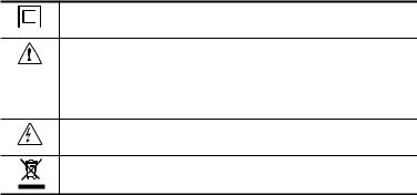
This symbol signifies that the instrument is protected by double or reinforced insulation.
This symbol on the instrument indicates a WARNING and that the operator must refer to the user manual for instructions before operating the instrument. In this manual, the symbol preceding instructions indicates that if the instructions are not followed, bodily injury, installation/sample and product damage may result.
Risk of electric shock. The voltage at the parts marked with this symbol may be dangerous.
In conformity with WEEE 2002/96/EC
1.2Definition of Measurement Categories
CAT II: For measurements performed on circuits directly connected to the electrical distribution system. Examples are measurements on household appliances or portable tools.
CAT III: For measurements performed in the building installation at the distribution level such as on hardwired equipment in fixed installation and circuit breakers.
CAT IV: For measurements performed at the primary electrical supply (<1000V) such as on primary overcurrent protection devices, ripple control units, or meters.
4 |
Megohmmeter Models 6501/6503 |
1.3Receiving Your Shipment
Upon receiving your shipment, make sure that the contents are consistent with the packing list. Notify your distributor of any missing items. If the equipment appears to be damaged, file a claim immediately with the carrier and notify your distributor at once, giving a detailed description of any damage. Save the damaged packing container to substantiate your claim. Do not use an instrument that appears to be damaged.
1.4Ordering Information
Megohmmeter Model 6501..................................... |
Cat. #2126.51 |
Includes a soft carrying case, two color-coded leads, two insulated alligator clips, test probe and user manual.
Megohmmeter Model 6503..................................... |
Cat. #2126.52 |
Includes a soft carrying case, three color-coded leads, three insulated alligator clips, test probe and user manual.
1.4.1Accessories and Replacement Parts
Replacement soft carrying case................................ |
Cat. #2126.71 |
Replacement leads (black and red), alligator clips |
|
(black and red) and one safety test probe (6501)...... |
Cat. #2126.72 |
Replacement leads (black, red and blue), alligator clips (black, |
|
red and blue) and one safety test probe (6503)......... |
Cat. #2126.73 |
Replacement Fuse - 0.2A, 600V HPC (6501)............. |
Cat. #2970.95 |
Megohmmeter Models 6501/6503 |
5 |

CHAPTER 2
PRODUCT FEATURES
2.1Description
The AEMC® Models 6501 and 6503 are compact, self-contained hand-cranked megohmmeters. They are practical and dependable instruments designed for a broad range of plant and field service applications,suchasacceptancetestingandpreventivemaintenance of wiring, cables, switchgear, and motors. The easy hand-cranked operation provides a steady rectified DC voltage output across the entire range for consistently reliable readings.
These megohmmeters incorporate a built-in generator and a constant DC voltage circuit to provide a stable output and give direct insulation resistance reading.
The Models 6501/6503 have a unique auto-ranging feature which expands the scale by x10 and almost doubles the scale length. When the pointer reaches near the end of scale, the auto-ranging feature activates, returning the pointer to the beginning of the scale with the x10 red LED indicator on.
Insulation resistance is indicated with a rugged taut-band meter movement on a logarithmic scale. The indicator scale is easy to read.
2.2Features
•Measures insulation at 500V, resistance and continuity (Model 6501)
•Three test voltages: 250V, 500V, 1000V (Model 6503)
6 |
Megohmmeter Models 6501/6503 |
•Test voltage constant across the entire measurement range
•Autoranging MΩ, kΩ and Ω ranges (Model 6501)
•Autoranging MΩ ranges (Model 6503)
•Designed for harsh environments: offshore, mining, heavy-duty field, industrial, and military use
•Compact, self-contained package; folding crank
•Large direct reading scale
•600V test voltage range (safety check)
Megohmmeter Models 6501/6503 |
7 |
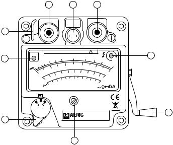
2.3Model 6501 Control Features
1 |
2 |
3 |
FUS
9
8
7
x 10 |
|
|
600V CAT II / 1000V CAT I |
! |
|
|
|
|
|
||||||
|
|
|
|
|
|
1 |
|
|
|
|
|
|
|
|
|
|
|
|
3 |
2 |
|
|
|
|
|
|
|
|
|
|
|
|
4 |
|
|
|
|
|
|
|
|
|
|
|
|||
|
|
|
|
|
|
|
|
|
|
|
|
|
|||
10 |
5 |
|
|
|
|
20 |
|
30 |
|
|
|
|
|
0. |
|
20 |
|
|
|
|
|
|
|
40 |
|
|
5 |
||||
|
|
|
10 |
|
|
|
|
|
|
|
50 |
(500V) |
|||
ΜΩ |
|
|
|
|
5 |
|
|
|
|
|
|
|
|||
0 |
|
|
2 |
3 |
4 |
6 |
7 |
|
8 |
|
|
(1mA) |
|||
κΩ |
|
|
1 |
|
|
|
300 |
|
|
|
|
9 |
10 |
(5mA) |
|
|
Ω |
0 |
|
|
200 |
400 |
500 |
|
|||||||
|
|
|
|
|
|
||||||||||
|
|
100 |
|
|
600 |
|
|||||||||
|
|
|
|
|
|
|
|
|
|
|
|
! C |
|||
|
V |
0 |
|
|
|
|
|
|
|
|
|
|
|||
|
|
|
|
|
|
|
|
|
|
|
|
2 |
|
42 |
|
|
|
|
|
|
|
|
|
|
|
|
|
|
|
||
Ω |
|
Ω |
|
|
|
|
|
|
|
|
|
|
|
|
|
M |
kΩ |
|
|
|
|
|
|
|
|
|
|
|
|
|
|
V |
|
|
|
|
|
|
|
® MEGOHMMETER |
|
||||||
|
|
|
|
|
|
|
|
|
|
||||||
|
|
|
|
|
|
|
INSTRUMENTS |
|
Model 6501 |
|
|||||
6
Figure 2-1
4
5
1.Line (-) terminal Black
2.Fuse 0.2A
3.Earth (+) terminal Red
4.Amber LED illuminates when proper crank speed is attained, indicating presence of selected output
5.Foldaway handle
6.Mechanical zero adjustment screw
7.Range switch - safety test first on MΩ/V range to 600VAC
8.Autoranging: Red LED illuminates when reading needs to be multiplied x10 to obtain the true value (MΩ, kΩ, Ω ranges)
9.Security finger rest isolates users hand from terminals while giving a firm grip during an operation
8 |
Megohmmeter Models 6501/6503 |
Loading...