

Page 1

Installation Instructions for:
EMS P/N 30-6053
Fits vehicles:
2006-2008 Honda S2000 AP2 F22C1
WARNING:
This installation is not for the tuning novice nor the PC illiterate!
Use this system with EXTREME caution! The AEM EMS System
allows for total flexibility in engine tuning. Misuse of this
product can destroy your engine! If you are not well versed in
,!
This product is legal in California for racing vehicles only and should never be used
engine dynamics and the tuning of management systems or are
not PC literate, please do not attempt the installation. Refer the
installation to a AEM trained tuning shop or call 800-423-0046
for technical assistance. You should also visit the AEM EMS
Tech Forum at http://forum.aempower.com/forum/index.php
NOTE: AEM holds no responsibility for any engine damage that
results from the misuse of this product!
on public highways.
Vehicle fitment Series II EMS
2006-2008 Honda S2000 AP2 F22C1 30-6053
© 2010 Advanced Engine Management, Inc.
ADVANCED ENGINE MANAGEMENT INC.
th
2205 126
Street Unit A Hawthorne, CA. 90250
Phone: (310) 484-2322 Fax: (310) 484-0152
http://www.aempower.com
Instruction Part Number: 10-6053
Page 1 of 21
Page 2

Thank you for purchasing an AEM Engine Management System.
The AEM Engine Management System (EMS) is the result of extensive development on a
wide variety of cars. Each system is engineered for each particular application. The AEM
EMS differs from all others in several ways. The EMS is a stand alone system which
replaces the fuel and ignition functions of the factory ECU and features unique Plug and Play
Technology, which means that each system is configured especially for your make and
model of car.
For stock and slightly modified vehicles, the supplied startup calibrations are configured to
work with OEM sensors, providing a solid starting point for beginner tuning. For more heavily
modified cars, the EMS can be reconfigured to utilize aftermarket sensors and has many
spare inputs and outputs allowing the elimination of add-on rev-limiters, boost controllers,
nitrous controllers, fuel computers, etc. It also includes a configurable onboard 1MB data
logger that can record any 16 EMS parameters at up to 250 samples per second. Every
EMS comes with all functions installed and activated; there is no need to purchase options or
upgrades to unlock the full potential of your unit.
The installation of the AEM EMS on the supported vehicles uses the stock sensors and
actuators. After installing the AEMTuner software, the startup calibration will be saved to the
following folder on your PC:
C:\Program Files\AEM\AEMTuner\Calibrations\Honda - Acura\
Multiple calibrations may be supplied for each EMS; additional details of the test vehicle
used to generate each calibration can be found in the Calibration Notes section for that file.
Please visit the AEM Performance Electronics Forum at http://www.aempower.com and
register. We always post the most current strategy release, PC Software and startup
calibrations online. On the forum, you can find and share many helpful hints/tips to make
your EMS perform its best.
TUNING NOTES AND WARNING:
While the supplied startup calibration may be a good starting point and can save
considerable time and money, it will not replace the need to tune the EMS for your specific
application. AEM startup calibrations are not intended to be driven aggressively before
tuning. We strongly recommend that every EMS be tuned by someone who is already
familiar with the AEM software and has successfully tuned vehicles using an AEM EMS.
Most people make mistakes as part of the learning process; be warned that using your
vehicle as a learning platform can damage your engine, your vehicle, and your EMS.
Page 2 of 21
Page 3

Read and understand these instructions BEFORE attempting to install this product.
• Sufficient battery voltage during cranking (starting)
Having enough battery voltage when you crank over your vehicle is critical to the
operation of your vehicle and your AEM EMS. For the EMS to function properly, the
battery voltage must remain at or above 8 Volts when the vehicle is first starting. This
is the time when your electrical system will be worked its hardest and be at its lowest
voltage. If you are connected to your Series 2 EMS with a USB communications
cable, and you experience disconnecting while the vehicle is cranking, the reason is
most likely a battery voltage of less than 8 volts (see Channel called “Battery Raw”
which is an unfiltered value of actual battery voltage being received by the EMS). If
this is the case, you can confirm this by connecting with a serial cable (a serial
adapter may be required if your computer is not equipped with a serial port) and
check in the AEMTuner software for a Channel called “Run Time” as well as the
“Battery Raw” to see at what voltage the EMS cuts out at. “Run Time” is the amount of
time, in seconds, that the EMS has been turned on for. If you notice that this Channel
resets to zero while the EMS is communicating with the computer and the vehicle is
being cranked, that means the EMS has had lower than 8 Volts at some point and has
reset the system. A thorough wiring check may reveal a large voltage drop causing
this problem, or it may simply be the need for a new or a larger battery.
• AEM adapter harness
The 2006-2008 Honda S2000 uses an electronically controlled throttle which will
remain controlled by the original ECU. The adapter harness provided will allow the
user to retain the original electronically controlled throttle while still being able to
control all other engine management aspects that you have come to expect from
AEM. In addition, the stock instrument cluster, air conditioning, and emissions controls
will continue to work as normal controlled by the original Honda ECU.
• Vehicle speed sensor
Currently, the speed sensor is the only circuit that causes a check engine light. This
will not affect the function of the electronically controlled throttle.
• Engine Wiring Harnesses, ‘swapped’ engine installations
It would be very wise to double-check that the pinout destinations for the circuits is
accurate to the provided documentation. This is especially true if the vehicle contains
a ‘swapped’ engine or if the wiring harness has been cut, spliced, soldered, tapped or
modified in any manner. It is the user’s responsibility to check that the wiring on the
vehicle matches the pinout chart in this document. AEM will not be held responsible
for loss or damage that can occur if the EMS is installed in a vehicle in which the
wiring harness does not match the AEM-supplied pinout chart!
• Retaining original O2 sensor
For the malfunction code for this sensor to remain off, the stock oxygen sensor must
be retained. However, when the air-fuel ratio is too rich with this sensor, in the case of
a turbo application, the check engine light will still come on. This will not have any
affect on the operation of the car including the electronically controlled throttle.
• Knock sensor
In the AEM wiring harness, the stock knock sensor has been tapped rather than
intercepted to keep the stock ECU from thinking it has a malfunction. The knock
sensor is less sensitive but still functional and the calibration for the sensor is lower by
0.3 Volts in the AEMTuner calibration. If you would like the knock sensor to be more
Page 3 of 21
Page 4
sensitive, you can depin Pin A1 that goes into the stock ECU, but the malfunction
code for this sensor will turn on. If this is done, the knock sensor calibration will need
to have 0.3 Volts added to each breakpoint in the calibration.
• Traction control function
When active, the stock traction control system will be affected by adding the EMS.
The stock traction control system uses throttle, fuel, and ignition changes for the
traction control system. Since the fuel and ignition are no longer controlled by the
stock ECU, these aspects of traction control must now be configured in the calibration
in the EMS. The throttle will still be cut as normal, but the traction and stability control
warning lights will stay on after the system is no longer activated and will reset when
the vehicle is turned off.
• EMS Fuel Map, Boost Fuel Trim Table
The 30-6053 calibration maps provided utilize the “Boost Fuel Trim Table” to provide
a 1:1 fuel compensation above atmospheric pressure. However, since the calibration
was created on a naturally aspirated vehicle (A calibration is provided above 100 kPa)
it has not been tested in boost and must be tuned to your application if turbo or
supercharged. To use this table, the “Boost Fuel Trim Table” should be configured to
provide twice as much fuel when the manifold pressure is twice as high and half the
fuel when the manifold pressure is half as high; this should help simplify the tuning
process for different vacuum and boost levels. Notice the values in the main “Fuel
Map” do not change above 100 kPa (0 psi boost), the fuel correction is being made by
the “Boost Fuel Trim Table.”
Note: the “Boost Fuel Trim Table” must be adjusted if a different MAP sensor is
installed or if the Load breakpoints are adjusted. The Boost Fuel Trim value should be
set to -90 at 10kPa, 0 at 100 kPa, +100 at 200 kPa, +200 at 300 kPa, etc…
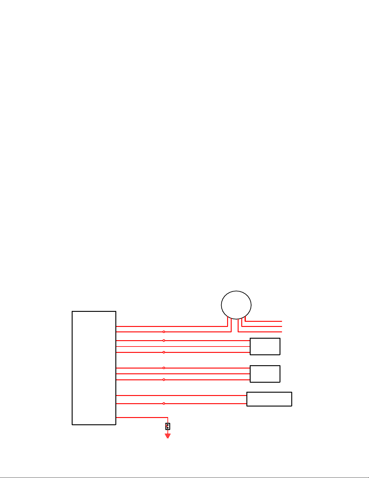
• Wiring accessories to the EMS
Please follow this suggested wiring diagram when adding new accessories and
retaining original accessories such as UEGO gauges, MAP sensors, MAF sensors,
IAT sensors, or switches for use with the EMS. Note that wire polarity is not important
for the Air Temperature sensor.
AEM EMS P/N: 30-6053
C16
A7, A31, C7, C18, or D9
C19 or C28
C17
A7, A31, C7, C18, or D9
C19 or C28
A29
A7, A31, C7, C18, or D9
C25
A7, A31, C7, C18, or D9
O2 Sensor 1
Sensor Ground (tapped)
+5V Sensor Power (tapped)
MAP Signal
Sensor Ground (tapped)
+5V Sensor Power (tapped)
MAF Signal
Sensor Ground (tapped)
IAT Sensor
Sensor Ground (tapped)
Switched Input
A31
White (0-5V Analog + signal)
Switch 1
Ground
Page 4 of 21
Brown (Analog - signal)
Red (+5V Sensor Power)
Green (MAP Signal)
Black (Sensor Ground)
Red (+5V Sensor Power)
Black (Sensor Ground)
AEM UEGO
P/N: 30-5130
Pink (Switched +12V Powe r)
Red (+12V power, 5A fuse)
Black (Battery or chassis ground)
MAP Sensor
P/N: 30-2130-50
MAF Signal
MAF Sensor
Air Temperature Sensor
P/N: 30-2010
Page 5
1) Install AEMTuner software onto your PC
The latest version of the AEMTuner software can be downloaded from the AEMTuner
section of the AEM Performance Electronics forums found at www.aemelectronics.com
Series 2 units are not supported by the older AEMPro tuning software.
2) Connect AEM adapter harness
a) Disconnect negative terminal from battery
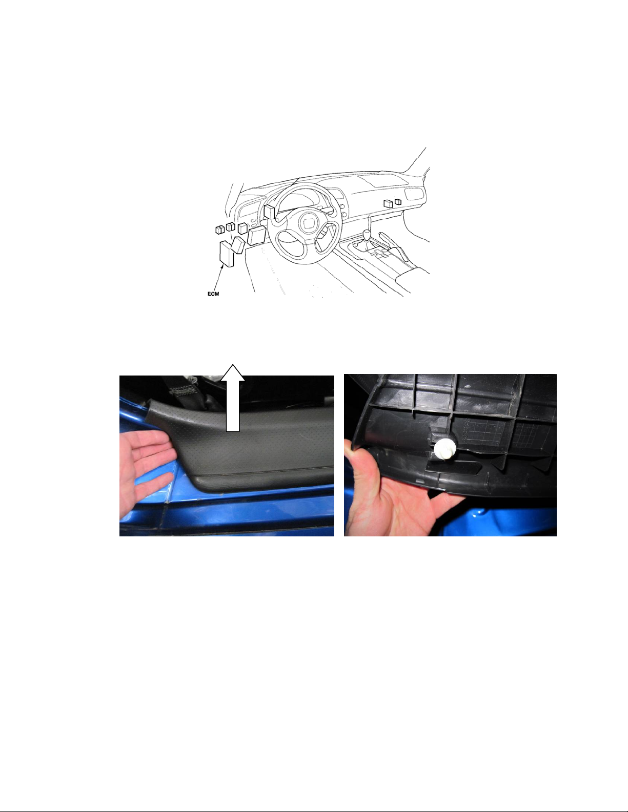
b) Access the stock Engine Control Unit (ECU). The location of the ECU on the Honda
S2000 is behind the left side driver’s side kick panel.
Honda S2000
c) Remove kick panel that covers the original ECU and the plastic cover on the lower
driver’s side door sill. The door sill cover is held in with plastic clips as shown
below.
Remove sill cover Clips holding sill cover
Page 5 of 21
Page 6
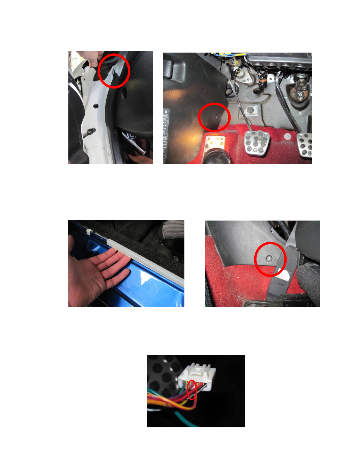
d)
Remove the clip that is hidden underneath the rubber sealing trim next to the
dashboard and the clip for the plastic cover over the stock ECU using a plastic pry
tool to avoid scratching the paint and plastic cover.
e)
Remove the carpeting that runs along the lower driver’s side door sill to place the
wiring harness provided. Next, remove the two screws holding the plastic cover
behind the driver’s seat to place the EMS in the area behind the seat.
Remove clip Remove clip
Remove carpet covering harness Remove screw holding plastic cover
f)
Tap pin 3 on the red/blue TPS wire on the stock wiring harness using the provided
wire-tap. It is located on the white 6-pin connector near the stock ECU shown
below.
Tap pin 3 (red/blue wire) on 6-pin connector
Page 6 of 21
Page 7
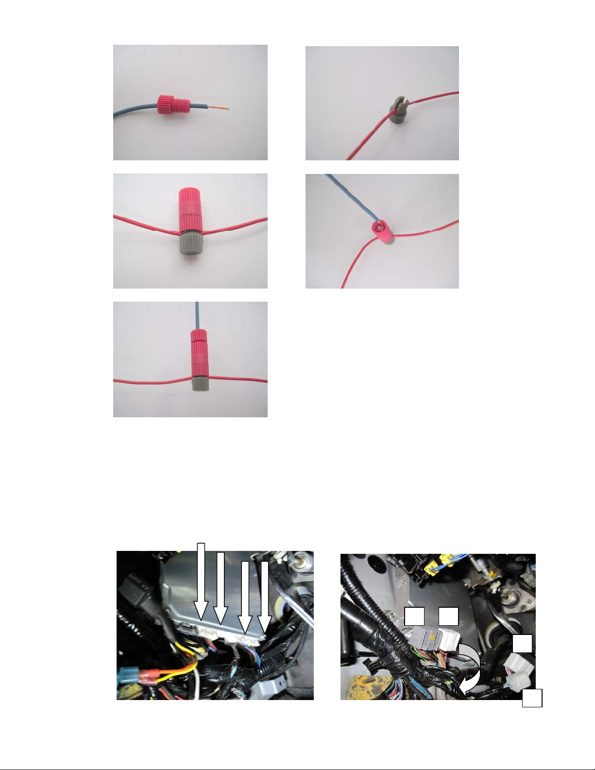
g)
A
How to use provided wire taps:
Run harness TPS wire through Place vehicle wire in tap
Screw in tap onto vehicle wire Place harness TPS wire as shown
Screw TPS wire into tap
h)
Carefully disconnect the wiring harness from the ECU. Avoid excessive stress or
pulling on the wires, as this may damage the wiring harness. All connectors must
be removed without damage to work properly with the AEM ECU. Do not cut any
of the wires in the factory wiring harness to remove them. Next to the stock ECU
on the stock wiring harness, the A and B connectors should be routed underneath
the D and E connectors to make them easier to install.
B
E
D
Carefully remove ECU connectors Reroute connectors
Page 7 of 21
Page 8

i)
Connect provided adapter harness to factory wiring harness and stock ECU. Then
route the harness from the stock ECU through the driver’s side door sill and
underneath the driver’s side seat. Take note of the bends that the harness will
require so that the plastic cover that protects the harness will fit over the AEM
wiring harness. A few zip ties will hold the harness against the stock ECU so that
the clutch pedal will not contact it. See photo above to get an idea of the stock
clearance of the ECU and clutch pedal.
Plug in adapter harness to stock wiring Plug in adapter harness to stock ECU
j)
Mount the AEM EMS behind the seat in the upright position to maximize seat
adjustment using the Velcro strips provided. Make sure the EMS is not impacted
by the seat when moving it back into place.
k)
EMS location
Reinstall the covers in the reverse of removal. Make sure that the cover that goes
over the original ECU and now the adapter harness fits so that it is not contacting
the clutch pedal.
Page 8 of 21
Page 9
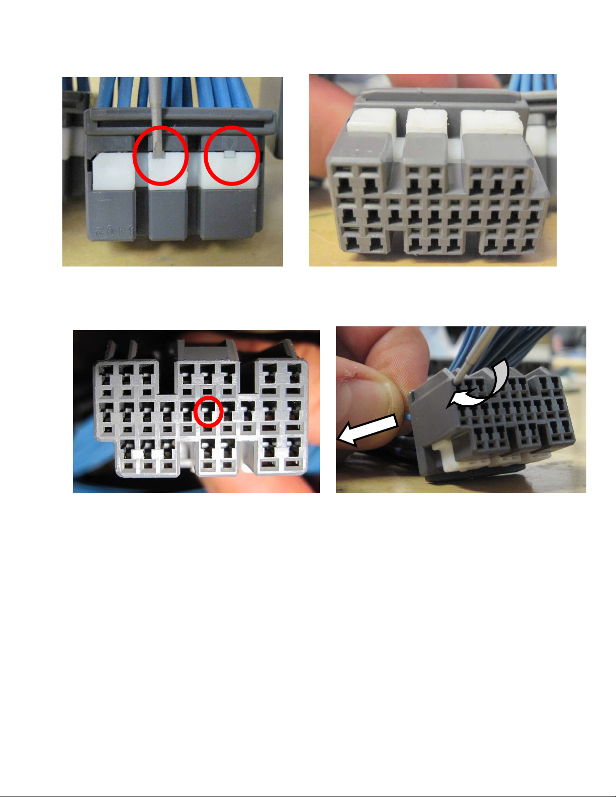
2) Repin ECU pins (only necessary if adding or relocating ECU pins)
a) Locate a small screwdriver (a precision 1.5mm wide flathead screwdriver is
recommended) and carefully pry white plastic retainer using both slots in the retainer
so it disengages vertically about 1mm as shown in the following pictures:
Screwdriver lifts here Plastic retaining mechanism after lifting
b) Next remove the metal pin from the plastic connector by lightly prying on the plastic
tabs that secure the metal pin in the plastic connector while pulling on the wire at the
same time as shown below.
Pry this tab up to release the pin While prying tab up, gently pull pin back
3) Install the AEM Engine Management System
a) Plug the provided wiring harness into the AEM EMS and position it so the wires are
not pulled tight or stressed in any manner.
b) Secure the EMS with the provided Velcro fasteners behind driver’s side seat.
c) Reconnect the negative battery terminal.
d) Plug the communications cable into the EMS and into your PC.
e) Turn the ignition on, but do not attempt to start the engine.
f) At the time these instructions were written, new EMS units do not require USB drivers
to be installed on the PC. The EMS will automatically be detected as a human
interface device (HID).
g) With the AEMTuner software open, select ECU>>Upload Calibration to upload the
startup calibration file (.cal) that most closely matches the vehicle’s configuration to
be tuned. Check the Notes section of the calibration for more info about the vehicle it
was configured for. These files can be found in the following folder:
C:\Program Files\AEM\AEMTuner\Calibrations\Honda - Acura\
Page 9 of 21
Page 10

h) NOTE: the throttle range on this vehicle is set differently from other EMS applications!
Disconnect the DBW connector on the throttle, then perform the procedure as follows
by holding the throttle open and closed manually at the throttle plate.
Set the throttle range: Select Wizards>>Set Throttle Range. When finished, check
that the ‘Throttle’ channel never indicates less than 3.2% or greater than 99.8% (must
be 2.2% or more since the DBW throttle will close slightly when the engine starts),
this is considered a sensor error and may cause some functions including idle
feedback and acceleration fuel to operate incorrectly. Since this application uses the
original drive-by-wire system, it is highly recommended that after calibration is
complete, the throttle is rechecked to ensure that the minimum throttle never causes
the Error Throttle channel to turn on. This would happen when the vehicle is off and
the key is turned on.
4) Ready to begin tuning the vehicle.
a) Before starting the engine, verify that the fuel pump runs for a couple of seconds
when the key is turned on and there is sufficient pressure at the fuel rail.
If a MAP sensor is installed, check that the Engine Load indicates something near
atmospheric pressure (approximately 101kPa or 0 PSI at sea level) with the key on
and engine off. Press the throttle and verify that the ‘Throttle’ channel responds but
the Engine Load channel continues to measure atmospheric pressure correctly.
b) Start the engine and make whatever adjustments may be needed to sustain a safe
and reasonably smooth idle. Verify the ignition timing: Select Wizards>>Ignition
Timing Sync from the pull-down menu. Click the ‘Lock Ignition Timing’ checkbox
and set the timing to a safe and convenient value (10 degrees BTDC for instance).
Remove the cylinder 1 ignition coil (closest to front of engine), add a spark plug wire
between the ignition coil and the spark plug and place the timing light pickup on the
added spark plug wire. Use a timing light to compare the physical timing numbers to
the timing value you selected. Use the Sync Adjustment Increase/Decrease buttons
to make the physical reading match the timing number you selected.
Crankshaft timing marks are not labeled for some vehicles. Consult the factory
service manual for more information. The diagram below shows labels for the original
timing marks. “A” points to the timing indicator and “B” points to the red mark that is
located 5° before top dead center.
Page 10 of 21
Page 11

c) Note: This calibration needs to be properly tuned before driving the vehicle. It is
intended for racing vehicles and may not operate smoothly at idle or part-throttle.
NEVER TUNE THE VEHICLE WHILE DRIVING
5) Troubleshooting an engine that will not start
a) Double-check all the basics first. Engines need air, fuel, compression, and a
correctly-timed spark event. If any of these are lacking, we suggest checking simple
things first. Depending on the symptoms, it may be best to inspect fuses, sufficient
battery voltage, properly mated wiring connectors, spark using a timing light or by
removing the spark plug, wiring continuity tests, measure ECU pinout voltages,
replace recently-added or untested components with known-good spares. Check that
all EMS sensor inputs measure realistic temperature and/or pressure values.
b) If the EMS is not firing the coils or injectors at all, open the Start tab and look for the
‘Stat Sync’d’ channel to turn ON when cranking. This indicates that the EMS has
detected the expected cam and crank signals; if Stat Sync’d does not turn on,
monitor the Crank Tooth Period and T2PER channels which indicate the time
between pulses on the Crank and T2 (Cam) signals. Both of these channels should
respond when the engine is cranking, if either signal is not being detected or
measuring an incorrect number of pulses per engine cycle the EMS will not fire the
coils or injectors.
c) If the Engine Load changes when the throttle is pressed this usually indicates that
there is a problem with the MAP sensor wiring or software calibration (when the EMS
detects that the MAP Volts are above or below the min/max limits it will run in a
failsafe mode using the TPS-to-Load table to generate an artificial Engine Load signal
using the Throttle input). This may allow the engine to sputter or start but not continue
running properly.
Page 11 of 21
Page 12

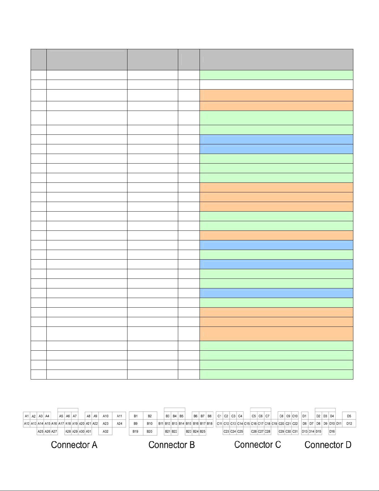
Original Honda S2000 ECU Pinout
This pinout is for the original wiring harness on the Honda S2000 showing the corresponding
pin on the AEM EMS through the adapter harness.
Please note: Connector C is not present in the original wiring harness.
Pin Name
Knock sensor (Knock 1 on EMS) C3 tapped
A1
Ignition power 2 -- --
A2
Ignition power 1 -- --
A3
Power ground 2 (Power ground on EMS) B10 tapped
A4
Power ground 1 (Power ground on EMS)
A5
Camshaft position sensor (T2 on EMS) C20 tapped
A6
Crankshaft position sensor (T1 on EMS) C8 tapped
A7
Logic Ground 2 -- --
A8
Logic Ground 1
A9
AF sensor heater -- --
A10
-- -- --
A11
-- -- --
A12
Ignition Coil 4 (Coil 4 on EMS) C14 intercepted
A13
Ignition Coil 3 (Coil 3 on EMS) C13 intercepted
A14
Ignition Coil 2 (Coil 2 on EMS) C12 intercepted
A15
Ignition Coil 1 (Coil 1 on EMS) C4 intercepted
A16
-- -- --
A17
Vehicle Speed Sensor (T3 on EMS) C23 tapped
A18
-- -- --
A19
Sensor Voltage 2 -- --
A20
Sensor Voltage 1 -- --
A21
-- -- --
A22
Sensor Ground 2 (Sensor ground on EMS) C18 tapped
A23
Sensor Ground 1 (Sensor ground on EMS) C7 tapped
A24
Accelerator Pedal Position B -- --
A25
Accelerator Pedal Position A -- --
A26
-- -- --
A27
AF sensor 1 signal (-) -- --
A28
-- -- --
A29
MAP signal (MAP on EMS) C17 tapped
A30
AF sensor 1 signal (+) -- --
A31
AEM EMS
pin location
B2
Relay pins 2 & 4
--
Wire view of original ECU connector
Tapped or
intercepted?
tapped
--
Page 12 of 21
Page 13

Pin Name
-- (HS 4 on EMS) D4 intercepted
B1
Injector 4 (Injector 4 on EMS) B5 intercepted
B2
Injector 3 (Injector 3 on EMS) B4 intercepted
B3
Injector 2 (Injector 2 on EMS) B3 intercepted
B4
Injector 1 (Injector 1 on EMS) B11 intercepted
B5
VTEC solenoid valve (HS 1 on EMS) B12 intercepted
B6
-- -- --
B7
Coolant Temperature signal 1 (CLT on EMS) C26 tapped
B8
-- -- --
B9
Alternator L signal -- --
B10
VTEC oil pressure switch B10 (stock ECU side) intercepted
B11
-- -- --
B12
Alternator FR signal -- --
B13
-- -- --
B14
Engine mount control solenoid valve -- --
B15
-- -- --
B16
Intake Air Temperature signal (AIT on EMS) C25 tapped
B17
Alternator Control signal (LS 3 on EMS) -- --
B18
Throttle Actuator signal SEFD -- --
B19
Throttle Actuator signal SEDF -- --
B20
Evap Emission Canister purge valve -- --
B21
-- -- --
B22
-- -- --
B23
-- -- --
B24
AEM EMS
pin location
Tapped or
intercepted?
Pin Name
Cruise Control set switch -- --
D1
-- -- --
D2
-- -- --
D3
Cruise Control main switch -- --
D4
-- -- --
D5
-- -- --
D6
Cruise Control resume switch -- --
D7
Brake pedal position switch -- --
D8
Cruise Control clutch signal -- --
D9
-- -- --
D10
-- -- --
D11
-- -- --
D12
-- -- --
D13
-- -- --
D14
Throttle Actuator Relay -- --
D15
-- -- --
D16
-- -- --
D17
AEM EMS
pin location
Tapped or
intercepted?
Wire view of original ECU connector
Page 13 of 21
Page 14

Pin Name
Engine Coolant Temperature sensor 2 -- --
E1
-- -- --
E2
Logic Ground 3 -- --
E3
Sensor Ground 3 -- --
E4
Sensor Voltage 3 -- --
E5
-- -- --
E6
Main Relay control -- --
E7
AF sensor heater relay -- --
E8
Ignition signal (ignition signal on EMS) Relay pin 1 & B1 tapped
E9
-- -- --
E10
CAN High -- --
E11
Radiator Fan control (LS 8 on EMS) A20 intercepted
E12
SEFMJ multiplex communication -- --
E13
Fuel Tank Pressure sensor -- --
E14
Electrical Load detector -- --
E15
Power Steering Load detector -- --
E16
Fuel Pump relay (LS 1 on EMS) A15 intercepted
E17
A/C Compressor clutch relay A17 intercepted
E18
Evap Canister vent shut valve -- --
E19
Secondary O2 sensor signal -- --
E20
Secondary O2 sensor heater -- --
E21
Brake Pedal position switch -- --
E22
-- -- --
E23
CAN Low -- --
E24
Engine speed pulse -- --
E25
Vehicle speed out -- --
E26
Immobilizer code -- --
E27
A/C switch signal -- --
E28
Service Check signal -- --
E29
Write Enable signal -- --
E30
-- -- --
E31
AEM EMS
pin location
Tapped or
intercepted?
Wire view of original ECU connector
Page 14 of 21
Page 15

Application Notes for EMS P/N 30-6053
F22C1
Make: Acura/Honda Description Function Pin
Model: S2000 Spare Injector Drivers: Injector 5 D1
Years Covered: 2006-2008 Spare Injector Drivers: Injector 6 B19
Engine Displacement: 2.2L Spare Injector Drivers: Injector 7 D2
Engine Configuration: Inline 4 Spare Injector Drivers: Injector 8 B16
Firing Order: 1-3-4-2 Spare Injector Drivers: Injector 9 A12 or A13
N/A, S/C or T/C: N/A Spare Injector Drivers: Injector 10 C11
Load Sensor Type: MAP Spare Injector Drivers: Injector 11 A14
MAP Min: 0.32V @ -13.9 psi Spare Injector Drivers: Injector 12 A10
MAP Max: 4.84V @ 10.94 psi Spare Coil Drivers: Coil 7 A13*
# Coils: 4 smart coils with built in ignitors Spare Coil Drivers: Coil 8 A22*
Ignition driver type: 0-5V Falling Edge trigger Boost Solenoid: PW 2 D16
# of Injectors: 4 (Inj 1-4) Spare PWM Freq Driver: PW 1 B15 or B23
Factory Injectors: 360 cc/min saturated EGT 1 Location: EGT 1 A5
Factory Inj Resistors: No EGT 2 Location: EGT 2 D7
Injection Mode: Sequential EGT 3 Location: EGT 3 A30
Knock Sensors used: 1 (Knock 1) EGT 4 Location: EGT 4 C5
Lambda Sensors used: Spare 0-5V Input Channel: ADCR03 A29
Spare 0-5V Input Channel: ADCR11 C6
Idle Control: Stock electronic throttle Spare 0-5V Input Channel: ADCR14 D8
Main Relay Control: Controlled by stock ECU Spare Low Side Output Driver: Low side 1 A2
Crank Pickup Type: Hall Effect (3-wire) Spare Low Side Output Driver: Low side 2 C1
Crank Teeth/Cycle: 24 plus 2 Spare Low Side Output Driver: Low side 4 A6
Cam Pickup Type: Hall Effect (3-wire) Spare Low Side Output Driver: Low side 5 A4
Cam Teeth/Cycle: 4 plus 1 Spare Low Side Output Driver: Low side 7 A19
Transmissions Offered: Manual Spare Low Side Output Driver: Low side 10 A18
Trans Supported: Manual Spare Low Side Output Driver: Low side 12 A8
Drive Options: RWD Spare Low Side Output Driver: Idle 2 A28
Supplied Connectors: N/A Spare Low Side Output Driver: Idle 4 D5
AEM Extension/patch harness 30-2986C (from vehicle harness) Spare Low Side Output Driver: Idle 6 B17
AEM Plug/pin kit 35-2610 Spare Low Side Output Driver: Idle 8 B25
VTEC High Side Driver: High side 1 B12
Spare High Side Driver: High side 2 B7
Spare High Side Driver: Idle 1 D3
Spare High Side Driver: Idle 3 A25
Spare High Side Driver: Idle 5 B8
Spare High Side Driver: Idle 7 B18
Spare Switch Input: Switch 1 A32
Spare Switch Input: Switch 2 D11
Spare Switch Input: Switch 3 D12
Spare Switch Input: Switch 5 C10
A/C Switch Input: Switch 6 A27
1 (O2 # 1, wideband sensor required,
original O2 sensor used only for
original check engine light)
Spare 0-5V Input Channel: ADCR13 C24
Wire View of AEM EMS
WARNING:
*The Coil 7 and Coil 8 outputs are intended only for use with ignitors (or smart coils with built-in
ignitors). Do not connect these pins directly to 2-wire direct-fire ignition coils (a.k.a. ‘dumb’ coils);
doing so will damage your EMS and void your warranty.
All switch input pins must connect to ground, the switch should not provide 12V power to the EMS
because that will not be detected as on or off. Connecting 12V power to the switch input pins may
damage your EMS and void your warranty.
Page 15 of 21
Page 16

Connection Diagram for EMS P/N 30-6053
Please note that the following pinout is for the AEM EMS and not the original Honda S2000
wiring harness.
PnP
Available Means the function is not currently allocated and is available for use
Dedicated Means the location is fixed and cannot be changed
Not used Means that the AEM EMS does not use this pin location for this application
AEM adapter harness pinout
Pin
A1 --
A2 Fuel pump Low side 1 Output PnP for fuel pump activation
A3 -- Low side 3 Output Available, switched ground, 1.5A max
A4 VTEC stock computer oil pressure switch Low side 5 Output PnP for VTEC oil pressure switch
A5 -- EGT 1 Input
A6 -- Low side 4 Output Available, switched ground, 1.5A max
A7 -- Sensor ground Output Available, filtered ground for sensors
A8 -- Low side 12 Output Available, switched ground, 1.5A max
A9 -- Vehicle Speed (T3) Input Available, vehicle speed sensor (connected to C23)
A10 -- Injector 12 Output Available, pulse width modulated switched ground, 1.5A max
A11 VTEC ground for stock computer Filtered ground Output Dedicated, used to emulate the VTEC solenoid
A12 -- Injector 9 Output Available, pulse width modulated switched ground, 1.5A max
A13 -- Coil 7 Output
A14 -- Injector 11 Output Available, pulse width modulated switched ground, 1.5A max
A15 -- Low side 11 Output Available, switched ground, 1.5A max (connected to A16)
A16 -- Low side 11 Output Available, switched ground, 1.5A max (connected to A15)
(gray connectors wired to vehicle
wiring harness)
Means the Plug and Play system comes with this configured for proper operation of this
AEM EMS 30-6053 EMS I/O EMS pin description
Coolant dash
signal
device. Is still available for reassignment by the end user.
Output
Available, provides coolant temperature gauge signal for Honda
instrument cluster
Available, exhaust gas temperature sensor number 1,
jumper set for 0-5V input
Available, 0-5V falling edge signal
(only available for use with 3-wire smart coils)
Wire View of AEM EMS
Page 16 of 21
Page 17

Connection Diagram for EMS P/N 30-6053
AEM adapter harness pinout
Pin
(gray connectors wired to
vehicle wiring harness)
A17 -- Low side 6 Output Available, switched ground, 1.5A max
A18 -- Low side 10 Output Available, switched ground, 1.5A max
A19 -- Low side 7 Output Available, switched ground, 1.5A max
A20 Radiator fan control Low side 8 Output
A21 -- +12V power Output Available, filtered +12V power
A22 -- Coil 8 Output
A23 -- O2 #2 Input Available, 0-5V air-fuel ratio sensor number 2 signal
A24 -- +12V start signal Input Not used
A25 -- Idle 3 Output Available, switched ground, 1.5A max
A26 -- Switch 5 Input Available, switched ground input signal number 5
A27 -- Switch 6 Input Available, switched ground input signal number 5
A28 -- Idle 2 Output Available, switched +12V power, 1.5A max
A29 -- MAF Input Available, 0-5V mass air flow sensor signal
A30 -- EGT 3 Input
A31 -- Sensor ground Output Available, filtered ground for sensors
A32 -- Switch 1 Input Available, switched ground input signal number 1
AEM EMS 30-
6053
EMS
I/O
PnP for radiator fan control (cannot be set higher than stock ECU
temperature of 95°F/35°C unless tapped wire at stock ECU is disconnected)
Wire View of AEM EMS
Page 17 of 21
EMS pin description
Available, 0-5V falling edge signal
(only available for use with 3-wire smart coils)
Available, exhaust gas temperature sensor number 3,
jumper set for 0-5V input
Page 18

Connection Diagram for EMS P/N 30-6053
AEM adapter harness pinout
Pin
B1 Ignition signal +12V switched Input Dedicated, +12V power for AEM EMS
B2 Power ground 1 Power ground Input Dedicated, power ground for AEM EMS
B3 Injector 2 Injector 2 Output PnP for injector number 2
B4 Injector 3 Injector 3 Output PnP for injector number 3
B5 Injector 4 Injector 4 Output PnP for injector number 4
B6 -- PW 1i Output
B7 -- High side 2 Output Available, switched +12V power, 1.5A max
B8 -- Idle 5 Output Available, switched ground, 1.5A max
B9 -- +12V switched Output Available, switched +12V power (powered on when B1 is on)
B10 Power ground 2 Power ground Input Dedicated, power ground for AEM EMS
B11 Injector 1 Injector 1 Output PnP for injector number 1
B12 VTEC solenoid valve High side 1 Output PnP for VTEC engagement signal
B13 -- Coil 1 Output Available, 0-5V falling edge signal number 1 (connected to C4)
B14 -- -- -- Not used
B15 -- PW 1 Output Available, pulse width modulated switched ground, 1.5A max
B16 -- Injector 8 Output Available, pulse width modulated switched ground, 1.5A max
B17 -- Idle 6 Output Available, switched +12V power, 1.5A max
B18 -- Idle 7 Output Available, switched ground, 1.5A max
B19 -- Injector 6 Output Available, pulse width modulated switched ground, 1.5A max
B20 -- Power ground Output Available, power ground
B21 -- +12V switched Input Available, switched +12V power
B22 -- Power ground Output Available, power ground
B23 -- PW 1 Output Available, pulse width modulated switched ground, 1.5A max
B24 -- Knock 2 Input Available, 0-5V knock sensor signal (connected to C22)
B25 -- Idle 8 Output Available, switched +12V power, 1.5A max
(gray connectors wired to
vehicle wiring harness)
AEM EMS 30-
6053
EMS
I/O
EMS pin description
Available, pulse width modulated switched ground, 1.5A max
(inverted signal to PW 1)
Wire View of AEM EMS
Page 18 of 21
Page 19
Connection Diagram for EMS P/N 30-6053
AEM adapter harness pinout
Pin
C1 -- Low side 2 Output Available, switched ground, 1.5A max
C2 -- -- -- Not used
C3 Knock sensor Knock 1 Input
C4 Ignition coil 1 Coil 1 Output PnP for ignition coil 1 (connected to B13)
C5 -- EGT 4 Input
C6 -- ADCR11 Input Available, 0-5V sensor signal
C7 Sensor ground 1 Sensor ground Output Dedicated, filtered ground for sensors
C8 Crankshaft position sensor Crank sensor (T1) Input Dedicated, crank position sensor signal
C9 -- Timing ground Output Available, filtered ground for speed sensors (T1-T4)
C10 -- Switch 4 Input Available, switched ground input signal number 4
C11 -- Injector 10 Output Available, pulse width modulated switched ground, 1.5A max
C12 Ignition coil 2 Coil 2 Output PnP for ignition coil 2
C13 Ignition coil 3 Coil 3 Output PnP for ignition coil 3
C14 Ignition coil 4 Coil 4 Output PnP for ignition coil 4
C15 -- O2 #2 Input Available, 0-5V air-fuel ratio sensor number 2 signal
C16 -- O2 #1 Input Available, 0-5V air-fuel ratio sensor number 1 signal
C17 MAP signal MAP Input PnP for manifold absolute pressure sensor signal
C18 Sensor ground 2 Sensor ground Output Dedicated, filtered ground for sensors
C19 -- +5V sensor power Output Available, +5V sensor power
C20 Camshaft position sensor Cam sensor (T2) Input Dedicated, cam position sensor signal
C21 -- Timing ground Output Available, filtered ground for speed sensors (T1-T4)
C22 -- Knock 2 Input Available, 0-5V knock sensor signal (connected to B24)
C23 Vehicle speed sensor Vehicle speed (T3) Input Dedicated, vehicle speed sensor signal (connected to A9)
C24 -- ADCR13 Input Available, 0-5V sensor signal, 100kΩ pull up resistor to 5V
C25 Intake air temperature sensor AIT Input PnP for intake air temperature sensor signal
C26 Coolant temperature sensor Coolant Input PnP for coolant temperature sensor signal
C27
C28 -- +5V sensor power Output Available, +5V sensor power
C29 -- Spare speed (T4) Input Available, 0-5V speed sensor signal
C30 -- Timing ground Output Available, filtered ground for speed sensors (T1-T4)
C31 -- Timing ground Output Available, filtered ground for speed sensors (T1-T4)
(gray connectors wired to
vehicle wiring harness)
Throttle position sensor (located
in wiring harness, not stock ECU)
AEM EMS 30-6053
TPS Input
EMS
I/O
EMS pin description
PnP for knock sensor signal
(depin from stock ECU if more sensitivity is required)
Available, exhaust gas temperature sensor number 4,
jumper set for 0-5V input
PnP for throttle position sensor signal
Wire View of AEM EMS
Page 19 of 21
Page 20
Connection Diagram for EMS P/N 30-6053
AEM adapter harness pinout
Pin
D1 -- Injector 5 Output Available, pulse width modulated switched ground, 1.5A max
D2 -- Injector 7 Output Available, pulse width modulated switched ground, 1.5A max
D3 -- Idle 1 Output Available, switched ground, 1.5A max
D4 -- High side 4 Output Available, switched +12V power
D5 -- Idle 4 Output Available, switched +12V power, 1.5A max
D6 Relay pin 3 +5V filtered power Input Dedicated, EMS shut off
D7 -- EGT 2 Input
D8 -- ADCR14 Input Available, 0-5V sensor signal, 100kΩ pull up resistor to 5V
D9 -- Sensor ground Output Available, filtered ground for sensors
D10 -- CAN1H -- Dedicated, CAN1 high side
D11 -- Switch 2 Input Available, switched ground input signal number 2
D12 -- Switch 3 Input Available, switched ground input signal number 3
D13 -- High side 3 Output Available, switched +12V power, 1.5A max
D14 -- CAN1L -- Dedicated, CAN1 low side
D15 -- Baro volts Input Available, barometric pressure sensor signal
D16 -- PW 2 Output Available, boost solenoid pulse-width modulated switched ground
(gray connectors wired to
vehicle wiring harness)
AEM EMS 30-
6053
EMS
I/O
Available, exhaust gas temperature sensor number 2, jumper set
Wire View of AEM EMS
EMS pin description
for 0-5V input
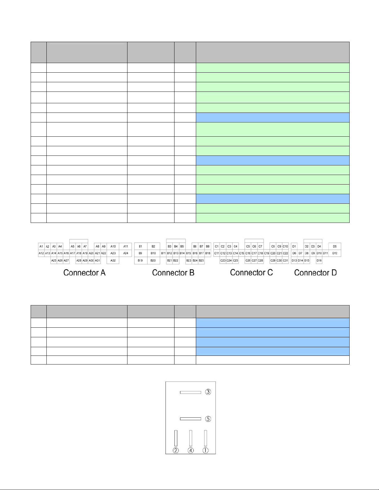
Relay pinout
Pin Relay pinout Destination
1 +12V switched input Stock ECU E9 Input Dedicated
2 Ground Stock ECU A5 Input Dedicated
3 Ground to +5V line AEM EMS D6 Output Dedicated, used to power AEM EMS off properly
4 Ground Stock ECU A5 Input Dedicated
5 -- -- -- Not used
Relay
I/O
Relay pin description
Wire view of relay
Page 20 of 21
Page 21

AEM Electronics Warranty
Advanced Engine Management Inc. warrants to the consumer that all AEM Electronics products will
be free from defects in material and workmanship for a period of twelve months from date of the
original purchase. Products that fail within this 12-month warranty period will be repaired or
replaced when determined by AEM that the product failed due to defects in material or
workmanship. This warranty is limited to the repair or replacement of the AEM part. In no event
shall this warranty exceed the original purchase price of the AEM part nor shall AEM be responsible
for special, incidental or consequential damages or cost incurred due to the failure of this product.
Warranty claims to AEM must be transportation prepaid and accompanied with dated proof of
purchase. This warranty applies only to the original purchaser of product and is non-transferable. All
implied warranties shall be limited in duration to the said 12-month warranty period. Improper use or
installation, accident, abuse, unauthorized repairs or alterations voids this warranty. AEM disclaims
any liability for consequential damages due to breach of any written or implied warranty on all
products manufactured by AEM. Warranty returns will only be accepted by AEM when accompanied
by a valid Return Merchandise Authorization (RMA) number. Product must be received by AEM
within 30 days of the date the RMA is issued.
Please note that before AEM can issue an RMA for any electronic product, it is first necessary for
the installer or end user to contact the tech line at 1-800-423-0046 to discuss the problem. Most
issues can be resolved over the phone. Under no circumstances should a system be returned or a
RMA requested before the above process transpires.
AEM will not be responsible for electronic products that are installed incorrectly, installed in a non
approved application, misused, or tampered with.
Any AEM electronics product can be returned for repair if it is out of the warranty period. There is a
minimum charge of $75.00 for inspection and diagnosis of AEM electronic parts. Parts used in the
repair of AEM electronic components will be extra. AEM will provide an estimate of repairs and
receive written or electronic authorization before repairs are made to the product.
Page 21 of 21
 Loading...