

AEM 30-5135M Analog Oil Metric Pressure Gauge User Manual
AEM Performance Electronics
2205 126th Street Unit A, Hawthorne, CA. 90250
Phone: (310) 484-2322 Fax: (310) 484-0152
http://www.aemelectronics.com
Instruction Part Number: 10-5133 Rev 02
2010 AEM Performance Electronics
Part Number 30-5133
Analog Style 100 PSI Oil/Fuel/Air Pressure Gauge
NOTE: Faceplate Configuration Instructions Included on Separate Sheet
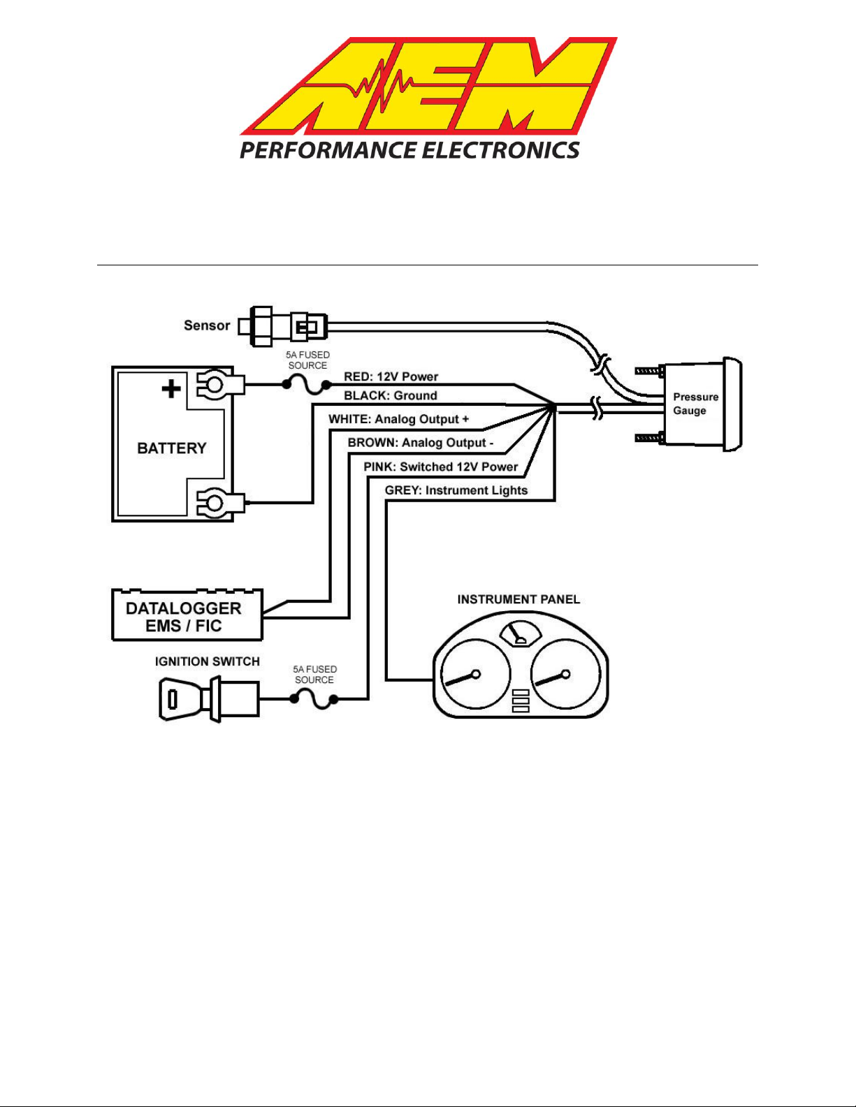
Figure 1. Wiring Schematic
AEM Oil/Fuel Pressure Gauge Parts
1 x 35-5133 Pressure Gauge Assembly
1 x 30-2131-100 Pressure Sensor
1 x 35-4302 Install Kit (6 Butt Connectors)
1 x 10-5133 Installation Instructions
1 x 35-3411 8-Pin Power Harness
1 x 35-3412 3-Pin Sensor Harness
1 x 35-8529S Silver Bezel
1 x 35-8540W Oil Pressure Faceplate, White
1 x 35-8543B Fuel Pressure Faceplate, Black
1 x 35-8543W Fuel Pressure Faceplate, White
1 x 35-8549W Air Pressure Faceplate, White
1 x 35-8549B Air Pressure Faceplate, Black
1 x Faceplate Configuration Instructions
1 x Paper Clip Needle Removal Tool

INSTALLATION
1. Disconnect the negative battery cable.
2. Secure the gauge in a 2 1/16th” (52MM) mounting hole with the supplied bracket.
3. Plug the 8-wire power harness into the mating connector on the back of the
gauge and connect the wires as shown in Figure 1. Note: the locating tabs on
the side of the connector should be nearest the center of the gauge.
4. Thread the sensor into a suitable pressure port that has 1/8” NPT female
threads. Note: a small amount of thread sealant may be used.
5. Connect the sensor to the gauge using the 3-wire sensor cable. The single-row
connector connects to the back of the gauge. The locating tabs on the singlerow connector should be nearest the center of the gauge.
6. Reconnect the negative battery cable.
RED (Power)- Connect to a constant 12 volt power source utilizing a 5A fuse.
BLACK (Ground) – Connect to a clean power ground.
PINK (Switched Power) – Connect to a switched 12 volt power source utilizing a 5A
fuse.
GREY (Lighting Intensity) - Connect to instrument lighting circuit supply voltage.
*WHITE (Analog Output) - Connect to Analog + Input.
*BROWN (Analog Ground) - Connect to Analog – input. (Must be connected if Analog +
is used)
*optional – only needed if using the available differential analog output
Wiring notes:
RED - When wired as shown above, the gauge will park the needle against the
needle stop upon powering down. Alternatively, the RED wire can be connected to the
same location as the PINK wire. With the RED wire and the PINK wire connected to the
same switched power, the needle will remain at its current position upon powering
down. For both power connection methods, the needle will rotate to the parked position
before rotating to the value of the current operating condition upon powering up.
GREY – The GREY wire is used to control the lighting intensity of the gauge.
Maximum lighting intensity is achieved when the GREY wire is connected to 12 volts.
Minimum lighting intensity is achieved when the GREY wire is not connected. The
instrumentation illumination on many vehicles is controlled by varying the supply voltage
to the instrument panel lights. When the GREY wire is connected to the instrument
panel supply voltage, the intensity of the gauge is controlled by the dimmer switch on
the dash.
WHITE – The WHITE wire should be connected to the Analog + input on the
AEM EMS or the analog + input on a similar device.
BROWN – The BROWN wire should be connected to the Analog – input. If the
EMS or similar device does not have a – input, the BROWN wire should be connected
to a sensor ground. If no sensor ground is available, the BROWN wire should be
connected to a power ground. Note: The BROWN wire must be connected in order
to get correct readings from the analog output.
Page 2
 Loading...