

AEM 30-5131M Analog EGT Metric Gauge User Manual
AEM Performance Electronics
2205 126th Street Unit A, Hawthorne, CA. 90250
Phone: (310) 484-2322 Fax: (310) 484-0152
http://www.aempower.com
Instruction Part Number: 10-5131 Rev 04
2009 AEM Performance Electronics
Part Number 30-5131
Analog EGT Gauge
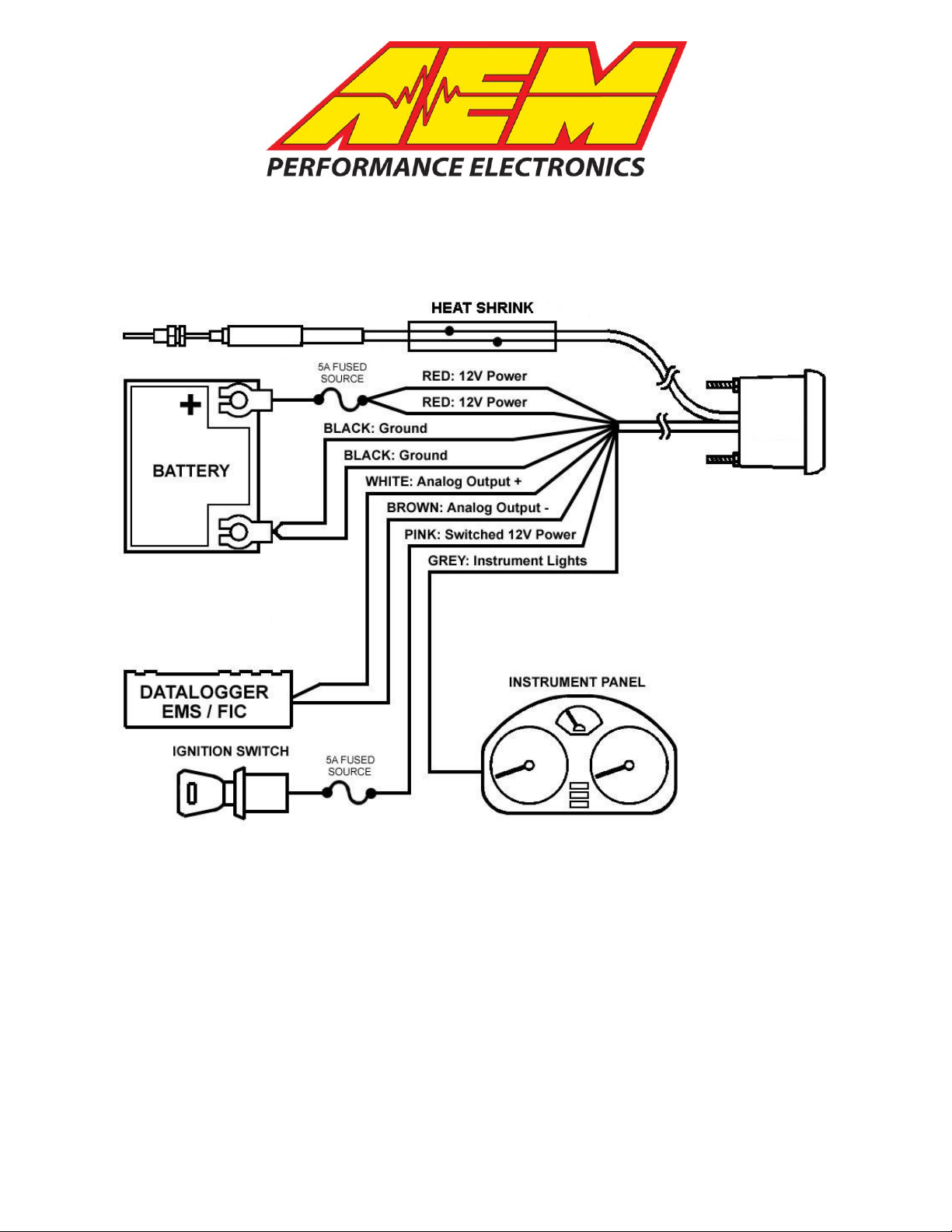
Figure 1. Wiring Schematic
AEM EGT Gauge Parts
1 x 35-5131(B/W) EGT Gauge Assembly
1 x 30-2065 EGT Sensor Thermocouple w/Mount
1 x 35-4302 Install Kit (6 Butt Connectors)
1 x 10-5131 Installation Instructions
1 x 35-3411 8-Pin Power Harness
1 x 35-3414 2-Pin Sensor Harness
1 x 35-8529S Silver Bezel
1 x 6” Heat Shrink
2 x 4-40 Hex Nut
2 x 4-40 Screw

INSTALLATION
1. Disconnect the negative battery cable.
2. Secure the gauge in a 2 1/16th” (52MM) mounting hole with the supplied bracket.
3. Plug the 8-wire power harness into the mating connector on the back of the
gauge and connect the wires as shown in Figure 1. Note: the locating tabs on
the side of the connector should be nearest the center of the gauge.
4. Connect the sensor cable to the gauge. The locating tabs should be closest to
the center of the gauge.
5. Mount the thermocouple as shown in figure 2.
6. Slide the heat shrink tube over the sensor cable and connect the thermocouple to
the cable as shown below in figure 3.
RED - Connect BOTH RED wires to a constant 12 volt power source utilizing a 5A fuse.
BLACK – Connect BOTH BLACK wires to a clean ground.
PINK - Connect to a switched 12 volt power source utilizing a 5A fuse.
GREY - Connect to instrument lighting circuit supply voltage.
*WHITE - Connect to Analog + Input.
*BROWN - Connect to Analog – input. (Must be connected if Analog + is used)
*optional – only needed if using the available differential analog output
Wiring notes:
RED - When wired as shown above, the gauge will park the needle upon
powering down. Alternatively, both RED wires can be connected to a switched, fused
12 volt power source. With both RED wires and the PINK wire connected to switched
power, the needle will remain at its current position upon powering down. For both
power connection methods, the needle will rotate to the parked position before rotating
to the value of the current operating condition upon powering up.
GREY – The GREY wire is used to control the lighting intensity of the gauge.
Maximum lighting intensity is achieved when the GREY wire is connected to 12 volts.
Minimum lighting intensity is achieved when the GREY wire is not connected. The
instrumentation illumination on many vehicles is controlled by varying the supply voltage
to the instrument panel lights. When the GREY wire is connected to the instrument
panel supply voltage, the intensity of the gauge is controlled by the dimmer switch on
the dash.
WHITE – The WHITE wire should be connected to the Analog + input on the
EMS or the analog + input on a similar device.
BROWN – The BROWN wire should be connected to the Analog – input. If the
EMS or similar device does not have a – input, the BROWN wire should be connected
to a sensor ground. If no sensor ground is available, the BROWN wire should be
connected to a power ground. Note: The BROWN wire must be connected in order
to get correct readings from the analog output.
Page 2
Thermocouple Mounting
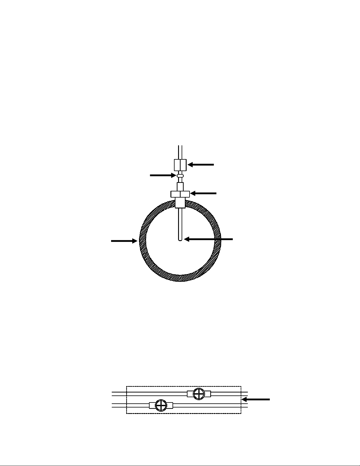
FERRULE SLEEVE
COMPRESSION NUT
THREADED BODY
PIPE/MANIFOLD
WITH 1/8” NPT
THREADS OR
13/32” HOLE
TIP OF THERMOCOUPLE
NEAR CENTER OF
PIPE/MANIFOLD
HEAT SHRINK
Figure 3. Thermocouple to Cable Connection
Figure 2. Thermocouple Mounting
The thermocouple included in the kit comes with a stainless steel compression style
mounting adapter. The mounting adapter consists of three pieces: compression nut,
ferrule sleeve, threaded body. The threaded body has 1/8” NPT male threads. To
install the sensor, the threaded body can either be threaded into a hole with mating 1/8”
NPT threads, or welded to the pipe/manifold. Remove the compression nut, ferrule
sleeve, and thermocouple from the threaded body. For a welded installation, drill a
13/32” hole and weld the threaded body, being careful not to cause any distortion. .
For a threaded installation, either thread the body into an existing hole with 1/8” NPT
threads or drill a hole using an “R” size drill bit and cut the threads using a 1/8” NPT tap.
With the compression nut and ferrule sleeve on the thermocouple, insert the
thermocouple into the threaded body so the tip of the thermocouple is near the center of
the pipe/manifold and tighten the compression nut to the threaded body.
Connecting the Thermocouple
Slide the supplied heat shrink onto the sensor cable. Connect the RED wire from the
thermocouple to the RED wire on the harness and the YELLOW wire from the
thermocouple to the YELLOW wire on the harness using the supplied 4-40 screws and
hex nuts. Make sure the connections are not touching. Center the heat shrink over the
connections and apply mild heat to the heat shrink until it shrinks over the connections.
Page 3
 Loading...