

Page 1

WARNING:
This installation is not for the electronic novice or the PC illiterate!
Instruction Manual
P/N 30-4900 Wideband Failsafe Gauge
Use this system with EXTREME caution! If you are not well versed
in electronics and vehicle instrumentation or are not PC literate,
please do not attempt the installation. Refer the installation to an
AEM trained tuning shop. A list of AEM trained tuning shops is
available at www.aemelectronics.com/dealer_locator.php or by
!
Wideband Failsafe Gauge Parts List
calling 800-423-0046. You should also visit the AEM Performance
Electronics Forum at http://www.aemelectronics.com.
NOTE: AEM holds no responsibility for any engine damage that
results from the misuse of this product!
Qty Description Qty Description
1 Wideband Failsafe Gauge 1 Faceplate, Lambda Black
1 UEGO Sensor 1 Faceplate, Vacuum Black
1 UEGO Harness 1 Harness, Input / Output
1 Install Kit w/ Bung 1 Rubber Band
1 Power Harness 1 Wideband Failsafe Instructions
1 USB Cable 1 Gauge Box
1 Faceplate, AFR White 1 Boost Hose Adapter
1 Faceplate, Boost Black 1 Vacuum Hose, 7/64” ID x 36” L
1 Faceplate, Boost White 1 Silver Bezel
This product is legal in California for racing vehicles only and should never be used on public highways.
AEM Performance Electronics
2205 126th Street Unit A, Hawthorne, CA. 90250
Phone: (310) 484-2322 Fax: (310) 484-0152
http://www.aemelectronics.com
Instruction Part Number: 10-4900 Rev B
2012 AEM Performance Electronics
Page 2
GETTING STARTED
THIS PRODUCT DOES NOT INCLUDE SOFTWARE IN THE PACKAGING. PLEASE DOWNLOAD
AND INSTALL THE WIDEBAND FAILSAFE CONFIGURATION SOFTWARE FROM THE AEM
WEBSITE AT: www.aemelectronics.com/downloads
Alternatively, register on the AEM Electronics Forums at http://forum.aempower.com/forum/index.php
Click on the All Software & Firmware Downloads forum. Click on the AEM Wideband Failsafe Software
link to reach the download page. The most recent software revision will be posted here as well as the link
above. Note that you can subscribe to this thread to be notified when software updates are released. All
current software releases will include a set of revision notes describing feature changes or additions since
the last update.
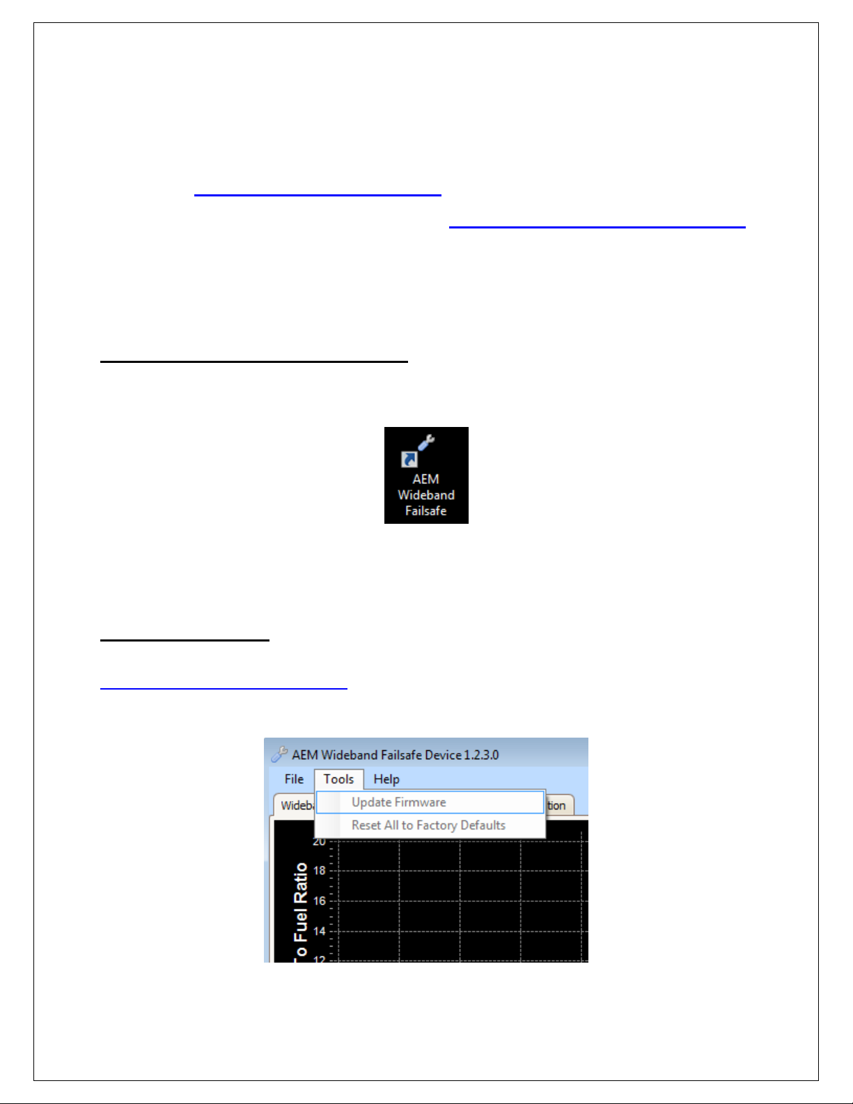
Software Installation Instructions
Follow the Installation Instructions as outlined in the forum post described above. After the software
installation is complete, click on the AEM Wideband Failsafe icon (shown below) to launch the
application.
Connect the USB cable to the PC. The Wideband Failsafe will turn ON with ignition key-on power.
Alternatively, the Wideband Failsafe can be bench-programmed outside of the vehicle without powering it
by connecting just the USB cable. However, the UEGO sensor, MAP sensor, analog outputs, and CAN
outputs will not function.
Firmware Updates
To update the firmware, download the firmware file, if available, from
www.aemelectronics.com/downloads. While connected to the gauge with the USB cable, open the
AEM Wideband Failsafe Software. Go to the Tools drop down menu and select Update Firmware and
follow the on-screen instructions.
Page 3
Page 3
Overview
AEM Wideband Failsafe is an advanced safety device that allows the end user to closely monitor the
performance of their engine. As a tuning tool, this device provides the ability to accurately monitor AFR,
while actively protecting the engine by constantly recording AFR curves and activating a user-defined
failsafe strategy if it runs dangerously lean or excessively rich.
The Wideband FAILSAFE Gauge is a UEGO (Universal Exhaust Gas Oxygen) controller with an internal
boost sensor, an internal data logger and a full color Organic Light Emitting Diode (OLED) display. It
includes technology to activate a failsafe strategy in the event AFR falls outside of a user-defined
operating window. If the AFR falls outside of the set operating window, the Wideband FAILSAFE Gauge
triggers a user defined output function that can save an engine from catastrophic damage.
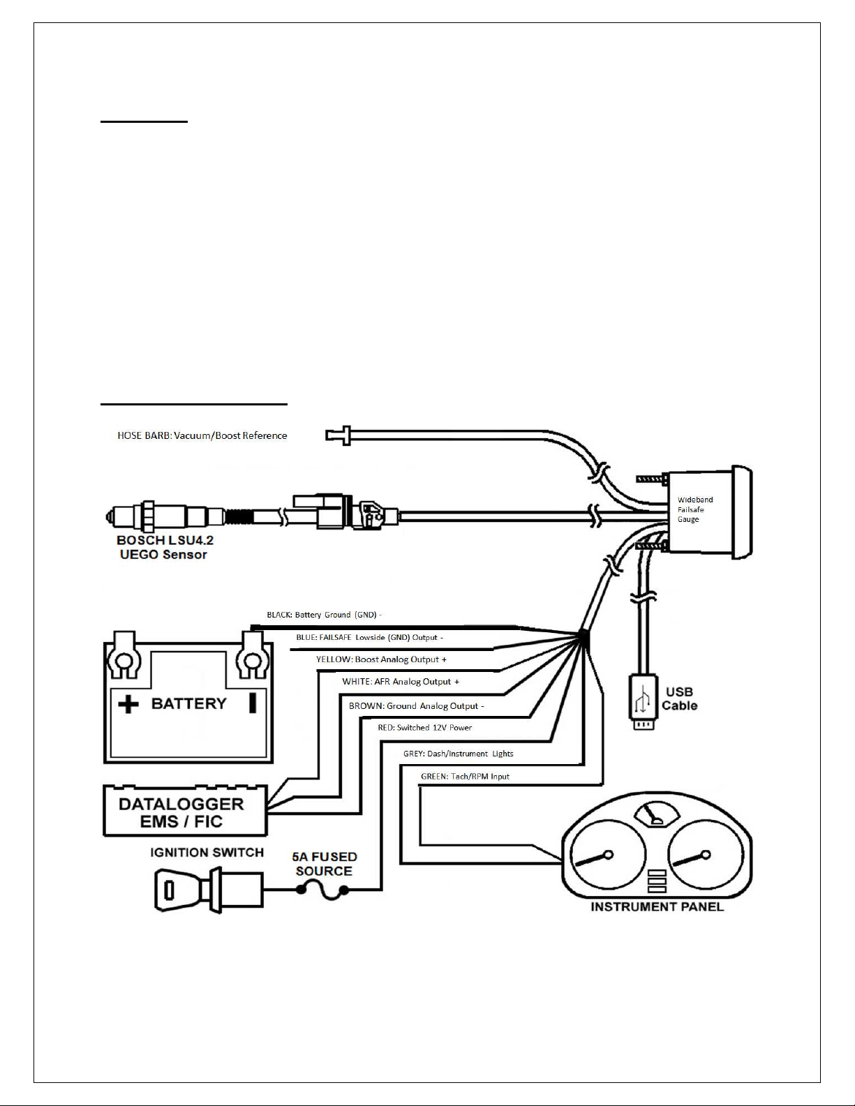
Installation Diagram
Page 4
Page 4
Installation
1. Disconnect the negative battery cable.
2. Temporarily install gauge without bracket into desired mounting location. Gauge mounts into a 2-1/16”
(52MM) hole. The supplied rubber band can be used as a spacer around the gauge if it fits loosely in
mounting hole.
3. Locate a suitable place in the exhaust system to install the included oxygen sensor weld bung. On nonturbocharged engines, mount the oxygen sensor in the exhaust system at least 18 inches downstream
from the exhaust port. On turbocharged engines the oxygen sensor must be installed after the
turbocharger, ideally 18” downstream from the turbocharger exhaust housing. NOTE: If the sensor is
mounted before the turbocharger the pressure differential will affect the accuracy of the unit. For
accurate readings, the sensor must be mounted upstream of the catalytic converters and/or auxiliary air
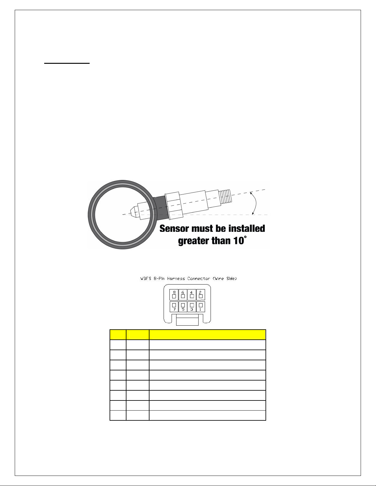
pumps. To prevent collection of liquids between the sensor housing and sensor element during the cold
start phase, the installation angle should be inclined at least 10° from horizontal with the electrical
connection upwards, see image below.
4. Next, the UEGO sensor 8-pin wiring harness should be routed to the oxygen sensor bung.
Pin Color
1 N/C N/C
2 White Heat 3 Orange VM
4 Green IA
5 Red IP
6 Black UN
7 N/C N/C
8 Brown 12V
Description
Page 5
Page 5
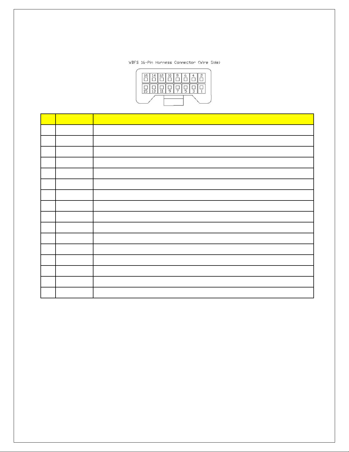
5. Next the main 16-pin connector will be manually wired into the vehicle.
Pin
1 Black Ground; connect to good chassis ground or directly to battery negative (−) terminal
2 Red Ignition power; connect to a fused key on +12V power source
3 Black USB - Dedicated
4 N/C Reserved
5 Red USB - Dedicated
6 Green USB - Dedicated
7 Blue *OPTIONAL* Ground output; connect to an external auxiliary device (1.5A max current)
8 White USB - Dedicated
9 Green *OPTIONAL* Engine Speed Input; connect to a square wave trigger
10 Gray *OPTIONAL* Gauge backlighting; connect to instrument lighting dimmer wire
11 N/C Reserved
12 N/C** *OPTIONAL* AEMnet 13 N/C** *OPTIONAL* AEMnet +
Color Description
14 Brown *OPTIONAL* Analog ground for AFR and MAP; connect to sensor ground of data logger or EMS
15 White *OPTIONAL* 0-5V analog output for AFR; connect to + analog input of data logger or EMS
16 Yellow *OPTIONAL* 0-5V analog output for MAP; connect + analog input of data logger or EMS
NOTES:
• Pins 14/15 are differential analog outputs. The brown wire should be connected to an analog
ground input for best results. If the EMS, logger or similar device does not have an analog ground
input, the brown wire should be connected to a sensor ground. If no sensor ground is available, the
brown wire should be connected to a power ground. The brown wire must be connected in order to
obtain correct AFR and MAP readings from the analog output(s).
• ** Pins 12/13 are un-populated as delivered. Please order the optional 30-3439 wiring harness to
connect the WBFS gauge to other AEMnet products.
• The WBFS gauge is able to receive RPM CAN data input from an AEM ECUs such as the Series-2.
6. Connect all cables and wiring harnesses to gauge. Fully install gauge into hole using mounting bracket
and nuts.
Page 6
Page 6
7. Install USB cable so the PC end of the cable is easily accessible and route the gauge end of cable to
Description
Button
Description
the gauge mounting location. USB cable is meant to be permanently installed to gauge and left in
vehicle. Stow PC end of cable in location such as glove box or center console, etc.
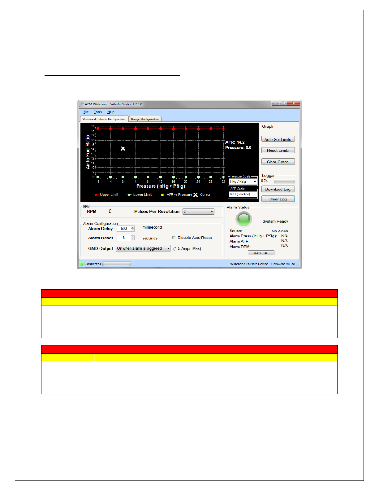
Wideband Failsafe Configuration
In this tab, the AFR monitoring and alarm output functionality of the Wideband Failsafe can be configured.
Air to Fuel Ratio vs. Pressure
Displays AFR vs. Pressure data points. AFR points will be populated live whenever the PC is connected to the
Wideband Failsafe and the UEGO sensor is registering an input. The current AFR and Pressure values are shown
live on the right side of the graph. The graph area is where the high and low AFR limit lines are established.
Configure the pressure scale and AFR scale before setting the boundary lines as they will reset each time a different
scale is selected.
Graph
Auto Set Limits
Reset Limits Resets the upper AFR limit line to maximum and the lower AFR limit line to minimum
Clear Graph
Automatically sets the upper and lower AFR lines based on an average of the collected AFR
data points
Clears all the displayed AFR data points from the graph; does not clear stored AFR data from
logger
Page 7
Page 7
Logger
Button
Description
Parameter
Description
Option
Description
Option
Description
Parameter
Description
Option
Description
Log Percentage Displays current amount of data recorded
Download Log
Clear Log Clears all stored AFR data from the logger
Downloads all the collected AFR data that is stored in the logger; will prompt to save log to disk;
log files saved as .daq for direct viewing in AEMdata program
RPM
RPM Displays the current engine speed dictated by the Pulses Per Revolution option.
Pulses Per
Revolution
Using the RPM parameter, select the number of pulses per revolution to properly calibrate the
engine speed input.
Alarm Configuration
Alarm Delay
Alarm Reset
Disable Auto Reset Select to require power cycle to reset alarm; overrides the automatic alarm reset period.
GND Output
Period of time that measured AFR can be outside the upper and lower AFR limit lines before an
alarm condition is triggered; 100-1000 milliseconds
Period of time AFR must be within the acceptable range before the alarm will automatically
reset and turn OFF; 1-10 seconds
Select to turn the ground output ON or turn the ground output OFF when an alarm is triggered;
1.5 amps max
Alarm Status
Status Indicator Color indicates status; green is system ready, red is alarm triggered
Source
Alarm Press Pressure when alarm was triggered; Units determined by Pressure Scale selection
Alarm AFR AFR when alarm was triggered; Units determined by AFR Scale selection
Alarm Test Simulates the alarm to test output configuration; test duration set by Alarm Delay value
Indicates the source of the alarm condition; possible alarm conditions are high AFR, low AFR,
auxiliary input, and alarm test
Page 8
Page 8

Gauge Configuration
Option
Description
Option
Description
Option
Description
Option
Description
In this tab, the gauge lighting and display features can be configured.
Display Option
Center
Display
Installed
Faceplate
Center display reading configuration; use to select either pressure (InHg / PSIg or Bar) or O2 sensor
(AFR or Lambda)
Faceplate configuration; use to match 24 outer LEDs to faceplate with either Pressure (InHg / PSIg
or Bar) or O2 sensor (AFR or Lambda) [See Appendix II – Changing Faceplate / Bezel]
Alarm Flash
Flash Speed Select speed of flashing while alarm is triggered; flash slow or fast
Dimmer Max Brightness
Dimmer Max
Brightness
Select whether +12V or ground indicates maximum backlighting brightness
Bar-Graph LED Color
RED LED (1) Can be disabled; use slider to configure multiple LEDs. Reference gauge display at bottom right.
ORG LED (2) Can be disabled; use slider to configure multiple LEDs. Reference gauge display at bottom right.
GRN LED (3) Cannot be disabled; use slider to configure multiple LEDs. Reference gauge display at bottom right.
ORG LED (4) Can be disabled; use slider to configure multiple LEDs. Reference gauge display at bottom right.
RED LED (5) Can be disabled; use slider to configure multiple LEDs. Reference gauge display at bottom right.
Page 9
Page 9

Wideband Failsafe Tuning
The following is a basic guideline strategy for configuring the Wideband Failsafe for the first time. The
ideal time to configure the Wideband Failsafe is while the vehicle is being dyno tuned. Ensure your
engine is fully functional mechanically before starting to configure the Wideband Failsafe!
1. In the Wideband Failsafe Configuration tab, click Clear Graph and Reset Limits to zero all settings.
2. If a boosted pressure scale is selected, there will be a pink triangular cursor on the left side of the
graph when the engine is in high vacuum, as shown below. The upper and lower limits for this high
vacuum area will use the lowest pressure (furthest left) breakpoint for alarm triggering.
Page 10
Page 10

3. Run the engine as you would normally drive the vehicle then complete a series of long sweeping high
load 3rd and 4th gear pulls going from low to high RPM each time to populate the graph with AFR data.
Avoid making quick hard pulls as this may skew the AFR data points. Repeat this procedure until a
baseline AFR curve is established. Note: You may notice that a few random AFR data points are
plotted well outside of the normal AFR curve. This is caused by dynamic tip-in wall wetting in transient
pressure situations. This is normal behavior and false triggers can be ignored in the configuration
setup process below.
Page 11
Page 11

4. With a baseline AFR curve now established, click on Auto Set Limits and the software will
produce its best suggested high and low AFR limit lines based on the populated AFR data shown
on the graph. Review and adjust the high and low AFR limit lines as needed to contour the lines
around the baseline AFR curve (shown below). This can be done by clicking on a breakpoint and
either dragging up or down with the mouse or by clicking the up and down arrows on the
keyboard. To move to the next breakpoint, click on it with the mouse or use the right and left
arrows. Pressing the Tab key will toggle back and forth between the high and low limit lines.
5. Test the configuration using your anticipated normal operating conditions with varying engine speed
and engine load situations to account for starting, stopping, accelerating, high boost, low boost, tip in,
fast shifts, slow shifts, etc. If false triggers occur, either adjust the high or low AFR curve up or down
at the pressure breakpoint where the alarm occurred or adjust the Alarm Delay setting.
NOTE: There are two general configuration strategies to follow when using the Wideband Failsafe. The
high and low AFR limit lines can be set very tightly to the baseline AFR curve and a longer Alarm Delay
can be used. Conversely, the high and low AFR limit lines can be set further way from the baseline AFR
curve and a shorter Alarm Delay can be used. Furthermore, many tuners may conclude that a rich AFR
is more acceptable for, safety measures, than a lean AFR. If true, a looser tolerance can be put into the
lower limit line as depicted in the graph above. Only thorough configuration testing will reveal which
strategy is best for your application.
Page 12
Page 12

Data Logger
The Wideband Failsafe has an internal logger that can store approximately 2.5 hours of data. The
system maintains two levels of data logs. First, all AFR data points are stored and downloadable for
viewing on the AFR vs. Pressure Graph in the Wideband Failsafe Configuration tab. Second, all inputs,
outputs, and alarm triggers are logged in special log file format for viewing with the AEMdata software
that comes as part of the Wideband Failsafe download package. Once the logger memory has filled up,
the logger will begin to loop log and the oldest data will be discarded as new data is collected (data points
that were collected will slowly start disappearing). The following is a basic guideline on how to use the
internal data logger. NOTE: The internal data logger is always running when 12V is present.
1. Connect USB cable to PC.
2. In the Wideband Failsafe Configuration tab under Logger, click Download Log. All logged
AFR data points will now be displayed in the AFR vs. Pressure Graph.
3. To download the log to the PC, click YES when prompted to save data to disc and then save
log in desired location.
4. Click YES when prompted to open file in AEMdata.
5. The saved data log will now open as shown below.
Page 13
Page 13

Plot One
Parameter
Description
Parameter
Description
Parameter
Description
AFR Current measured AFR (Gasoline)
AFR Upper Limit Current upper AFR limit value as set from the Wideband Failsafe Configuration tab
AFR Lower Limit Current lower AFR limit value as set from the Wideband Failsafe Configuration tab
Plot Two
Manifold Pressure Current measured Manifold Pressure in PSIg
Engine Speed Current measured RPM, if connected and used
Plot Three
Alarm Source
Alarm Status Indicates state of alarm; 1-alarm triggered, 0-alarm not triggered
Alarm Reset Limit Alarm Reset value
Alarm Reset
Counter
Alarm Delay Limit Alarm Delay value
Alarm Delay
Counter
Indicates what triggered the alarm condition; 3-low AFR condition, 5-high AFR condition, 3auxiliary input, 9-alarm test
Counts up from zero to Alarm Reset value once AFR has returned into the acceptable range
Counts up from zero to Alarm Delay value when AFR occurs outside the high or low AFR
limits; once full Alarm Delay value is reached the alarm will trigger; counter will reset back to
zero if AFR returns back into the acceptable range once count up has began
AEM EMS Series 1 / Series 2 Parameters
Below is the Wideband Failsafe related parameter names found in the AEM EMS Series 1 & 2
programmable ECU software when using the AEMNet daisy-chain. Note the slight difference in
nomenclature used with the AEM Wideband Gauge. Use the descriptions listed above for detailed
information.
AEM Wideband Failsafe Gauge Name AEM EMS Series 1/Series 2 Name
AFR [AFR Gasoline] WBFS AFR
AFR Upper Limit [AFR Gasoline] WBFS Up Limit
AFR Lower Limit [AFR Gasoline] WBFS Low Limit
Manifold Pressure [psi] WBFS Boost
Engine Speed [rpm] WBFS RPM
Alarm Status WBFS Alarm
Alarm Reset Limit [ms] WBFS Alarm Rst Lmt
Alarm Reset Counter [ms] WBFS Alarm Rst Cnt
Alarm Delay Limit [ms] WBFS Alarm Dly Lmt
Alarm Delay Counter [ms] WBFS Alarm Dly Cnt
Alarm Status WBFS Status
Page 14
Page 14

Function
Description
Output Configuration
The Wideband Failsafe has one ground (low side) output that is triggered when an alarm condition exists.
This output can be used in a multitude of ways to reduce boost, retard ignition timing, or otherwise protect
an engine in the event there is a problem with the fuel system. The following is an index of possible
auxiliary devices that can be triggered by the alarm output:
AEM EMS
Nitrous Fuel &
Ignition Maps
Boost Switch Use the ground output to trigger the boost switch; a lower boost value can be targeted
Two-Step Use the ground output to trigger the two-step; a lower engine rev limit can be selected
Use the ground output to trigger the nitrous fuel and ignition maps; ignition timing can be
reduced and fuel can be added
MSD Ignition Products
Product Description
Brown wire: use a relay to apply +12V to trigger ignition interrupt
DIS2 (62112)
DIS4 (62152)
6AL-2 (6421) Blue wire: use a relay to apply +12V to trigger two step
Programmable
6AL-2 (6530)
Digital 6 Plus (6520)
Start/Retard Control (8982) Violet wire: use a relay to apply +12V to trigger timing retard
Timing Controller (8980) Grey wire: ground input to trigger timing retard
Blue wire: use a relay to apply +12V to trigger two step
Pink wire: use a relay to apply +12V to trigger timing retard
Brown wire: use a relay to apply +12V to trigger ignition interrupt
Blue wire: use a relay to apply +12V to trigger two step
Pink wire: use a relay to apply +12V to trigger timing retard
Dark blue wire: use a relay to apply +12V to trigger launch rev limit
Light blue wire: use a relay to apply +12V to trigger burn out rev limit
Pink wire: use a relay to apply +12V to trigger timing retard
Blue wire: use a relay to apply +12V to trigger two step
Pink wire: use a relay to apply +12V to trigger timing retard
Warning Light
The Wideband Failsafe can also be used to directly activate a warning light (Autometer PN 3239 or
similar). Connect the warning light’s white wire to 12V and the low side output to the warning light’s black
(ground) wire to turn the light ON. NOTE: High current lights will require a relay to be installed.
Page 15
Page 15

NC/NO Relay
The following are examples of how a NC/NO relay (Bosch PN 0-332-019-203 or similar) can be
configured for use with the Wideband Failsafe.
Signal Interrupt: The low side (ground) output from the Wideband Failsafe can be used to turn ON a NC
(normally closed) relay and interrupt the output signal from a boost controller to its boost solenoid (shown
below). NOTE: Be sure that pulling power from the boost solenoid will decrease boost down to the
wastegate spring pressure rather than increase boost to the turbochargers max. This will depend on what
type of wastegate is used and how it is plumbed with vacuum hose.
Auxiliary Device: The low side (ground) output from the Wideband Failsafe can be used to turn ON a NO
(normally open) relay and activate or deactivate an auxiliary device that can be used to reduce timing or
boost or control some other function when the current requirement is greater than 1.5 amps.
Page 16
Page 16

Appendix I - Analog Outputs
Voltage
Pressure (psig)
Pressure (Bar)
Pressure (kPA)
Voltage
AFR (Gas)
AFR (Lambda)
There are 2 analog outputs from the Wideband Failsafe; Pressure (MAP) and AFR (O2). These outputs
are both linear DC voltage signals that vary with Pressure or AFR. These signals are used for sending
information to a data logger or an engine management system such as an AEM EMS, AEM F/IC, AEM
Infinity, etc.
Pressure Output Transfer Function
Pressure (psig) = (10 * Volts) – 16
0.5 -11 0.25 25
1.0 -6 0.59 59
1.5 -1 0.94 94
2.0 4 1.28 128
2.5 9 1.63 163
3.0 14 1.97 197
3.5 19 2.32 232
4.0 24 2.66 266
4.5 29 3.01 301
AFR Output Transfer Function
AFR (Gas) = (2.375 * Volts) + 7.3125
0.5 8.50 0.58
1.0 9.69 0.66
1.5 10.88 0.74
2.0 12.06 0.82
2.5 13.25 0.91
3.0 14.44 0.99
3.5 15.63 1.07
4.0 16.81 1.15
4.5 18.00 1.23
Page 17
Page 17

Appendix II - Changing Faceplate / Bezel
The Wideband Failsafe gauge comes with the black bezel and Air/Fuel-Gasoline faceplate installed.
However, a silver bezel and multiple faceplates are also included. To change them, orient the gauge so
you are looking at the faceplate. Rotate the bezel counter-clockwise to unscrew it from the gauge cup.
The bezel, lens, and rubber spacer are all removable. Next, remove the faceplate, but note the two
keyways on each side. When inserting the new faceplate be cognizant of these keyways and line them up
before reassembling.
When reassembling the gauge, it may be necessary to apply a light amount of pressure on the lens and
spacer to keep the faceplate from rotating when reinstalling the bezel. Do not over-tighten the bezel
when reassembling the gauge.
Page 18
Page 18

Appendix III - AEMnet
The following instructions describe the proper installation of the optional AEMnet Harness (30-
3439), which is used to connect the Wideband Failsafe AEMnet communication lines to a second
(or multiple) AEMnet device(s).
1. Disconnect the Wideband Failsafe 16-pin harness connector from the Wideband Failsafe gauge. The
harness connector has a latch on the bottom side that needs to be squeezed as the connector is
lightly freed from the gauge. Refer to Figure 1 below.
Figure 1
2. Locate the green and white pre-crimped terminals on the end of the AEMnet Harness. Figure 2 below
shows the Wideband Failsafe connector and pinout including the green and white leads from the
AEMnet harness.
Figure 2
3. Before inserting the terminals into the connector, refer to Figure 3 to be sure that the locking
mechanism on the terminals is positioned properly in the connector.
Figure 3
Page 19
Page 19

4. Insert the AEMnet+ terminal (white wire) into the available Pin 13 on the Wideband Failsafe
connector. Push the wire in until the locking mechanism on the terminal and connector lock into
place. Pull lightly on the white wire to confirm the locking mechanism has latched. Figure 4 below
shows the correct placement of the AEMnet+ terminal.
Figure 4
5. Insert the AEMnet- terminal (green wire) into the available Pin 12 on the Wideband Failsafe
connector. Push the wire in until the locking mechanism on the terminal and connector lock into
place. Pull lightly on the green wire to confirm the locking mechanism has latched. Figure 5 below
shows the correct placement of the AEMnet- terminal.
Figure 5
6. Connect the Deutsch connector on the opposite end of the AEMnet harness to a mating Deutsch
connector on a second device with AEMnet capabilities. The AEMnet harness includes a male and
female Deutsch connector, allowing AEMnet devices to be daisy-chained together.
Page 20
Page 20

AEMnet Messages
Message
Message
Message
0x00000026 (29-bit)
Rate: 10mS continuous
Byte Label Data Type Scaling Offset Range
0
1
2
3
4
5
6 (bit0)
6 (bit1)
6 (bit2)
6 (bit3)
6 (bit4)
6 (bit5)
6 (bit6)
6 (bit7)
7 (bit0)
7 (bit1)
7 (bit2)
7 (bit3)
7 (bit4) --- --- --- --- --7 (bit5) --- --- --- --- --7 (bit6) --- --- --- --- --7 (bit7) --- --- --- --- ---
AFR Heater Time-Out Error
Lambda 16 bit unsigned .0001 Lambda/bit 0 0 to 6.5535 Lambda
Pressure 16 bit unsigned .001 PSI/bit -15 -15 to 50.535 PSI
RPM 16 bit unsigned .39063 RPM/bit 0 0 to 25,600 RPM
AFR Ready
AFR Heater Open Error
AFR CJ125 Error
AFR Sensor Heating Up
AFR Low Voltage
AFR Heater Short Error
AFR Overtemp Error
Alarm Status
Alarm Source
Alarm Source
Alarm Source
Boolean 0 = false, 1 = true 0 0/1
Boolean 0 = false, 1 = true 0 0/1
Boolean 0 = false, 1 = true 0 0/1
Boolean 0 = false, 1 = true 0 0/1
Boolean 0 = false, 1 = true 0 0/1
Boolean 0 = false, 1 = true 0 0/1
Boolean 0 = false, 1 = true 0 0/1
Boolean 0 = false, 1 = true 0 0/1
Boolean 0 = false, 1 = true 0 0/1
Boolean 0 = false, 1 = true 0 0/1
Boolean 0 = false, 1 = true 0 0/1
Boolean 0 = false, 1 = true 0 0/1
0x00000027 (29-bit)
Rate: 10mS continuous
Byte Label Data Type Scaling Offset Range
0
1
2
3
4
5
6
7
Lambda Upper Limit 16 bit unsigned .0001 Lambda/bit 0 0 to 6.5535 Lambda
Lambda Lower Limit 16 bit unsigned .0001 Lambda/bit 0 0 to 6.5535 Lambda
Alarm Delay Limit 16 bit unsigned 1 mS/bit 0 0 to 65,535 mS
Alarm Delay Counter 16 bit unsigned 1 mS/bit 0 0 to 65,535 mS
0x00000028 (29-bit)
Rate: 10mS while in alarm mode, not transmitted otherwise
Byte Label Data Type Scaling Offset Range
0
1
2
3
4
5
6
7
Alarm Lambda 16 bit unsigned .0001 Lambda/bit 0 0 to 6.5535 Lambda
Alarm Pressure 16 bit unsigned .001 PSI/bit -15 -15 to 50.535 PSI
Alarm Reset Limit 16 bit unsigned 1 mS/bit 0 0 to 65,535 mS
Alarm Reset Counter 16 bit unsigned 1 mS/bit 0 0 to 65,535 mS
Page 21
Page 21

12 Month Limited Warranty
Advanced Engine Management, Inc. warrants to the consumer that all AEM High Performance products will be free
from defects in material and workmanship for a period of twelve (12) months from date of the original purchase.
Products that fail within this 12 month warranty period will be repaired or replaced at AEM’s option, when determined
by AEM that the product failed due to defects in material or workmanship.
This warranty is limited to the repair or replacement of the AEM part. In no event shall this warranty exceed the
original purchase price of the AEM part nor shall AEM be responsible for special, incidental or consequential
damages or cost incurred due to the failure of this product.
Warranty claims to AEM must be transportation prepaid and accompanied with dated proof of purchase. This
warranty applies only to the original purchaser of product and is non-transferable. All implied warranties shall be
limited in duration to the said 12 month warranty period. Improper use or installation, accident, abuse, unauthorized
repairs or alterations voids this warranty.
An AEM Warranty Claim Form Must Accompany All Warranty Claims. Products returned to AEM with no
Return Goods Authorization and or No Warranty Claim Form may be rejected and returned to sender.
AEM disclaims any liability for consequential damages due to breach of any written or implied warranty on all
products manufactured by AEM. Warranty returns will only be accepted be AEM when accompanied by a valid
Return Goods Authorization (RGA) number. Credit for defective products will be issued pending inspection. Product
must be received by AEM within 30 days of the date RGA was issued.
Please note that before we can issue an RGA for any product, it is first necessary for the installer or end user
to contact our EMS tech line at (800) 423-0046 to discuss the problem. Most issues can be solved over the
phone. Under no circumstances should a product be returned or RGA requested before the above process
transpires.
AN AEM WARRANTY CLAIM FORM MUST ACCOMPANY ALL ELECTRONICS WARRANTY CLAIMS. AEM
ELECTRONIC Products returned to AEM with no RGA and or No Warranty Claim Form may be rejected and
returned to sender.
A copy of the AEM Warranty Claim Form can be e-mailed or faxed by contacting (310) 484-2322 and ask for
Warranty/Claims Department.
Need additional help? Contact the AEM Performance Electronics tech
department at 1-800-423-0046 or tech@aempower.com, or visit the AEM
Performance Electronics forum at: http://forum.aempower.com/forum/
Page 22
 Loading...