

Page 1
WARNING:
!
This installation is not for the electronic novice or the PC illiterate!
Use this system with EXTREME caution! If you are not well versed
in electronics and vehicle instrumentation or are not PC literate,
please do not attempt the installation. Refer the installation to an
AEM trained tuning shop. A list of AEM trained tuning shops is
available at www.aemelectronics.com/dealer_locator.php or by
calling 800-423-0046. You should also visit the AEM Performance
Electronics Forum at http://www.aemelectronics.com.
NOTE: AEM holds no responsibility for any engine damage that
results from the misuse of this product!
Instruction Manual
Infinity Layover Harness
GM LS Engines 24x
This product is legal in California for racing vehicles only and should never be used on public highways.
NOTE: All supplied AEM calibrations, Wizards and other tuning information are offered as potential starting points only. IT IS
THE RESPONSIBILITY OF THE ENGINE TUNER TO ULTIMATELY CONFIRM IF THE CALIBRATION IS SAFE FOR ITS
INTENDED USE. AEM holds no responsibility for any engine damage that results from the misuse or mistuning of this
product!
AEM Performance Electronics
2205 126th Street Unit A, Hawthorne, CA. 90250
Phone: (310) 484-2322 Fax: (310) 484-0152
http://www.aemelectronics.com
Instruction Part Number: 10-3532
2014 AEM Performance Electronics
Page 2
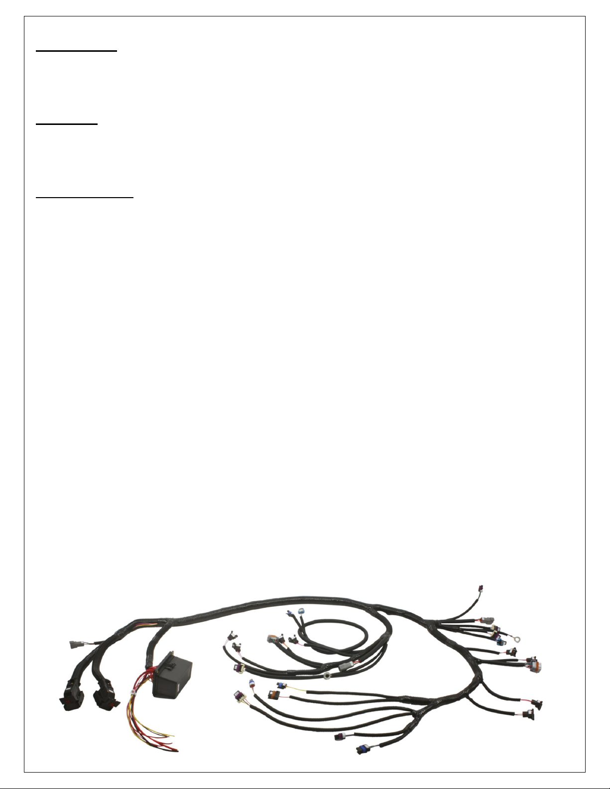
Introduction
This Infinity Layover Harness was designed for the GM LS Engine 24x (manual transmission). The harness includes all
standard GM (or equivalent) connectors for direct plug-in fitment, and requires minimal wiring to complete the Power
Distribution Center (PDC) connections. The Infinity ECU is sold separately, and includes base configuration files for the
GM LS Engines 24x.
Overview
This Instruction Manual describes the harness layout, and provides instructions for installation of the harness on a vehicle.
All included connectors are listed in detail in the provided pinout. Also included are instructions for adding new circuits into
the Infinity connectors if additional sensors or outputs are desired. Please read the entire Instruction Manual prior to
beginning the installation.
Included Items
Connectors
Infinity C1 and C2
8 injectors
2 coil pack connectors, Bank-1 and Bank-2
Oil Pressure sensor
Crank Position Sensor
Cam Position Sensor
Knock connector (supports 2 sensors)
Alternator, 1-wire
Cable Throttle Body
Idle Air Control Valve, 4-wire stepper
UEGO Wideband 02 sensors, Bank-1 and Bank-2
Mass Air Flow sensor
Intake Air Temperature sensor
Engine Coolant Temperature sensor
Manifold Absolute Pressure sensor
Vehicle Speed Sensor
Reverse Lockout Solenoid
Cylinder head grounds, Bank-1 and Bank-2
AEMnet
Power Distribution Center
Bussmann Relay/Fuse Box with flying leads
Relays/Fuses
Relay, ISO 280 Micro Relay 35A/12V (5 ea)
Fuse, Mini ATM 30A (4 ea)
Fuse, Mini ATM 20A (1 ea)
Fuse, Mini ATM 10A (1 ea)
Fuse, Mini ATM 5A (4 ea)
Rev A, 2013/02/05
Page 3
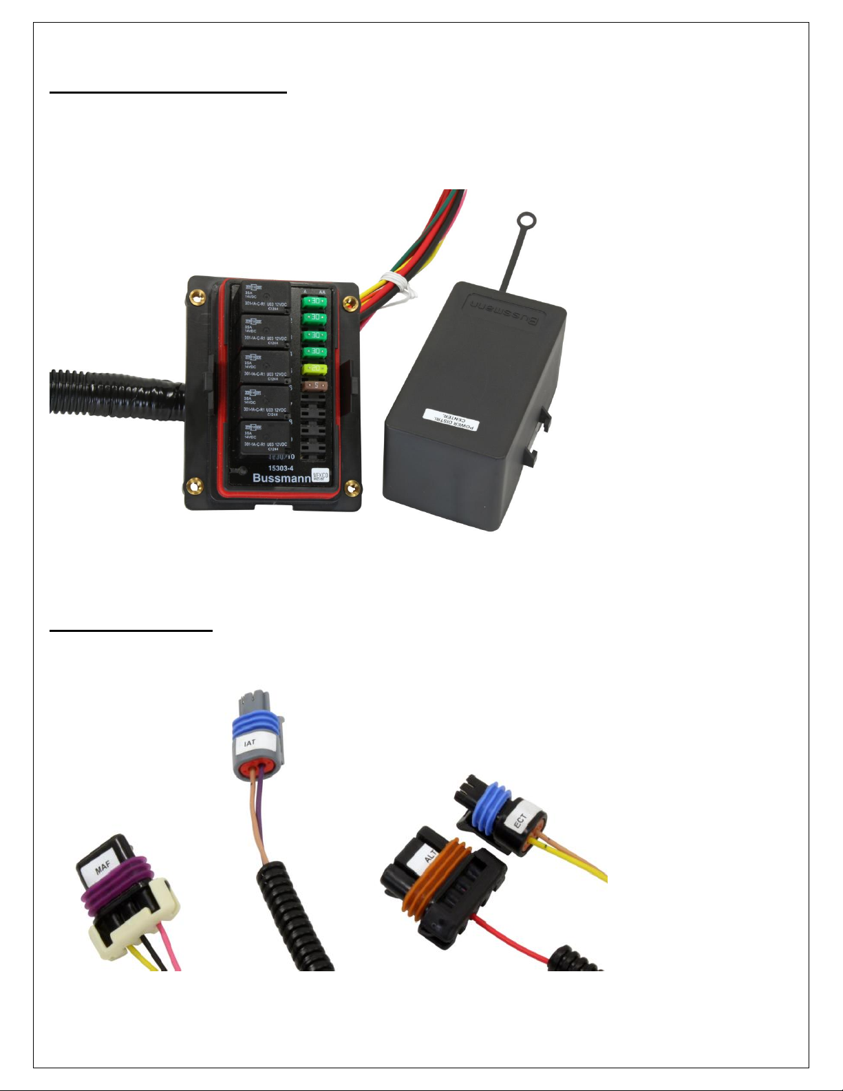
Power Distribution Center
Included in the harness is a Bussmann Power Distribution Center (PDC), pre-populated with the required relays and fuses
for correct operation of the harness. The PDC comes with a bundle of flying leads that need to be properly wired as part of
the installation. Flying leads include switched ignition, battery power and ground, and switched power to Fuel Pump and
Coolant Fans 1 & 2.
Connector Labels
All connectors come labeled to assure proper installation and reduce setup time.
Rev A, 2013/02/05
Page 4
Downloadable Files
The Quickstart Guide and Layover Harness Instruction Manual can be downloaded from www.aemelectronics.com. These
documents are available for download here: www.aemelectronics.com/engine-management-systems-9/infinity-8-10-12-
stand-alone-programmable-ems-90/infinitytuner-software-and-instruction-downloads-92/
Configuration files can be downloaded from www.aeminfinity.com/. An experienced tuner must be available to configure
and manipulate the data before driving can commence
Downloadable files for GM LS Engines 24x
GM_LSX_Supported_Application_v92-20130718RevA.pdf
GM_LSX_24X_Infinity_Layover_Harness_RevA.pdf
7100-XXXX-62 INF-10 Universal v95
7101-XXXX-63 INF-8 Universal v95
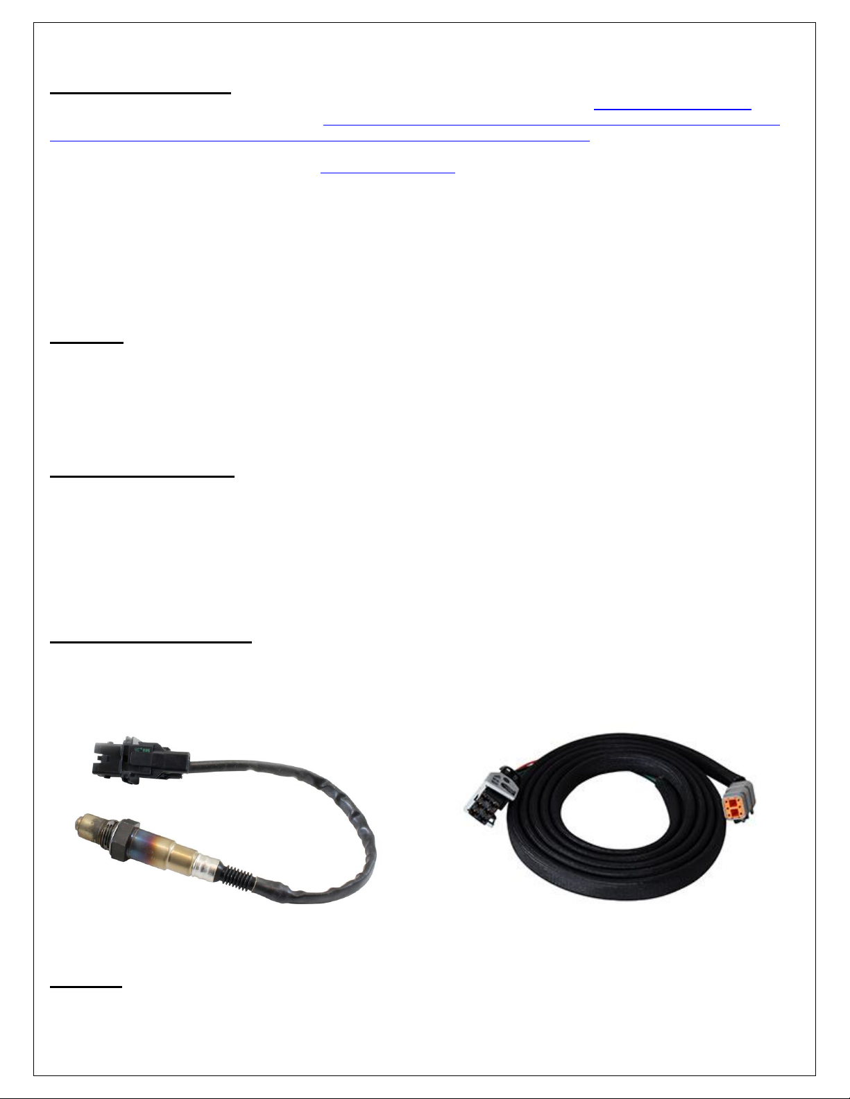
Options
30-2001 UEGO Wideband O2 Sensor
Bosch LSU4.2 Wideband O2 Sensor that connects to AEM 30-3600 UEGO Wideband O2 Sensor Extension Harness
30-3600 UEGO Wideband O2 Sensor Extension Harness
Extension harness to connect AEM UEGO Wideband O2 sensor to 6 pin Deutsch
Cable Throttle Body
The GM LS Engines 24x layover harness is designed for use with a cable throttle body and 4-wire stepper IACV.
However, the Infinity ECU does support up to 2 Drive-By-Wire throttle bodies. Additional wiring can be added into the
Infinity connectors to support Drive-By-Wire throttle bodies if desired. Refer to the included pinout for proper pin numbers.
Drive-By-Wire throttle bodies incorporate idle control into the main throttle body, eliminating the need for a separate Idle
Air Control Valve. If converting to Drive-By-Wire, move the IACV connector branch to a safe location and secure with an
automotive grade tie wrap.
Wideband 02 Sensors
AFR1 (UEGO Sensor Bank 1) and AFR2 (UEGO Sensor Bank 2) plugs are for connecting UEGO wideband Bosch
LSU4.2 sensors (AEM 30-2001) models only. The UEGO extension harness (AEM 30-3600) mates with the layover
harness to the sensor (1 required for each sensor used). Use of any other type of wideband sensor can damage the
sensor and/or the Infinity ECU.
AEMnet
AEMNet is an open architecture based on CAN 2.0 which provides the ability for multiple enabled devices, such as
dashboards, data loggers, etc. to easily communicate with one another through two twisted cables (CAN+/CAN-).
Rev A, 2013/02/05
Page 5

Installation Notes
Wiring Conventions and EMI
The GM LS Engines 24x layover harness comes pre-wired with all connectors, fuses, and relays needed to operate an
engine. However, the PDC does require extension/termination of the flying leads to their appropriate devices, and
additional sensors and other devices can be wired into the harness as needed for the specific application. The following
guidelines should be adhered to while completing the required wiring.
A proper wiring job includes proper termination of the wire at the sensor. The wire terminal end must be moisture tight
where it plugs into the sensor and it must have strong, electrically sound terminals. The preferred method of securing a
wire to a terminal is to use a crimp terminal with NO solder. It is important to use the proper crimping tool for sound
terminal construction. Plastic terminal plugs must have moisture tight seals. Inspect each plug to make sure the seals are
in place. Di-electric grease can be added in the terminal slots to further aid in corrosion resistance.
If a splice into a wire must be made and no solder-less terminals are available, then you must properly solder the splice.
Noise can be a serious problem and can cause intermittent misfiring of the engine. Every precaution should be taken to
prevent interference to the ECU’s operation. Resistive plug leads are REQUIRED. The GM LS Engines 24X Layover
Harness comes with shielded cables for the cam and crank position sensors. These wires have shield grounds that are
grounded at the Infinity ECU plug. They are NOT grounded at the sensor end of the cable. Attempting to ground both
ends of the cable will cause a condition called ground looping and will remove any noise protection the cable has.
To eliminate or reduce the chance of EMI, wires that carry high current must run in twisted pairs. An example of this would
be the power leads from a multiple spark ignition system. These ignition systems can carry up to 100 amps for a couple
milliseconds at the time of discharge, which induces a strong magnetic field in close proximity of the wires.
The routing of the wire loom is critical to EFI system performance and safety. The following safety considerations should
be made when installing the wire loom:
Heat protection: the loom should be placed away from or insulated from sources of heat. The obvious item(s) that
should be avoided are the exhaust manifolds, EGR delivery tubes, and turbochargers. If it is absolutely necessary
to route a wire in close proximity to any of these items, then a suitable insulator must be used.
Noise suppression: do not route wires near the HT leads. For coil-on-plug ignition systems this is not as critical.
Moving component protection: route wires away from moving components such as fans, the blower belt, or the
throttle linkage. Also, make sure the wires are not under any strain when the engine is at full deflection on the
motor mounts.
Never have the wires in exposed bundles throughout the engine compartment.
Determining ECU Location
It is recommended that the ECU be placed in an environment that does not expose it to temperatures above 85°
Celsius (160F).
In cases where the Infinity is to be used in place of the stock ECU, the location that the stock ECU occupied is
suitable.
On applications where the ECU is to be located in a different position than stock, the interior of the vehicle is best.
The Infinity should be located in a place that reduces the length of extension wires from the PDC while
maintaining an environmentally sound location.
The ECU location must permit the PDC to be mounted in a serviceable location.
Power Distribution Center
The PDC contains all of the Relays and Fuses for the entire harness, and should be mounted in a location which permits
serviceability. Ideally the PDC should be located in the passenger compartment, or if necessary within the engine
compartment as far away from heat sources as can be achieved.
The PDC contains the flying lead bundle which must be wired to the battery, fuel pump and radiator fan(s), and switched
ignition. Routing of this flying lead bundle should also be taken into account when determining the mounting location of
the PDC.
Rev A, 2013/02/05
Page 6
Required Wiring
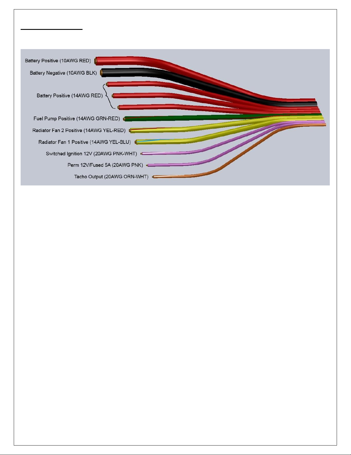
The GM LS Engines 24x Layover Harness comes with a flying lead bundle wired into the PDC. Each of the flying leads
needs to be wired to an appropriate device, or sealed and tied wrapped if not used.
Power and Ground
The Infinity must have an electrically secure ground connection, which means that the battery negative must be
properly grounded to the battery AND the cylinder head grounds muse be properly grounded to the engine. The
ground wires must have perfect electrical conductivity, which means that there must not be any paint or rust under
the wire terminals.
The Battery Negative (10AWG BLK) and Battery Positive (10AWG RED) wires must be extended long enough to
reach the battery without having excess length. A 10AWG or larger gauge wires must be used to make the
extensions.
The 3 Battery Positive (14AWG RED) wires supply power to 3 relays:
1. FPump
2. RadFan1
3. RadFan2
Each 14AWG wire can be extended with a 14AWG or larger gauge wire and connected directly to the battery
positive. Alternatively, the 3 wires can be spliced together with a large enough gauge wire to support the
amperage load of all three devices combined. The amperage load of your Radiator Fans and Fuel Pump is
unique, and the wire gauge selected for your splice must be calculated correctly. Large voltage drops, burned
wire insulation, and fire can occur from using too small of a gauge wire. Reference an American Wire Gauge table
for more details on amperage ratings.
To prevent rust build up, we recommend applying a protective layer of dielectric grease, such as Standard Ignition
SL-4, to the bare metal surface.
Fuel Pump
Run this wire to the fuel pump positive terminal. This wire provides fused/switched power to the fuel pump. A separate
ground wire needs to connect the fuel pump negative terminal to chassis/battery ground.
Radiator Fan 1 Positive
Run this wire to the Radiator Fan 1 positive terminal. This wire provides fused/switched power to the radiator fan. A
separate ground wire needs to connect the radiator fan negative terminal to chassis/battery ground.
Radiator Fan 2 Positive
Run this wire to the Radiator Fan 2 positive terminal. This wire provides fused/switched power to the radiator fan. A
separate ground wire needs to connect the radiator fan negative terminal to chassis/battery ground.
Rev A, 2013/02/05
Page 7
Switched Ignition 12V
The Switched Ignition flying lead (PNK-WHT) must be connected to the output on the ignition switch that supplies 12V
when the switch is in the Start and Run position. The ignition switch output should be isolated, meaning that it is dedicated
to the PNK-WHT wire, and should NOT supply switched ignition power to any other device.
Perm 12V
The Perm 12V/Fused 5A PNK flying lead can be used to power the ignition switch if the switch does not already have a
12V source wired to it.
Tacho Output
The Tacho Output (20AWG ORN-WHT) transmits a 0-12V pulse signal. The Tacho Output can be configured in the
Infinity Tuner Wizard to transmit the desired pulses per engine revolution in order to match the installed tachometer.
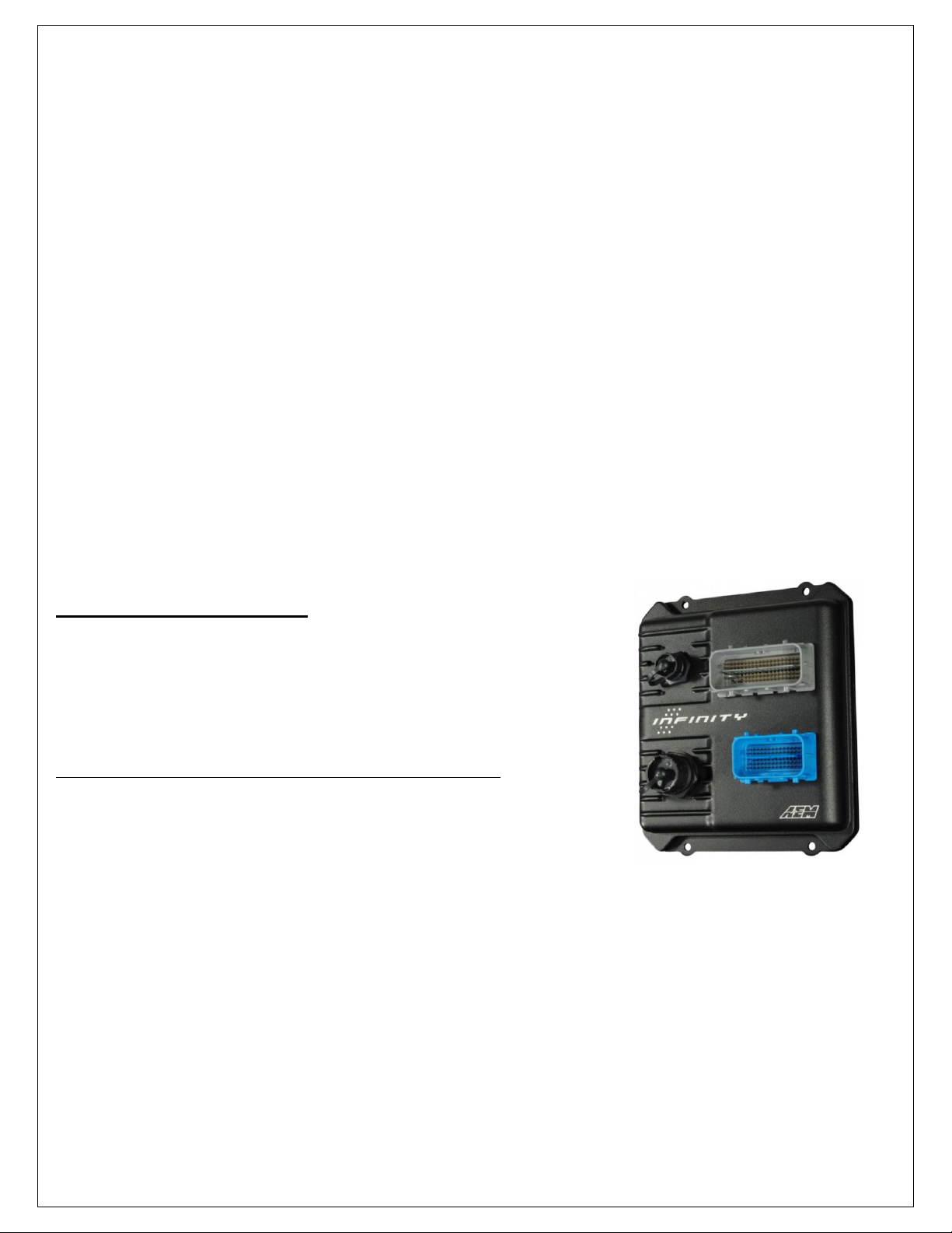
INFINITY CONNECTORS
The AEM Infinity EMS uses the MX123 Sealed Connection System from Molex.
Refer to the 10-7100 for EMS 30-7100 Infinity Quick Start Guide for details on
connector assembly and handling.
AEM strongly recommends that users become familiar with the proper tools and
procedures before attempting any modifications. The entire user manual can be
downloaded direct from Molex at:
http://www.molex.com/mx_upload/family//MX123UserManual.pdf
Rev A, 2013/02/05
Page 8

C1
Infinity Connector C1
73 Way F Receptacle 0.64 2.8 Series Sealed (GY)
Pin
Wire Color
Gauge
Destination
Description
1 2 3 4 5
C1-2
GRN
20
C23-B
---
---
---
---
Reverse Lockout Lowside Driver
C1-4
WHT
18
C26-4
---
---
---
---
Deutsch DTM04-6P UEGO B1-HEAT
C1-5
GRN
20
C26-2
---
---
---
---
Deutsch DTM04-6P UEGO B1-IA
C1-6
RED
20
C26-6
---
---
---
---
Deutsch DTM04-6P UEGO B1-IP
C1-7
BLK
20
C26-1
---
---
---
---
Deutsch DTM04-6P UEGO B1-UN
C1-8
ORN
20
C26-5
---
---
---
---
Deutsch DTM04-6P UEGO B1-VM
C1-10
PNK/RED
20
P1-7A
---
---
---
---
12V Perm Power
C1-11
DK GRN/WHT
20
C4-C
---
---
---
---
Coil 4
C1-12
LT BLU
20
C3-F
---
---
---
---
Coil 3
C1-13
RED/WHT
20
C4-B
---
---
---
---
Coil 2
C1-14
PPL
20
C3-G
---
---
---
---
Coil 1
C1-15
LT BLU/WHT
20
C4-F
---
---
---
---
Coil 6
C1-16
DK GRN
20
C3-C
---
---
---
---
Coil 5
C1-17
VIO
20
P1-5D
---
---
---
---
Radiator Fan 1 Relay Control Lowside
C1-18
VIO/BLK
20
P1-7D
---
---
---
---
Radiator Fan 2 Relay Control Lowside
C1-19
YEL/BLK
20
C17-B
---
---
---
---
Crank Position Sensor Ground
C1-20
PNK/BLK
20
C18-B
---
---
---
---
Cam Position Sensor Ground
C1-21
DK BLU/BLK
20
C17-A
---
---
---
---
Crank Position Sensor Signal
C1-22
BRN/WHT
20
C18-A
---
---
---
---
Cam Position Sensor Signal
C1-24
YEL
20
C14-A
---
---
---
---
Mass Air Flow Sensor Signal
C1-27
DK BLU
20
C20-A
---
---
---
---
Knock Sensor Signal 1
C1-28
LT BLU
20
C20-B
---
---
---
---
Knock Sensor Signal 2
C1-29
YEL/WHT
20, 20
P1-1D
P1-3D
---
---
---
EFI-1 Relay/EFI-2 Relay Control Lowside
C1-30
BRN
20
C3-E
---
---
---
---
Coil Signal Ground (Bank 1)
C1-31
GRN
22
C28-2
---
---
---
---
CAN Low (twisted pair)
C1-32
WHT
22
C28-1
---
---
---
---
CAN High (twisted pair)
C1-34
VIO/WHT
20
P1-9D
---
---
---
---
Fuel Pump Relay Control Lowside
C1-35
DK BLU
20
C16-C
---
---
---
---
Throttle Position Sensor Signal
C1-36
LT GRN
20
C13-B
---
---
---
---
Manifold Absolute Pressure Signal
C1-41
GRY
20
C17-C
---
---
---
---
Crank Position Sensor +5V Supply
C1-42
GRY
20
C18-C
---
---
---
---
Cam Position Sensor +5V Supply
C1-44
RED
20
C21-B
---
---
---
---
12V High Side Driver -> 470Ω -> Alternator
C1-55
MESH
---
C17-M
C18-M
---
---
---
Ground for Cam/Crank wire shieldings (drains)
C1-56
YEL/BLK
20
C10-B
---
---
---
---
Injector 6 Control Lowside
C1-57
BLK/WHT
20
C9-B
---
---
---
---
Injector 5 Control Lowside
C1-58
LT BLU/BLK
20
C8-B
---
---
---
---
Injector 4 Control Lowside
C1-59
PNK/BLK
20
C7-B
---
---
---
---
Injector 3 Control Lowside
C1-60
BLK
20
C28-4
---
---
---
---
AEMnet Ground
C1-61
PNK/YEL
20
SP-4
---
---
---
---
ECU 12V from EFI-1
C1-62
LT GRN/BLK
20
C6-B
---
---
---
---
Injector 2 Control Lowside
C1-63
BLK
20
C5-B
---
---
---
---
Injector 1 Control Lowside
C1-64
PNK/YEL
20
SP-4
---
---
---
---
ECU 12V from EFI-1
C1-65
PNK/WHT
20
1' flying lead for ign switch
12V Switched Ignition
C1-66
YEL
20
C19-B
---
---
---
---
Engine Coolant Temperature Sensor Signal
C1-67
TAN
20
C24-B
---
---
---
---
Intake Air Temperature Sensor Signal
C1-69
LT GRN/WHT
20
C15-B
---
---
---
---
IAC Stepper Motor Coil B High
C1-70
LT BLU/WHT
20
C15-D
---
---
---
---
IAC Stepper Motor Coil A High
C1-71
LT GRN/BLK
20
C15-A
---
---
---
---
IAC Stepper Motor Coil B Low
C1-72
LT BLU/BLK
20
C15-C
---
---
---
---
IAC Stepper Motor Coil A Low
C1-73
BLK
14
SP-1
---
---
---
---
Battery Ground
GM LS Engines 24x Pinout
Rev A, 2013/02/05
Page 9
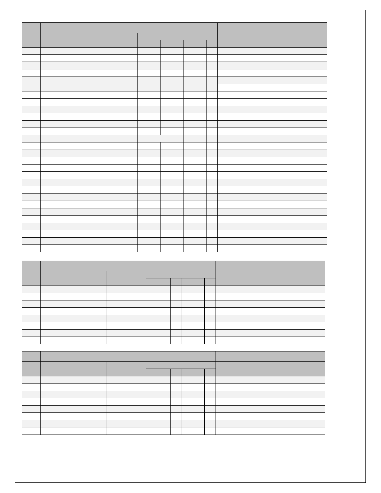
C2
Infinity Connector C2
56 Way F Receptacle 0.64 2.8 Series Sealed (BU)
Pin
Wire Color
Gauge
Destination
Description
1 2 3 4 5
C2-3
BLK
18
SP-1
---
---
---
---
Battery Ground
C2-4
RED/BLK
20
C11-B
---
---
---
---
Injector 7 Control Lowside
C2-5
DK BLU/WHT
20
C12-B
---
---
---
---
Injector 8 Control Lowside
C2-8
BRN
20
C4-E
---
---
---
---
Coil Signal Ground (Bank 2)
C2-9
PNK/YEL
20
SP-4
---
---
---
---
ECU 12V from EFI-1
C2-13
---
---
---
---
---
---
---
Optional Drive-by-Wire (AccPedalPosition-2)
C2-14
---
---
---
---
---
---
---
Optional Drive-by-Wire (AccPedalPosition-1)
C2-18
GRN
20
C25-C
---
---
---
---
AEM Oil Pressure Sensor Signal
C2-21
---
---
---
---
---
---
---
Optional Drive-by-Wire (TPS1B)
C2-22
GRY
20
C13-C
---
---
---
---
MAP Sensor 5V Supply
C2-23
GRY
20
C16-A
---
---
---
---
TPS 5V Supply
C2-24
GRY
20
C25-B
---
---
---
---
Oil Pressure Sensor 5V Supply
C2-29
ORN/WHT
20
1' Flying Lead
---
---
---
Tacho Signal Out (1' flying lead)
C2-30
BLK, PPL
20
C25-A
C24-A
---
---
---
Sensor Ground
C2-31
TAN, BLK
20
C19-A
C16-B
---
---
---
Sensor Ground
C2-32
ORN/BLK
20
C13-A
---
---
---
---
MAP Sensor Ground
C2-34
---
---
---
---
---
---
---
Optional Drive-by-Wire (TPS2A)
C2-36
---
---
---
---
---
---
---
Optional Drive-by-Wire (TPS2B)
C2-39
BLK
18
SP-1
---
---
---
---
Battery Ground
C2-40
BLK
18
SP-1
---
---
---
---
Battery Ground
C2-45
ORN
20
C27-5
---
---
---
---
Deutsch DTM04-6P UEGO B2-VM
C2-46
BLK
20
C27-1
---
---
---
---
Deutsch DTM04-6P UEGO B2-UN
C2-47
RED
20
C27-6
---
---
---
---
Deutsch DTM04-6P UEGO B2-IP
C2-48
GRN
20
C27-2
---
---
---
---
Deutsch DTM04-6P UEGO B2-IA
C2-49
WHT
18
C27-4
---
---
---
---
Deutsch DTM04-6P UEGO B2-HEAT
C2-50
PNK/RED
---
P1-7A
---
---
---
---
12V Perm Power
C2-51
RED
20
C3-B
---
---
---
---
Coil 7
C2-52
PPL/WHT
20
C4-G
---
---
---
---
Coil 8
C3
Coil B1
7 Way F Metri-Pack 150 Series Sealed (Cream)
Pin
Wire Color
Gauge
Destination
Description
1 2 3 4 5
A
BLK
16
SP-1
---
---
---
---
Power Ground
B
RED
20
C2-51
---
---
---
---
IC 7 Control
C
DK GRN
20
C1-16
---
---
---
---
IC 5 Control
D
---
---
---
---
---
---
---
Not Used
E
BRN
20
C1-30
---
---
---
---
Signal Ground
F
LT BLU
20
C1-12
---
---
---
---
IC 3 Control
G
PPL
20
C1-14
---
---
---
---
IC 1 Control
H
PNK
16
SP-5
---
---
---
---
Ignition Voltage
C4
Coil B2
7 Way F Metri-Pack 150 Series Sealed (Cream)
Pin
Wire Color
Gauge
Destination
Description
1 2 3 4 5
A
BLK
16
SP-1
---
---
---
---
Power Ground
B
RED/WHT
20
C1-13
---
---
---
---
IC 2 Control
C
DK GRN/WHT
20
C1-11
---
---
---
---
IC 4 Control
D
---
---
---
---
---
---
---
Not Used
E
BRN
20
C2-8
---
---
---
---
Signal Ground
F
LT BLU/WHT
20
C1-15
---
---
---
---
IC 6 Control
G
PPL/WHT
20
C2-52
---
---
---
---
IC 8 Control
H
PNK
16
SP-6
---
---
---
---
Ignition Voltage
Rev A, 2013/02/05
Page 10

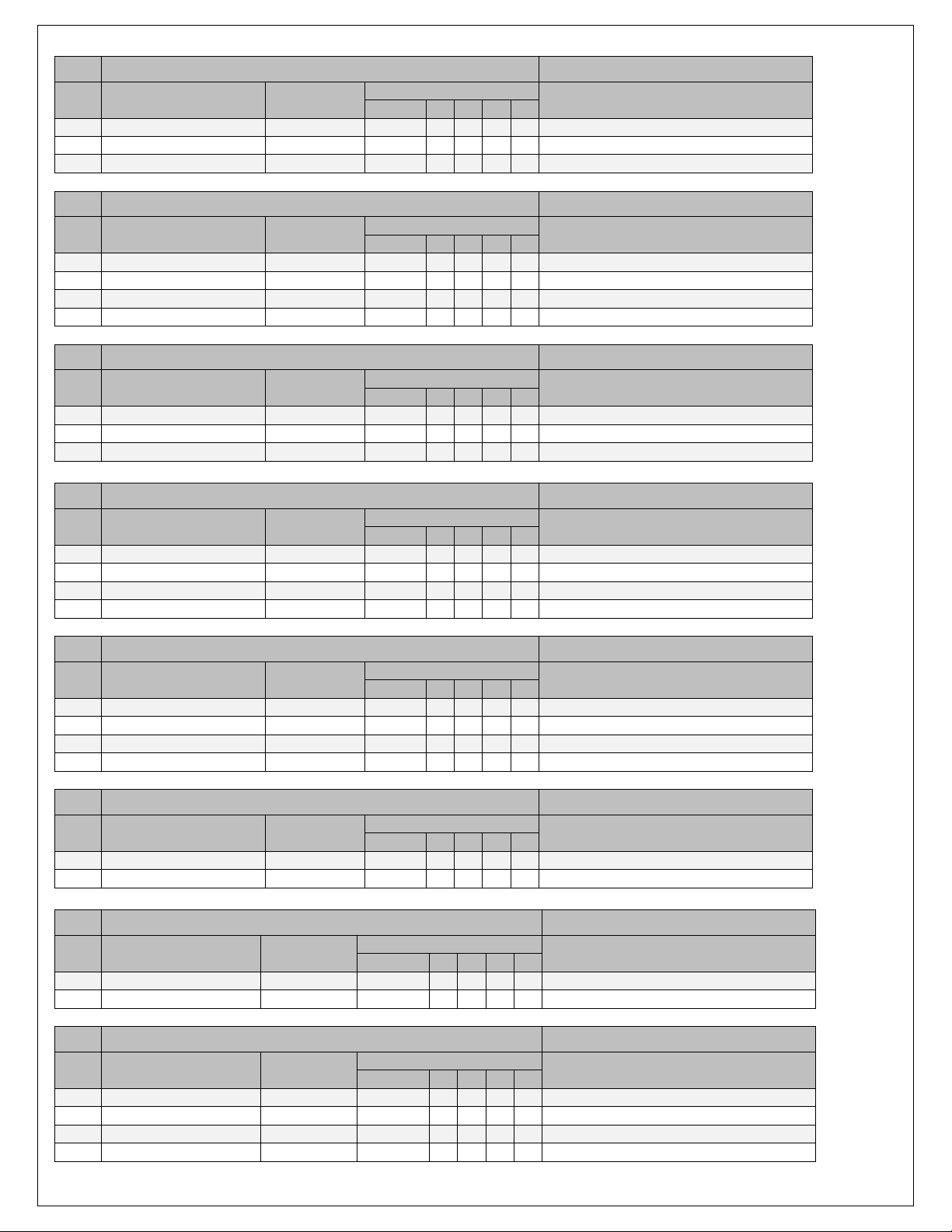
C5
Injector 1
2 Way F Metri-Pack 280.1 Series Pull to Seat (BLK)
Pin
Wire Color
Gauge
Destination
Description
1 2 3 4 5
A
PNK
20
SP-2
---
---
---
---
Ignition Voltage
B
BLK
20
C1-63
---
---
---
---
Fuel Injector 1 Control
C6
Injector 2
2 Way F Metri-Pack 280.1 Series Pull to Seat (BLK)
Pin
Wire Color
Gauge
Destination
Description
1 2 3 4 5
A
PNK
20
SP-3
---
---
---
---
Ignition Voltage
B
LT GRN/BLK
20
C1-62
---
---
---
---
Fuel Injector 2 Control
C7
Injector 3
2 Way F Metri-Pack 280.1 Series Pull to Seat (BLK)
Pin
Wire Color
Gauge
Destination
Description
1 2 3 4 5
A
PNK
20
SP-2
---
---
---
---
Ignition Voltage
B
PNK/BLK
20
C1-59
---
---
---
---
Fuel Injector 3 Control
C8
Injector 4
2 Way F Metri-Pack 280.1 Series Pull to Seat (BLK)
Pin
Wire Color
Gauge
Destination
Description
1 2 3 4 5
A
PNK
20
SP-3
---
---
---
---
Ignition Voltage
B
LT BLU/BLK
20
C1-58
---
---
---
---
Fuel Injector 4 Control
C9
Injector 5
2 Way F Metri-Pack 280.1 Series Pull to Seat (BLK)
Pin
Wire Color
Gauge
Destination
Description
1 2 3 4 5
A
PNK
20
SP-2
---
---
---
---
Ignition Voltage
B
BLK/WHT
20
C1-57
---
---
---
---
Fuel Injector 5 Control
C10
Injector 6
2 Way F Metri-Pack 280.1 Series Pull to Seat (BLK)
Pin
Wire Color
Gauge
Destination
Description
1 2 3 4 5
A
PNK
20
SP-3
---
---
---
---
Ignition Voltage
B
YEL/BLK
20
C1-56
---
---
---
---
Fuel Injector 6 Control
C11
Injector 7
2 Way F Metri-Pack 280.1 Series Pull to Seat (BLK)
Pin
Wire Color
Gauge
Destination
Description
1 2 3 4 5
A
PNK
20
SP-2
---
---
---
---
Ignition Voltage
B
RED/BLK
20
C2-4
---
---
---
---
Fuel Injector 7 Control
C12
Injector 8
2 Way F Metri-Pack 280.1 Series Pull to Seat (BLK)
Pin
Wire Color
Gauge
Destination
Description
1 2 3 4 5
A
PNK
20
SP-3
---
---
---
---
Ignition Voltage
B
DK BLU/WHT
20
C2-5
---
---
---
---
Fuel Injector 8 Control
C13
MAP Sensor
3 Way F Metri-Pack 150 Series (GRY)
Pin
Wire Color
Gauge
Destination
Description
1 2 3 4 5
A
ORN/BLK
20
C2-32
---
---
---
---
Sensor Ground
B
LT GRN
20
C1-36
---
---
---
---
MAP Sensor Signal
C
GRY
20
C2-22
---
---
---
---
5-Volt Reference
Rev A, 2013/02/05
Page 11
C14
MAF Sensor
3 Way F Metri-Pack 150 Series (BLK)
Pin
Wire Color
Gauge
Destination
Description
1 2 3 4 5
A
YEL
20
C1-24
---
---
---
---
MAF Sensor Signal
B
BLK
20
SP-3
---
---
---
---
Ground
C
PNK
20
SP-7
---
---
---
---
Ignition Voltage
C15
Idle Air Control Motor
4 Way F Metri-Pack 150.2 Series Pull to Seat
Pin
Wire Color
Gauge
Destination
Description
1 2 3 4 5
A
LT GRN/BLK
20
C1-71
---
---
---
---
IAC Stepper Motor Coil B LOW
B
LT GRN/WHT
20
C1-69
---
---
---
---
IAC Stepper Motor Coil B HIGH
C
LT BLU/BLK
20
C1-72
---
---
---
---
IAC Stepper Motor Coil A LOW
D
LT BLU/WHT
20
C1-70
---
---
---
---
IAC Stepper Motor Coil A HIGH
C16
Throttle Position Sensor
3 Way F Metri-Pack 150 Series Pull to Seat (BLK)
Pin
Wire Color
Gauge
Destination
Description
1 2 3 4 5
A
GRY
20
C2-23
---
---
---
---
5-Volt Reference
B
BLK
20
C2-31
---
---
---
---
Sensor Ground
C
DK BLU
20
C1-35
---
---
---
---
TPS Sensor Signal
C17
Crank Position Sensor
3 Way F Metri-Pack 150 Series (BLK)
Pin
Wire Color
Gauge
Destination
Description
1 2 3 4 5
A
DK BLU/BLK
20
C1-21
---
---
---
---
CKP Sensor Signal
B
YEL/BLK
20
C1-19
---
---
---
---
Sensor Ground
C
GRY
20
C1-41
---
---
---
---
5-Volt Reference
M
Mesh
---
C1-55
---
---
---
---
Shielding Drain
C18
Cam Position Sensor
3 Way F Metri-Pack 150 Series (BLK)
Pin
Wire Color
Gauge
Destination
Description
1 2 3 4 5
A
BRN/WHT
20
C1-22
---
---
---
---
CMP Sensor Signal
B
PNK/BLK
20
C1-20
---
---
---
---
Sensor Ground
C
GRY
20
C1-42
---
---
---
---
5-Volt Reference
M
Mesh
---
C1-55
---
---
---
---
Shielding Drain
C19
Engine Coolant Temp Sensor
2 Way F Metri-Pack 150.2 Series Sealed P2S (BLK)
Pin
Wire Color
Gauge
Destination
Description
1 2 3 4 5
A
TAN
20
C2-31
---
---
---
---
Sensor Ground
B
YEL
20
C1-66
---
---
---
---
ECT Sensor Signal
C20
Knock Sensors
2 Way F Metri-Pack 150 Series Sealed (BLK)
Pin
Wire Color
Gauge
Destination
Description
1
2 3 4 5 A
DK BLU
20
C1-27
---
---
---
---
Knock Sensor 1 Signal
B
LT BLU
20
C1-28
---
---
---
---
Knock Sensor 2 Signal
C21
Alternator
4 Way F Metri-Pack 150 Series Sealed (BLK)
Pin
Wire Color
Gauge
Destination
Description
1
2 3 4 5 A
Not Used
---
---
---
---
---
--- B
RED
20
C1-44
---
---
---
---
12V High Side Driver -> 470Ω -> Alternator
C
Not Used
---
---
---
---
---
---
D
Not Used
---
---
---
---
---
---
Rev A, 2013/02/05
Page 12

C22
Vehicle Speed Sensor
2 Way F Metri-Pack 150.2 Series Pull to Seat (BLK)
Pin
Wire Color
Gauge
Destination
Description
1
2 3 4 5 A
GRY/BLK
20
C2-26
---
---
---
---
Vehicle Speed Signal LOW
B
PPL/WHT
20
C2-25
---
---
---
---
Vehicle Speed Signal HIGH
C23
Reverse Lockout Solenoid
2 Way F Metri-Pack 150 Series Sealed (WHT)
Pin
Wire Color
Gauge
Destination
Description
1
2 3 4 5 A
PNK
20
P1-10A
---
---
---
---
Ignition Voltage
B
GRN
20
C1-2
---
---
---
---
Reverse Lockout Signal (lowside driver)
C24
Intake Air Temp Sensor
2 Way F Metri-Pack 150.2 Series Pull to Seat (GRY)
Pin
Wire Color
Gauge
Destination
Description
1
2 3 4 5 A
PPL
20
C2-30
---
---
---
---
Sensor Ground
B
TAN
20
C1-67
---
---
---
---
IAT Sensor Signal
C25
AEM Oil Pressure Sensor
3 Way F Metri-Pack 150 Series (BLK)
Pin
Wire Color
Gauge
Destination
Description
1 2 3 4 5
A
BLK
20
C2-30
---
---
---
---
Sensor Ground
B
GRY
20
C2-24
---
---
---
---
5V Reference
C
GRN
20
C2-18
---
---
---
---
Sensor Signal
C26
UEGO Sensor Bank 1
Deutsch DTM04-6P
Pin
Wire Color
Gauge
Destination
Description
1 2 3 4 5
1
BLK
20
C1-7
---
---
---
---
UEGO UN 1
2
GRN
20
C1-5
---
---
---
---
UEGO IA 1
3
BRN
18
SP-5
---
---
---
---
UEGO +12V 1
4
WHT
18
C1-4
---
---
---
---
UEGO HEAT 1
5
ORN
20
C1-8
---
---
---
---
UEGO VM 1
6
RED
20
C1-6
---
---
---
---
UEGO IP 1
C27
UEGO Sensor Bank 2
Deutsch DTM04-6P
Pin
Wire Color
Gauge
Destination
Description
1 2 3 4 5
1
BLK
20
C2-46
---
---
---
---
UEGO UN 2
2
GRN
20
C2-48
---
---
---
---
UEGO IA 2
3
BRN
18
SP-6
---
---
---
---
UEGO +12V 2
4
WHT
18
C2-49
---
---
---
---
UEGO HEAT 2
5
ORN
20
C2-45
---
---
---
---
UEGO VM 2
6
RED
20
C2-47
---
---
---
---
UEGO IP 2
C28
CAN
Deutsch DTM04-4P
Pin
Wire Color
Gauge
Destination
Description
1 2 3 4 5
1
WHT
20
C1-32
---
---
---
---
CAN_High (twisted pair)
2
GRN
20
C1-31
---
---
---
---
CAN_Low (twisted pair)
3
RED
20
SP-7
---
---
---
---
AEMnet 12V Supply
4
BLK
20
C1-60
---
---
---
---
AEMnet Ground
Rev A, 2013/02/05
Page 13

P1
Power Distribution Center
Bussmann 15303-4-0-4
Pin
Wire Color
Gauge
Destination
Description
1 2 3 4 5
1AA
RED
14
SP-8
---
---
---
---
EFI-1 30A Fuse
1A
RED
14
P1-1B
---
---
---
---
EFI-1 30A Fuse
1B
RED
14, 20
P1-A
P1-2B
---
---
---
EFI-1 Relay Pin 30
1C
---
---
---
---
---
---
---
---
1D
YEL/WHT
20
P1-3D
---
---
---
---
EFI-1 Relay Pin 86
2AA
RED
14
SP-8
---
---
---
---
EFI-2 30A Fuse
2A
RED
14
P1-3B
---
---
---
---
EFI-2 30A Fuse
2B
RED
20
P1-1B
---
---
---
---
EFI-1 Relay Pin 85
2C
---
---
---
---
---
---
---
---
2D
PNK
14,18,20
SP-5
P1-8AA
P1-6B
---
---
EFI-1 Relay Pin 87
3AA
RED
14
1' Flying Lead to Battery Pos (+)
RadFan 1 30A Fuse
3A
RED
14
P1-5B
---
---
---
---
RadFan 1 30A Fuse
3B
RED
14, 20
P1-2A
P1-4B
---
---
---
EFI-2 Relay Pin 30
3C
---
---
---
---
---
---
---
---
3D
YEL/WHT
20, 20
C1-29
P1-1D
---
---
---
EFI-2 Relay Pin 86
4AA
RED
14
1' Flying Lead to Battery Pos (+)
RadFan 2 30A Fuse
4A
RED
14
P1-7B
---
---
---
---
RadFan 2 30A Fuse
4B
RED
20
P1-3B
---
---
---
---
EFI-2 Relay Pin 85
4C
---
---
---
---
---
---
---
---
4D
PNK
14,20,20
SP-6
P1-9AA
P1-10AA
---
---
EFI-2 Relay Pin 87
5AA
RED
14
1' Flying Lead to Battery Pos (+)
Fuel Pump 20A Fuse
5A
RED
14
P1-9B
---
---
---
---
Fuel Pump 20A Fuse
5B
RED
14
P1-3A
---
---
---
---
RadFan 1 Relay Pin 30
5C
---
---
---
---
---
---
---
---
5D
VIO
20
C1-17
---
---
---
---
RadFan 1 Relay Pin 86
6AA
RED
20
SP-8
---
---
---
---
Switched Ignition 5A Fuse
6A
PNK
20
1' Flying Lead to ignition switch
Switched Ignition 5A Fuse
6B
PNK
20, 20
P1-2D
P1-8B
---
---
---
RadFan 1 Relay Pin 85
6C
---
---
---
---
---
---
---
---
6D
YEL/BLU
14
1' Flying Lead
---
---
---
RadFan 1 Relay Pin 87
7AA
RED
20
SP-8
---
---
---
---
Perm Battery Power 5A Fuse
7A
PNK/RED
20, 20
C1-10
C2-50
---
---
---
Perm Battery Power 5A Fuse
7B
RED
14
P1-4A
---
---
---
---
RadFan 2 Relay Pin 30
7C
---
---
---
---
---
---
---
---
7D
VIO/BLK
20
C1-18
---
---
---
---
RadFan 2 Relay Pin 86
8AA
PNK
18
P1-2D
---
---
---
---
ECU 12V Supply 10A Fuse
8A
PNK/YEL
18
SP-4
---
---
---
---
ECU 12V Supply 10A Fuse
8B
PNK
20, 20
P1-6B
P1-10B
---
---
---
RadFan 2 Relay Pin 85
8C
---
---
---
---
---
---
---
---
8D
YEL/RED
14
1' Flying Lead
---
---
---
RadFan 2 Relay Pin 87
9AA
PNK
20
P1-4D
---
---
---
---
MAF / AEMnet 12V Power 5A Fuse
9A
PNK
20
SP-7
---
---
---
---
MAF / AEMnet 12V Power 5A Fuse
9B
RED
14
P1-5A
---
---
---
---
Fuel Pump Relay Pin 30
9C
---
---
---
---
---
---
---
---
9D
VIO/WHT
20
C1-34
---
---
---
---
Fuel Pump Relay Pin 86
10AA
PNK
20
P1-4D
---
---
---
---
Reverse Lockout 5A Fuse
10A
PNK
20
C23-A
---
---
---
---
Reverse Lockout 5A Fuse
10B
PNK
20
P1-8B
---
---
---
---
Fuel Pump Relay Pin 85
10C
---
---
---
---
---
---
---
---
10D
GRN/RED
14
1' Flying Lead
---
---
---
Fuel Pump Relay Pin 87
Rev A, 2013/02/05
Page 14

SP-1
Battery Ground Splice
Wire Color
Gauge
Destination
Description
1
2 3 4
5
1
BLK
10
1' flying lead, route via P1 then to
splice
Battery Neg (-) flying lead
2
BLK
16
C3-A
---
---
---
---
Coil B1 Power Ground
3
BLK
16
C4-A
---
---
---
---
Coil B2 Power Ground
4
BLK
20
C14-B
---
---
---
---
MAF Ground
5
BLK
14
C1-73
---
---
---
---
ECU Ground
6
BLK
18
C2-3
---
---
---
---
ECU Ground
7
BLK
18
C2-39
---
---
---
---
ECU Ground
8
BLK
18
C2-40
---
---
---
---
ECU Ground
9
BLK
12
Head B1
---
---
---
---
Cylinder Head B1 Ground
10
BLK
12
Head B2
---
---
---
---
Cylinder Head B2 Ground
SP-2
Injector B1 +12V Splice
Wire Color
Gauge
Destination
Description
1
2 3 4 5 1
PNK
16
SP-5
---
---
---
---
Splice SP-5
2
PNK
20
C5-A
---
---
---
---
Injector 1 +12V
3
PNK
20
C7-A
---
---
---
---
Injector 3 +12V
4
PNK
20
C9-A
---
---
---
---
Injector 5 +12V
5
PNK
20
C11-A
---
---
---
---
Injector 7 +12V
SP-3
Injector B2 +12V Splice
Wire Color
Gauge
Destination
Description
1
2 3 4 5 1
PNK
16
SP-6
---
---
---
---
Splice SP-6
2
PNK
20
C6-A
---
---
---
---
Injector 2 +12V
3
PNK
20
C8-A
---
---
---
---
Injector 4 +12V
4
PNK
20
C10-A
---
---
---
---
Injector 6 +12V
5
PNK
20
C12-A
---
---
---
---
Injector 8 +12V
SP-4
ECU +12V EFI Splice
Wire Color
Gauge
Destination
Description
1
2 3 4 5 1
PNK/YEL
18
P1-8A
---
---
---
---
ECU 12V Supply 10A Fuse
2
PNK/YEL
20
C1-61
---
---
---
---
ECU 12V from EFI-1
3
PNK/YEL
20
C1-64
---
---
---
---
ECU 12V from EFI-1
4
PNK/YEL
20
C2-9
---
---
---
---
ECU 12V from EFI-1
SP-5
EFI-1 +12V Out Splice
Wire Color
Gauge
Destination
Description
1
2 3 4 5 1
PNK
14
P1-2D
---
---
---
---
EFI-1 Relay Pin 87
2
PNK
16
SP-2
---
---
---
---
Splice SP-2
3
BRN
18
C26-3
---
---
---
---
UEGO Bank 1 +12V
4
PNK
16
C3-H
---
---
---
---
Coil Bank 1 +12V
SP-6
EFI-2 +12V Out Splice
Wire Color
Gauge
Destination
Description
1 2 3 4 5
1
PNK
14
P1-4D
---
---
---
---
EFI-2 Relay Pin 87
2
PNK
16
SP-3
---
---
---
---
Splice SP-3
3
BRN
18
C27-3
---
---
---
---
UEGO Bank 2 +12V
4
PNK
16
C4-H
---
---
---
---
Coil Bank 1 +12V
Rev A, 2013/02/05
Page 15

SP-7
MAF/AEMnet +12V Splice
Wire Color
Gauge
Destination
Description
1 2 3 4 5
1
PNK
20
P1-9A
---
---
---
---
MAF/AEMnet 5A Fuse
2
PNK
20
C14-C
---
---
---
---
MAF +12V
3
RED
20
C28-3
---
---
---
---
AEMnet +12V
SP-8
Battery Power Splice
Wire Color
Gauge
Destination
Description
1 2 3 4 5
1
RED
10
1' flying lead from splice
Battery Pos (+) flying lead
2
RED
14
1AA
---
---
---
---
EFI-1 30A Fuse
3
RED
14
2AA
---
---
---
---
EFI-2 30A Fuse
4
RED
20
6AA
---
---
---
---
Switched Ignition 5A Fuse
5
RED
20
7AA
---
---
---
---
Perm Battery Power 5A Fuse
Rev A, 2013/02/05
Page 16
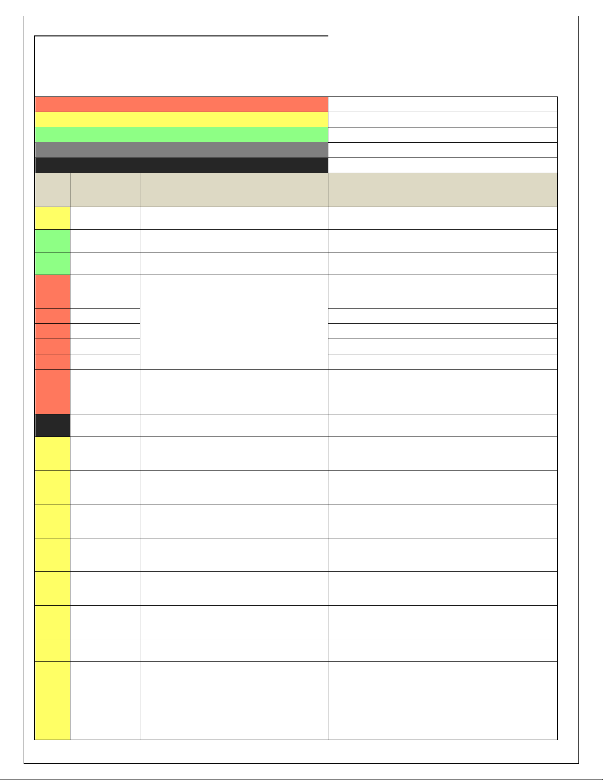
Infinity ECU Pinout
Infinity - 10, P/N 30-7100/01
Dedicated
Dedicated and not reconfigurable
Assigned
Assigned but reconfigurable
Available
Available for user setup
Not Applicable
Not used in this configuration
Required
Required for proper function
Infinity
Pin
Hrdwr Ref.
Hardware Specification
Notes
C1-1
LowsideSwitch_4
Lowside switch, 4A max, NO internal flyback diode.
See Setup Wizard Pages "User GPOs" for activation criteria and
"LowSide Assignment Tables" for output assignment
C1-2
LowsideSwitch_5
Lowside switch, 4A max with internal flyback diode.
Inductive load should NOT have full time power.
See Setup Wizard Page "LowSide Assignment Tables" for output
assignment and 2D table "LS5_Duty [%]" for activation.
C1-3
LowsideSwitch_6
Lowside switch, 4A max with internal flyback diode.
Inductive load should NOT have full time power.
See Setup Wizard Page "LowSide Assignment Tables" for output
assignment and 2D table "LS6_Duty [%]" for activation.
C1-4
UEGO 1 Heat
Bosch UEGO controller
Lowside switch for UEGO heater control. Connect to pin 4 of
Bosch UEGO sensor. NOTE that pin 3 of the Sensor is heater (+)
and must be power by a fused/switched 12V supply.
C1-5
UEGO 1 IA
Trim Current signal. Connect to pin 2 of Bosch UEGO sensor
C1-6
UEGO 1 IP
Pumping Current signal. Connect to pin 6 of Bosch UEGO sensor
C1-7
UEGO 1 UN
Nernst Voltage signal. Connect to pin 1 of Bosch UEGO sensor
C1-8
UEGO 1 VM
Virtual Ground signal. Connect to pin 5 of Bosch UEGO sensor.
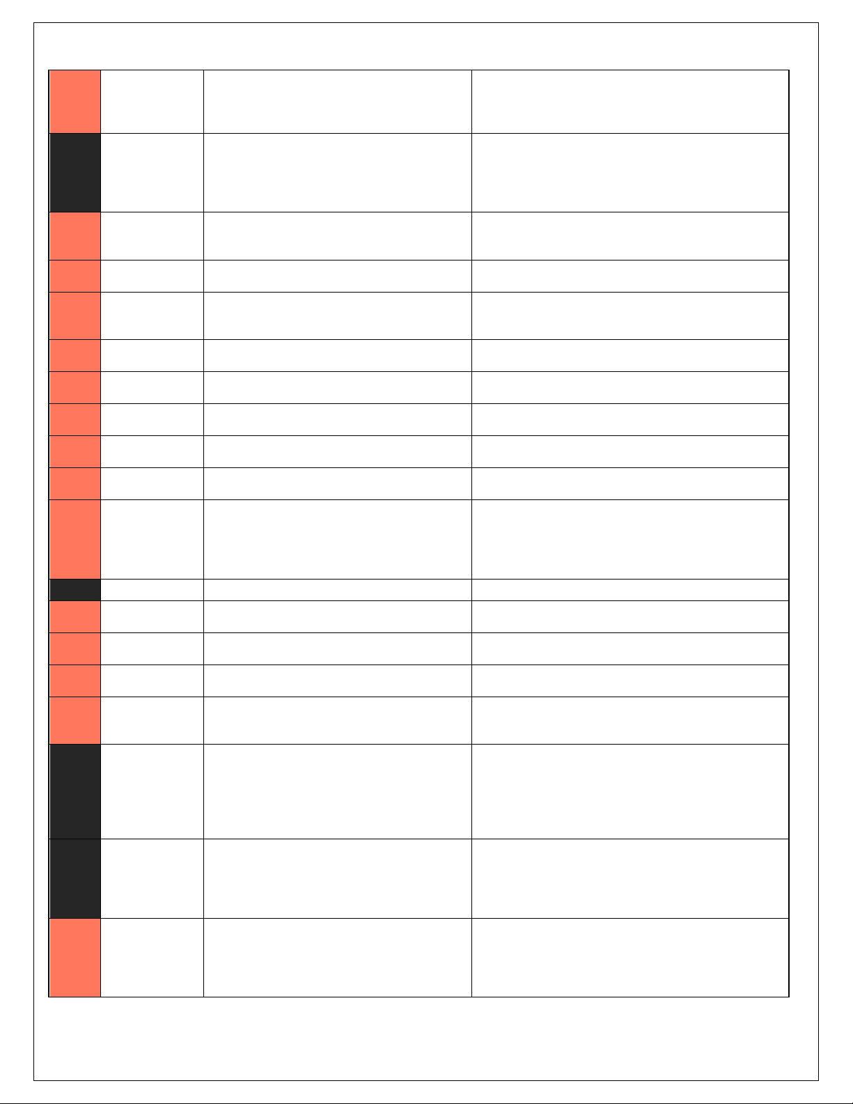
C1-9
Flash_Enable
10K pulldown
Not usually needed for automatic firmware updates through
Infinity Tuner. If connection errors occur during update,
connect 12 volts to this pin before proceeding with upgrade.
Disconnect the 12 volts signal after the update.
C1-10
+12V_R8C_CPU
Dedicated power management CPU
Full time battery power. MUST be powered before the ignition
switch input is triggered (See C1-65).
C1-11
Coil 4
25 mA max source current
0-5V Falling edge fire. DO NOT connect directly to coil primary.
Must use an ignitor OR CDI that accepts a FALLING edge fire
signal.
C1-12
Coil 3
25 mA max source current
0-5V Falling edge fire. DO NOT connect directly to coil primary.
Must use an ignitor OR CDI that accepts a FALLING edge fire
signal.
C1-13
Coil 2
25 mA max source current
0-5V Falling edge fire. DO NOT connect directly to coil primary.
Must use an ignitor OR CDI that accepts a FALLING edge fire
signal.
C1-14
Coil 1
25 mA max source current
0-5V Falling edge fire. DO NOT connect directly to coil primary.
Must use an ignitor OR CDI that accepts a FALLING edge fire
signal.
C1-15
Coil 6
25 mA max source current
0-5V Falling edge fire. DO NOT connect directly to coil primary.
Must use an ignitor OR CDI that accepts a FALLING edge fire
signal.
C1-16
Coil 5
25 mA max source current
0-5V Falling edge fire. DO NOT connect directly to coil primary.
Must use an ignitor OR CDI that accepts a FALLING edge fire
signal.
C1-17
LowsideSwitch_2
Lowside switch, 4A max, NO internal flyback diode.
See Setup Wizard Pages "User GPOs" for activation criteria and
"LowSide Assignment Tables" for output assignment
C1-18
LowsideSwitch_3
Lowside switch, 4A max with internal flyback diode.
Inductive load should NOT have full time power.
See Wizard page "LowSide Assignment Tables" for output
assignment.
MIL Activates when any of the following flags are true:
ErrorAirTemp, ErrorBaro, ErrorCoolantTemp, ErrorEBP,
ErrorFuelPressure, UEGO_0_Diag_error, UEGO_1_Diag_error,
ErrorMAFAnalog, ErrorMAFDigital, ErrorMAP, ErrorOilPressure,
ErrorThrottle.
Rev A, 2013/02/05
Page 17
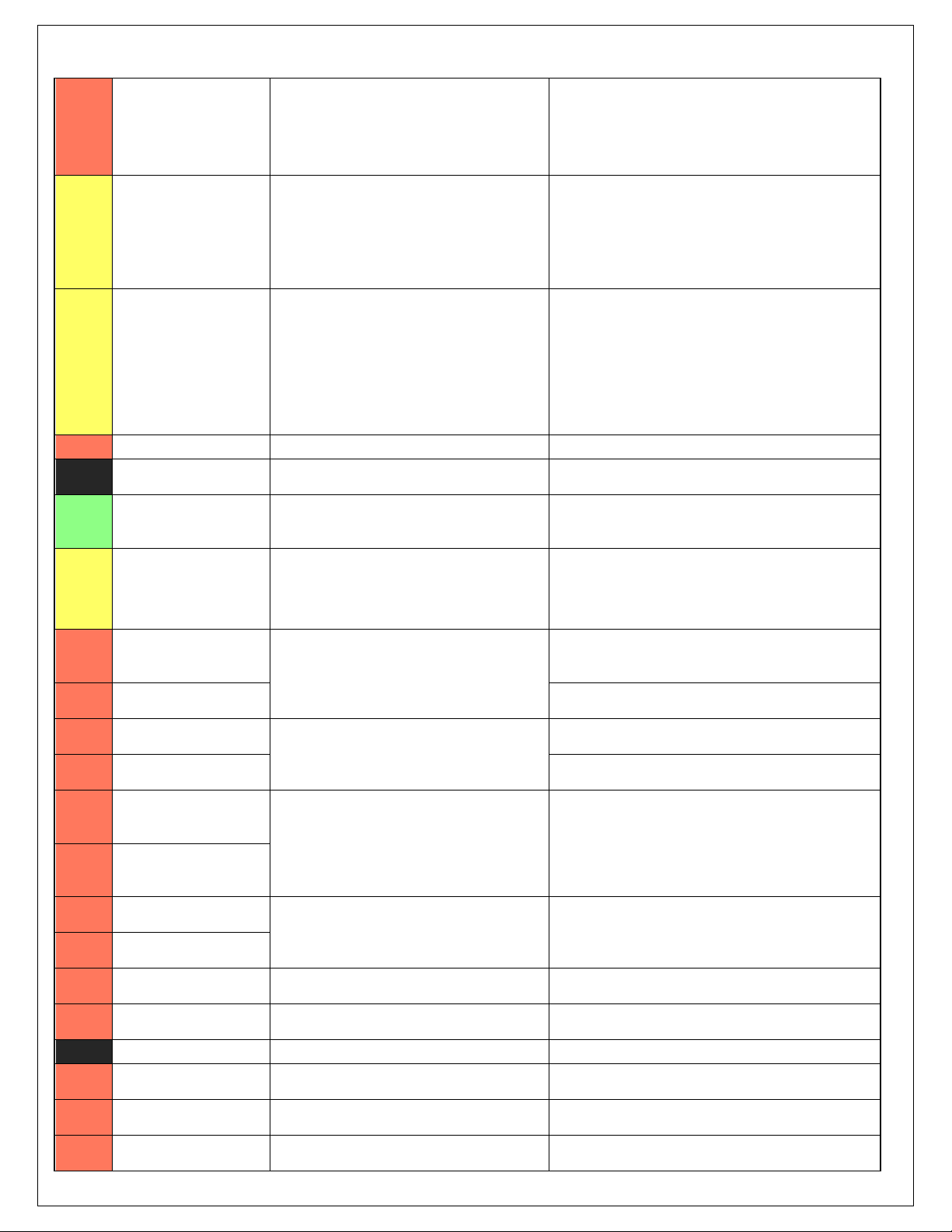
C1-19
AGND_1
Dedicated analog ground
Analog 0-5V sensor ground
C1-20
AGND_1
Dedicated analog ground
Analog 0-5V sensor ground
C1-21
Crankshaft
Position Sensor
Hall
10K pullup to 12V. Will work with ground or
floating switches.
See Setup Wizard page Cam/Crank for options.
C1-22
Camshaft Position
Sensor 1 Hall
10K pullup to 12V. Will work with ground or
floating switches.
See Setup Wizard page Cam/Crank for options.
C1-23
Digital_In_2
10K pullup to 12V. Will work with ground or
floating switches.
See Setup Wizard page Cam/Crank for options.
C1-24
Digital_In_3
10K pullup to 12V. Will work with ground or
floating switches.
See Setup Wizard page Turbo Speed for calibration constant.
TurboSpeed [RPM] = Turbo [Hz] * Turbo Speed Calibration.
C1-25
Digital_In_4
10K pullup to 12V. Will work with ground or
floating switches.
See Setup Wizard page Vehicle Speed for calibration constant.
C1-26
Digital_In_5
10K pullup to 12V. Will work with ground or
floating switches.
See channel FlexDigitalIn [Hz] for raw frequency input data.
C1-27
Knock Sensor 1
Dedicated knock signal processor
See Setup Wizard page Knock Setup for options.
C1-28
Knock Sensor 2
Dedicated knock signal processor
See Setup Wizard page Knock Setup for options.
C1-29
+12V_Relay_Cont
rol
0.7A max ground sink for external relay control
Will activate at key on and at key off according to the
configuration settings.
C1-30
Power Ground
Power Ground
Connect directly to battery ground
C1-31
CANL_Aout
Dedicated High Speed CAN Transceiver
Recommend twisted pair (one twist per 2") with terminating
resistor. Contact AEM for additional information.
C1-32
CANH_Aout
Dedicated High Speed CAN Transceiver
Recommend twisted pair (one twist per 2") with terminating
resistor. Contact AEM for additional information.
C1-33
LowsideSwitch_1
Lowside switch, 4A max with internal flyback diode.
Inductive load should NOT have full time power.
See Setup Wizard page Boost Control for options. Monitor
BoostControl [%] channel for output state.
C1-34
Lowside Fuel
Pump drive
Lowside switch, 4A max, NO internal flyback diode.
Switched ground. Will prime for 2 seconds at key on and
activate if RPM > 0.
C1-35
Analog_In_7
12 bit A/D, 100K pullup to 5V
0-5V analog signal. Use +5V Out pins as power supply and
Sensor Ground pins as the low reference. Do not connect
signals referenced to +12V as this can permanently damage
the ECU. See the Setup Wizard Set Throttle Range page for
automatic min/max calibration. Monitor the Throttle [%]
channel. Also DB1_TPSA [%] for DBW applications.
C1-36
Analog_In_8
12 bit A/D, 100K pullup to 5V
0-5V analog signal. Use +5V Out pins as power supply and
Sensor Ground pins as the low reference. Do not connect
signals referenced to +12V as this can permanently damage
the ECU. See the Setup Wizard Set Manifold Pressure page for
setup and calibration. Monitor the MAP [kPa] channel.
C1-37
Analog_In_9
12 bit A/D, 100K pullup to 5V
0-5V analog signal. Use +5V Out pins as power supply and
Sensor Ground pins as the low reference. Do not connect
signals referenced to +12V as this can permanently damage
the ECU. See the Setup Wizard Fuel Pressure page for setup
and calibration. Monitor the FuelPressure [psig] channel.
Rev A, 2013/02/05
Page 18
C1-38
Analog_In_10
12 bit A/D, 100K pullup to 5V
0-5V analog signal. Use +5V Out pins as power supply and
Sensor Ground pins as the low reference. Do not connect
signals referenced to +12V as this can permanently
damage the ECU. See the Setup Wizard Barometric
Pressure page for setup and calibration. Monitor the
BaroPress [kPa] channel.
C1-39
Analog_In_11
12 bit A/D, 100K pullup to 5V
0-5V analog signal. Use +5V Out pins as power supply and
Sensor Ground pins as the low reference. Do not connect
signals referenced to +12V as this can permanently
damage the ECU.
See the 1D lookup table 'ShiftSwitch' for setup. Also
assignable to multiple functions. See Setup Wizard for
details.
C1-40
Analog_In_12
12 bit A/D, 100K pullup to 5V
0-5V analog signal. Use +5V Out pins as power supply and
Sensor Ground pins as the low reference. Do not connect
signals referenced to +12V as this can permanently
damage the ECU.
See the 1D lookup table 'ModeSwitch' for input state.
A multi-position rotary switch such as AEM P/N 30-2056 is
recommended.
Also assignable to multiple functions. See Setup Wizard
for details.
C1-41
+5V_Out_1
Regulated, fused +5V supply for sensor power
Analog sensor power
C1-42
+5V_Out_1
Regulated, fused +5V supply for sensor power
Analog sensor power
C1-43
HighsideSwitch_1
0.7A max, High Side Solid State Relay
See Setup Wizard page 'HighSide Assigment Tables' for
configuration options. See 2D lookup table 'HS1_Table'
for activation settings.
C1-44
HighsideSwitch_0
0.7A max, High Side Solid State Relay
See Setup Wizard page 'HighSide Assigment Tables' for
configuration options. See 2D lookup table 'HS0_Table'
for activation settings.
See Setup Wizard page 'VTEC' for default activation
criteria.
C1-45
Crankshaft Position
Sensor VR+
Differential Variable Reluctance Zero Cross
Detection
See Setup Wizard page Cam/Crank for options.
C1-46
Crankshaft Position
Sensor VR-
See Setup Wizard page Cam/Crank for options.
C1-47
Camshaft Position Sensor
1 VR-
Differential Variable Reluctance Zero Cross
Detection
See Setup Wizard page Cam/Crank for options.
C1-48
Camshaft Position Sensor
1 VR+
See Setup Wizard page Cam/Crank for options.
C1-49
VR+_In_2
Differential Variable Reluctance Zero Cross
Detection
See Non Driven Wheel Speed Calibration in the Setup
Wizard Vehicle Speed page.
C1-50
VR-_In_2
C1-51
VR-_In_3
Differential Variable Reluctance Zero Cross
Detection
See Driven Wheel Speed Calibration in the Setup Wizard
Vehicle Speed page.
C1-52
VR+_In_3
C1-53
DBW1 Motor -
5.0A max Throttle Control Hbridge Drive
+12V to close
C1-54
DBW1 Motor +
5.0A max Throttle Control Hbridge Drive
+12V to open
C1-55
Power Ground
Power Ground
Connect directly to battery ground
C1-56
Injector 6
Saturated or peak and hold, 3A max continuous
Injector 6
C1-57
Injector 5
Saturated or peak and hold, 3A max continuous
Injector 5
C1-58
Injector 4
Saturated or peak and hold, 3A max continuous
Injector 4
Rev A, 2013/02/05
Page 19
C1-59
Injector 3
Saturated or peak and hold, 3A max continuous
Injector 3
C1-60
Power Ground
Power Ground
Connect directly to battery ground
C1-61
+12V
12 volt power from relay
12 volt power from relay. Relay must be controlled by
+12V Relay Control signal, pin C1-29 above.
C1-62
Injector 2
Saturated or peak and hold, 3A max continuous
Injector 2
C1-63
Injector 1
Saturated or peak and hold, 3A max continuous
Injector 1
C1-64
+12V
12 volt power from relay
12 volt power from relay. Relay must be controlled by
+12V Relay Control signal pin C1-29 above.
C1-65
+12V_SW
10K pulldown
Full time battery power must be available at C1-10 before
this input is triggered.
C1-66
Analog_In_Temp_1
12 bit A/D, 2.49K pullup to 5V
See "Coolant Temperature" Setup Wizard for selection.
C1-67
Analog_In_Temp_2
12 bit A/D, 2.49K pullup to 5V
See "Air Temperature" Setup Wizard for selection.
C1-68
Harness_Analog_In_Temp
_3
12 bit A/D, 2.49K pullup to 5V
See 1D table OilTempCal table for calibration data and
OilTemp [C] for channel data.
C1-69
Stepper_2A
Automotive, Programmable Stepper Driver, up
to 28V and ±1.4A
Be sure that each internal coil of the stepper motor are
properly paired with the 1A/1B and 2A/2B ECU outputs.
Supports Bi-Polar stepper motors only.
C1-70
Stepper_1A
Automotive, Programmable Stepper Driver, up
to 28V and ±1.4A
Be sure that each internal coil of the stepper motor are
properly paired with the 1A/1B and 2A/2B ECU outputs.
Supports Bi-Polar stepper motors only.
C1-71
Stepper_2B
Automotive, Programmable Stepper Driver, up
to 28V and ±1.4A
Be sure that each internal coil of the stepper motor are
properly paired with the 1A/1B and 2A/2B ECU outputs.
Supports Bi-Polar stepper motors only.
C1-72
Stepper_1B
Automotive, Programmable Stepper Driver, up
to 28V and ±1.4A
Be sure that each internal coil of the stepper motor are
properly paired with the 1A/1B and 2A/2B ECU outputs.
Supports Bi-Polar stepper motors only.
C1-73
Power Ground
Power Ground
Connect directly to battery ground
C2-1
DBW2 Motor +
5.0A max Throttle Control Hbridge Drive
+12V to open
C2-2
DBW2 Motor -
5.0A max Throttle Control Hbridge Drive
+12V to close
C2-3
Power Ground
Power Ground
Connect directly to battery ground
C2-4
Injector 7
Saturated or peak and hold, 3A max continuous
Injector 7
C2-5
Injector 8
Saturated or peak and hold, 3A max continuous
Injector 8
C2-6
Injector 9
Saturated or peak and hold, 3A max continuous
Injector 9
C2-7
Injector 10
Saturated or peak and hold, 3A max continuous
Injector 10
C2-8
Power Ground
Power Ground
Connect directly to battery ground
C2-9
+12V
12 volt power from relay
12 volt power from relay. Relay must be controlled by
+12V Relay Control signal, pin C1-29 above.
C2-10
Injector 11
Saturated or peak and hold, 3A max continuous
Not used
C2-11
Injector 12
Saturated or peak and hold, 3A max continuous
Not used
Rev A, 2013/02/05
Page 20
C2-12
Analog_In_17
12 bit A/D, 100K pullup to 5V
0-5V analog signal. Use +5V Out pins as power supply and
Sensor Ground pins as the low reference. Do not connect
signals referenced to +12V as this can permanently damage
the ECU. See Setup Wizard Input Functions page for input
selection. See AC_Request_In 1-axis table for activation logic.
C2-13
Analog_In_18
12 bit A/D, 100K pullup to 5V
0-5V analog signal. Use +5V Out pins as power supply and
Sensor Ground pins as the low reference. Do not connect
signals referenced to +12V as this can permanently damage
the ECU.
C2-14
Analog_In_19
12 bit A/D, 100K pullup to 5V
0-5V analog signal. Use +5V Out pins as power supply and
Sensor Ground pins as the low reference. Do not connect
signals referenced to +12V as this can permanently damage
the ECU.
C2-15
Analog_In_Temp
_4
12 bit A/D, 2.49K pullup to 5V
See ChargeOutTemp [C] table for calibration data and
ChargeOutTemp [C] for channel data.
C2-16
Analog_In_Temp
_5
12 bit A/D, 2.49K pullup to 5V
See AirboxTemp [C] table for calibration data and AirboxTemp
[C] for channel data.
C2-17
Analog_In_Temp
_6
12 bit A/D, 2.49K pullup to 5V
See FuelTemp [C] table for calibration data and FuelTemp [C]
for channel data.
C2-18
Analog_In_13
12 bit A/D, 100K pullup to 5V
0-5V analog signal. Use +5V Out pins as power supply and
Sensor Ground pins as the low reference. Do not connect
signals referenced to +12V as this can permanently damage
the ECU. See Setup Wizard Oil Pressure page for setup
options. See OilPressure [psig] for channel data.
C2-19
Analog_In_14
12 bit A/D, 100K pullup to 5V
0-5V analog signal. Use +5V Out pins as power supply and
Sensor Ground pins as the low reference. Do not connect
signals referenced to +12V as this can permanently damage
the ECU. See the TC_SlipTrgtTrim [MPH] 1-axis table. A multiposition rotary switch such as AEM P/N 30-2056 is
recommended.
C2-20
Analog_In_15
12 bit A/D, 100K pullup to 5V
0-5V analog signal. Use +5V Out pins as power supply and
Sensor Ground pins as the low reference. Do not connect
signals referenced to +12V as this can permanently damage
the ECU. See Setup Wizard Exhaust Pressure page for setup
options. See EBPress [kPa] for channel data.
C2-21
Analog_In_16
12 bit A/D, 100K pullup to 5V
0-5V analog signal. Use +5V Out pins as power supply and
Sensor Ground pins as the low reference. Do not connect
signals referenced to +12V as this can permanently damage
the ECU.
C2-22
+5V_Out_2
Regulated, fused +5V supply for sensor power
Analog sensor power
C2-23
+5V_Out_2
Regulated, fused +5V supply for sensor power
Analog sensor power
C2-24
+5V_Out_2
Regulated, fused +5V supply for sensor power
Analog sensor power
C2-25
VR+_In_5
Differential Variable Reluctance Zero Cross
Detection
See Driven Wheel Speed Calibration in the Setup Wizard
Vehicle Speed page.
C2-26
VR-_In_5
C2-27
VR-_In_4
Differential Variable Reluctance Zero Cross
Detection
See Non Driven Wheel Speed Calibration in the Setup Wizard
Vehicle Speed page.
C2-28
V R+_In_4
C2-29
LowsideSwitch_9
Lowside switch, 4A max with internal flyback diode,
2.2K 12V pullup. Inductive load should NOT have full
time power.
See Setup Wizard page Tacho for configuration options.
C2-30
AGND_2
Dedicated analog ground
Analog 0-5V sensor ground
Rev A, 2013/02/05
Page 21
C2-31
AGND_2
Dedicated analog ground
Analog 0-5V sensor ground
C2-32
AGND_2
Dedicated analog ground
Analog 0-5V sensor ground
C2-33
Analog_In_20
12 bit A/D, 100K pullup to 5V
0-5V analog signal. Use +5V Out pins as power supply and
Sensor Ground pins as the low reference. Do not connect
signals referenced to +12V as this can permanently damage the
ECU.
C2-34
Analog_In_21
12 bit A/D, 100K pullup to 5V
0-5V analog signal. Use +5V Out pins as power supply and
Sensor Ground pins as the low reference. Do not connect
signals referenced to +12V as this can permanently damage the
ECU. See 3StepSwitch 1-axis table for setup.
C2-35
Analog_In_22
12 bit A/D, 100K pullup to 5V
0-5V analog signal. Use +5V Out pins as power supply and
Sensor Ground pins as the low reference. Do not connect
signals referenced to +12V as this can permanently damage the
ECU. See USBLoggingRequestIn channel for input state. See
Setup Wizard page USB Logging for configuration options.
C2-36
Analog_In_23
12 bit A/D, 100K pullup to 5V
0-5V analog signal. Use +5V Out pins as power supply and
Sensor Ground pins as the low reference. Do not connect
signals referenced to +12V as this can permanently damage the
ECU. See ChargeOutPress [kPa] channel for input state. See
Setup Wizard page Charge Out Pressure for calibration options.
C2-37
Digital_In_6
No pullup. Will work with TTL signals.
Input can be assigned to different pins. See Setup Wizard page
Input Function Assignments for input mapping options.
C2-38
Digital_In_7
No pullup. Will work with TTL signals.
See ClutchSwitch 1-axis table for setup options. Input can be
assigned to different pins. See Setup Wizard page Input
Function Assignments for input mapping options.
C2-39
Power Ground
Power Ground
Connect directly to battery ground
C2-40
Power Ground
Power Ground
Connect directly to battery ground
C2-41
CanH_Bout
Dedicated High Speed CAN Transceiver
Not used
C2-42
CanL_Bout
Dedicated High Speed CAN Transceiver
Not used
C2-43
LowsideSwitch
_8
Lowside switch, 4A max with internal flyback diode.
Inductive load should NOT have full time power.
Activates if any of the following flags are true:
OilPressProtectOut, LeanProtectOut, CoolantProtect. Output
can be assigned to other functions. See Setup Wizard page
LowSide Assignment Tables for additional options.
C2-44
LowsideSwitch
_7
Lowside switch, 4A max with internal flyback diode.
Inductive load should NOT have full time power.
See Spare GPO1 Basic Setup section of User GPIOs and PWM
Setup Wizard page LowSide Assignment Tables for additional
options.
C2-45
UEGO 2 VM
Bosch UEGO Controller
Virtual Ground signal. Connect to pin 5 of Bosch UEGO sensor.
C2-46
UEGO 2 UN
Nernst Voltage signal. Connect to pin 1 of Bosch UEGO sensor
C2-47
UEGO 2 IP
Pumping Current signal. Connect to pin 6 of Bosch UEGO sensor
C2-48
UEGO 2 IA
Trim Current signal. Connect to pin 2 of Bosch UEGO sensor
C2-49
UEGO 2 HEAT
Lowside switch for UEGO heater control. Connect to pin 4 of
Bosch UEGO sensor. NOTE that pin 3 of the Sensor is heater (+)
and must be power by a fused/switched 12V supply.
C2-50
+12V_R8C_CP
U
Dedicated power management CPU
Optional full time battery power. MUST be powered before the
ignition switch input is triggered (See C1-65).
C2-51
Coil 7
25 mA max source current
0-5V Falling edge fire. DO NOT connect directly to coil primary.
Must use an ignitor OR CDI that accepts a FALLING edge fire
signal.
Rev A, 2013/02/05
Page 22
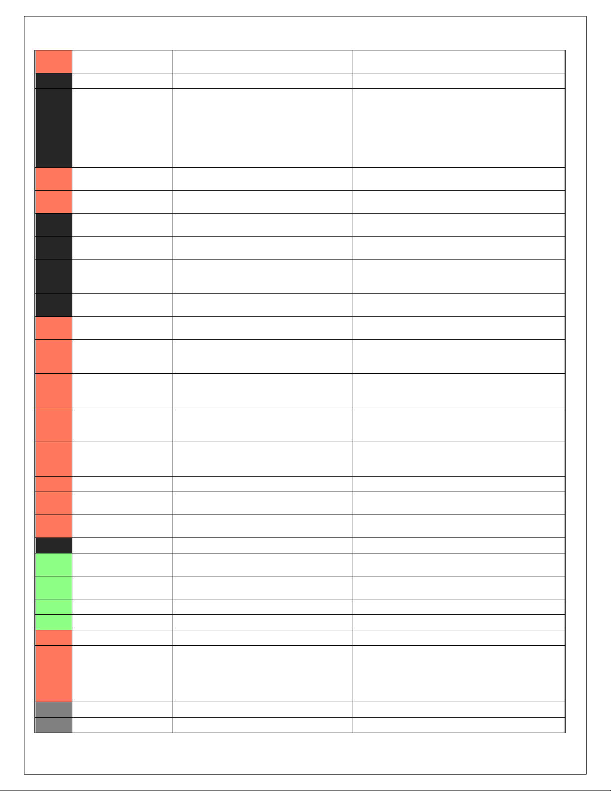
C2-52
Coil 8
25 mA max source current
0-5V Falling edge fire. DO NOT connect directly to coil primary.
Must use an ignitor OR CDI that accepts a FALLING edge fire
signal.
C2-53
Coil 9
25 mA max source current
0-5V Falling edge fire. DO NOT connect directly to coil primary.
Must use an ignitor OR CDI that accepts a FALLING edge fire
signal.
C2-54
Coil 10
25 mA max source current
0-5V Falling edge fire. DO NOT connect directly to coil primary.
Must use an ignitor OR CDI that accepts a FALLING edge fire
signal.
C2-55
Highside Fuel
Pump switch
Highside switch, 0.7A max, Solid State Relay, NO
internal flyback diode.
+12V High Side Drive. Will prime for 2 seconds at key on and
activate if RPM > 0.
C2-56
Not used
Not used
Not used
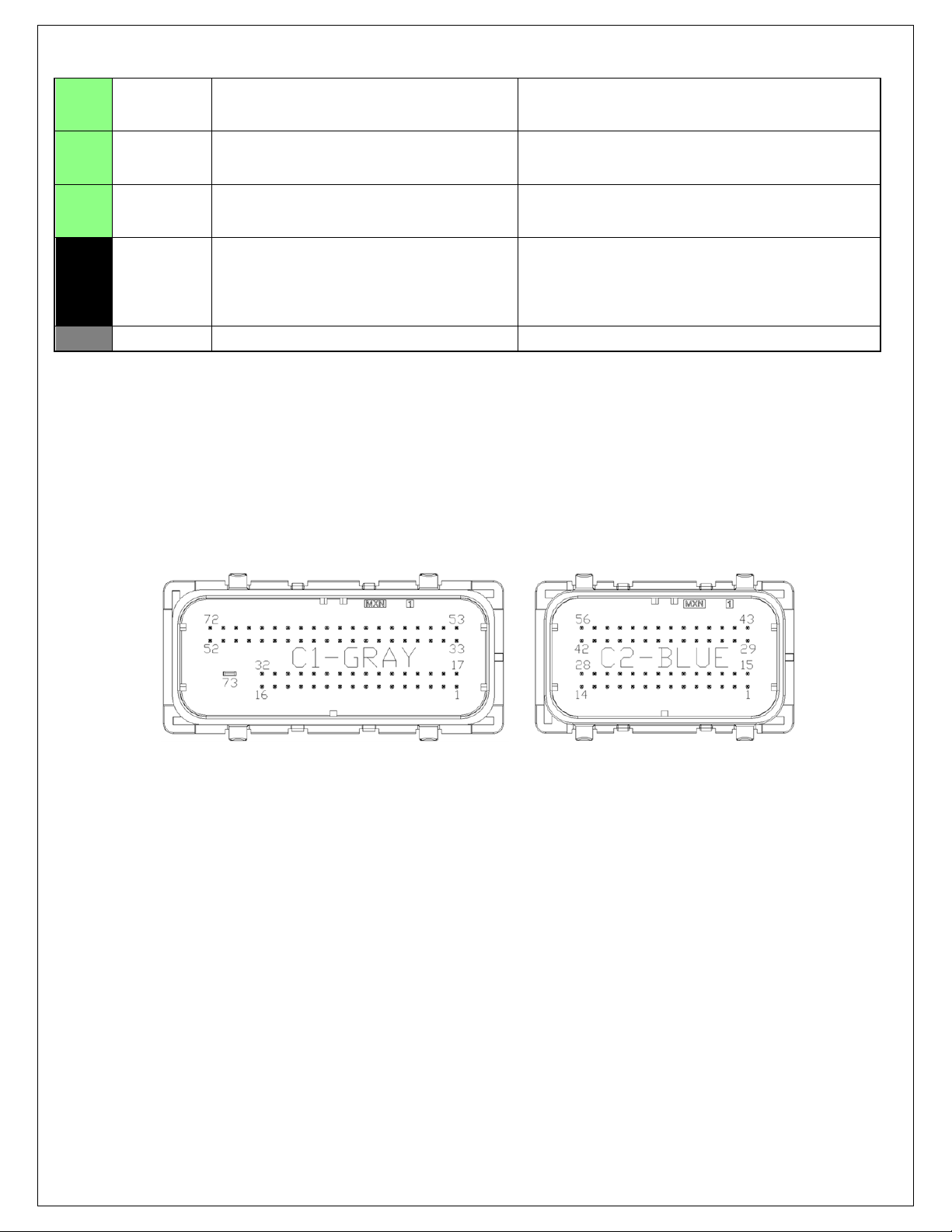
AEM Infinity Connectors Viewed From Wire Side
Rev A, 2013/02/05
Page 23

12 Month Limited Warranty
Advanced Engine Management, Inc. warrants to the consumer that all AEM High Performance products will be free from defects in
material and workmanship for a period of twelve (12) months from date of the original purchase. Products that fail within this 12 month
warranty period will be repaired or replaced at AEM’s option, when determined by AEM that the product failed due to defects in material
or workmanship.
This warranty is limited to the repair or replacement of the AEM part. In no event shall this warranty exceed the original purchase price
of the AEM part nor shall AEM be responsible for special, incidental or consequential damages or cost incurred due to the failure of this
product.
Warranty claims to AEM must be transportation prepaid and accompanied with dated proof of purchase. This warranty applies
only to the original purchaser of product and is non-transferable. All implied warranties shall be limited in duration to the said 12 month
warranty period. Improper use or installation, accident, abuse, unauthorized repairs or alterations voids this warranty.
An AEM Warranty Claim Form Must Accompany All Warranty Claims. Products returned to AEM with no Return Goods
Authorization and or No Warranty Claim Form may be rejected and returned to sender.
AEM disclaims any liability for consequential damages due to breach of any written or implied warranty on all products manufactured by
AEM. Warranty returns will only be accepted be AEM when accompanied by a valid Return Goods Authorization (RGA) number. Credit
for defective products will be issued pending inspection. Product must be received by AEM within 30 days of the date RGA was issued.
Please note that before we can issue an RGA for any product, it is first necessary for the installer or end user to contact our
EMS tech line at (800) 423-0046 to discuss the problem. Most issues can be solved over the phone. Under no circumstances
should a product be returned or RGA requested before the above process transpires.
AN AEM WARRANTY CLAIM FORM MUST ACCOMPANY ALL ELECTRONICS WARRANTY CLAIMS. AEM ELECTRONIC
Products returned to AEM with no RGA and or No Warranty Claim Form may be rejected and returned to sender.
A copy of the AEM Warranty Claim Form can be e-mailed or faxed by contacting (310) 484-2322 and ask for Warranty/Claims
Department.
Need additional help? Contact the AEM Performance Electronics tech department at 1-800-423-0046 or tech@aempower.com,
or visit the AEM Performance Electronics forum at: http://forum.aempower.com/forum/
Rev A, 2013/02/05
 Loading...