

Page 1
Instruction
STOP!
THIS PRODUCT HAS LEGAL RESTRICTIONS.
READ THIS BEFORE INSTALLING/USING!
THIS PRODUCT MAY BE USED SOLELY ON VEHICLES USED IN SANCTIONED COMPETITION WHICH MAY
NEVER BE USED UPON A PUBLIC ROAD OR HIGHWAY, UNLESS PERMITTED BY SPECIFIC REGULATORY
EXEMPTION. (VISIT THE “EMISSIONS” PAGE AT HTTP://WWW.SEMASAN.COM/EMISSIONS FOR STATE BY
STATE DETAILS.)
IT IS THE RESPONSIBILITY OF THE INSTALLER AND/OR USER OF THIS PRODUCT TO ENSURE THAT IT IS
USED IN COMPLIANCE WITH ALL APPLICABLE LAWS AND REGULATIONS. IF YOU HAVE PURCHASED
THIS PRODUCT IN ERROR, DO NOT INSTALL AND/OR USE IT. PLEASE CONTACT THE RETAILER FROM
WHOM YOU PURCHASED THE PRODUCT TO ARRANGE A RETURN FOR A FULL REFUND OR VISIT
AEMELECTRONICS.COM/PRODUCT-LEGAL-RESTRICTIONS FOR FURTHER INSTRUCTIONS.
Manual
P/N 30-3508
2000–2005 Honda S2000
Infinity-6 and Infinity-8h*
Plug & Play Adapter Harness
WARNING: This installation is not for the tuning novice! Use this system with EXTREME caution! The AEM
Infinity Programmable EMS allows for total flexibility in engine tuning. Misuse or improper tuning of this
product can destroy your engine! If you are not well versed in engine dynamics and the tuning of engine
management systems DO NOT attempt the installation. Refer the installation to an AEM-trained tuning
shop or call 800-423-0046 for technical assistance.
NOTE: All supplied AEM calibrations, Wizards and other tuning information are offered as potential
starting points only. IT IS THE RESPONSIBILITY OF THE ENGINE TUNER TO ULTIMATELY CONFIRM IF THE
CALIBRATION IS SAFE FOR ITS INTENDED USE. AEM holds no responsibility for any engine damage that
results from the misuse or mistuning of this product!
*See next page for important information regarding the use of this harness with Infinity-8h
AEM Performance Electronics, 2205 126th Street Unit A, Hawthorne, CA 90250
AEM Performance Electronics
Phone: (310) 484-2322 Fax: (310) 484-0152
http://www.aemelectronics.com
Instruction Part Number: 10-3508
Document Build 8/25/2014
Page 2
2
P/N 30-3508
OVERVIEW
The 30-3508 AEM Infinity Adapter Kit is designed for the 2000–2005 Honda S2000. These models include
all 2.0L (AP1) engines as well as the early 2.2L (AP2) engines with a cable driven throttle body. This is a
true standalone system that eliminates the use of the factory ECU. The use of this adapter makes the kit
“plug and play” so no cutting or splicing wires is necessary. The base configuration files available for the
Infinity EMS are starting points only and will need to be modified for every specific application.
The available AEM Infinity EMS part numbers for this adapter kit are:
30-7106 INFINITY-6
30-7108 INFINITY-8h
GETTING STARTED
Refer to the 10-7100 for EMS 30-7100 Infinity Quick Start Guide for additional information on getting
the engine started with the Infinity EMS. Base sessions are located in C:\Documents\AEM\Infinity Tuner
\Sessions\Base Sessions
DOWNLOADABLE FILES
Files can be downloaded from www.aeminfinity.com. An experienced tuner must be available to configure
and manipulate the data before driving can commence. The Quick Start Guide and Full Manual describe
the steps for logging in and registering at www.aeminfinity.com. These documents are available for
download in the Support section of the AEM Electronics website: http://www.aemelectronics.com/
products/support/instructions
Downloadable files for 2000–2005 Honda S2000
OPTIONS
30-2001 UEGO Wideband O2 Sensor
Bosch LSU4.2 Wideband O2 Sensor that connects to AEM 30-3600 UEGO Wideband O2 Sensor
Extension Harness
30-3600 UEGO Wideband O2 Sensor Extension Harness
Extension harness to connect AEM UEGO Wideband O2 sensor to 6-pin Deutsch
30-3602 IP67 Logging Cable
USB A-to-A extension cable: 39” long with right angled connector and bayonet style lock
7106-XXXX-75 Infinity-6 (XXXX = serial number)
7108-XXXX-76 Infinity-8h (XXXX = serial number)
© 2014 AEM Performance Electronics
Page 3

*IMPORTANT INFINITY-8H INFORMATION
Infinity
Pin
Infinity-6
Function
Infinity-8h
Function
30-3508
PnP Honda
Pin
Notes
C1-3
Lowside6
Injector7
A1
OEM Coolant Gauge on Infinity-6 or Injector7 on
Infinity-8h
C1-4
Lowside7
Injector8
A18
MIL on Infinity-6 or Injector8 on Infinity-8h
C1-31
Digital6
Coil7
Aux 6
Available Digital6 on Infinity-6; Coil7 not used on
Infinity-8h. ** Must de-pin for use with Infinity-8h;
Coil7 not used**
C1-32
Digital7
Coil8
A32
Brake Switch input on Infinity-6; Coil8 not used on
Infinity-8h. ** Must de-pin for use with Infinity-8h;
Coil8 not used**
The primary difference between the 30-7106 Infinity-6 and 30-7108 Infinity-8h is that the 8h lacks Peak
& Hold injector drivers to run low impedance fuel injectors. High impedance (saturated, high-z) fuel
injectors must be used with the Infinity-8h.
The Infinity-6 and Infinity-8h share a common pinout with the exception of four pins where the Infinity-8h
has two each additional fuel injector and ignition coil drivers. Due to the additional fuel injector and
ignition coil drivers, the 8h has two fewer digital inputs and lowside outputs. Use of this harness with an
Infinity-8h will require slight modification and will result in loss of some plug and play function- OEM
Coolant Gauge, Malfunction Indicator Light, and Brake Switch input.
2000–2005 Honda S2000
3
INFINITY CONNECTORS
The AEM Infinity EMS uses the MX123 Sealed Connection System
from Molex. Refer to the 10-7100 for EMS 30-7100 Infinity Quick
Start Guide for details on connector assembly and handling.
AEM strongly recommends that users become familiar with the
proper tools and procedures for working with these high density
connectors before attempting any modifications. The entire Molex
MX123 User Manual can be downloaded direct from Molex at:
http://www.molex.com/mx_upload/family//MX123UserManual.pdf
© 2014 AEM Performance Electronics
Page 4
4
P/N 30-3508
INFINITY ADAPTER HARNESS
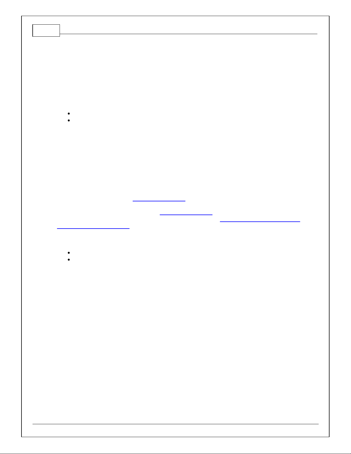
Included with the 2000–2005 Honda S2000 kit is an adapter harness. This is used to make the
connection between the AEM Infinity EMS and the Honda wiring harness plug and play. This is depicted
below with the 80-pin connector and the Honda header. There are also a few other integrated connectors
within this harness described below.
The gray Deutsch 6P DTM “Lambda #1” connector is for connecting a UEGO wideband Bosch LSU4.2
sensor (AEM 30-2001). The UEGO extension harness (AEM 30-3600) mates the adapter harness to the
sensor.
The gray Deutsch 4P DTM connector is used for “AEMNet”. AEMNet is an open architecture based on
CAN 2.0 which provides the ability for multiple enabled devices, such as dashboards, data loggers, etc.,
to easily communicate with one another through two twisted cables (CAN+/CAN-).
The black Delphi 2-pin “Flash Enable” connector is used for secondary hardware flashing. The included
shunt connector jumps the 2 wires together. Once initially flashed, the EMS is normally upgraded in the
software, not using this connector.
The gray Deutsch 12P DTM “Auxiliary” connector
(shown below) is used to adapt many common
ancillary inputs and outputs easily. Included in the kit
are a DTM 12P mating connector, 12 DTM terminals,
and a DTM 12P wedgelock. If used, these
components will need to be terminated by the installer
or end user with 16–22awg wire (not included). Note:
The pin numbering is molded into the connector, as
shown.
© 2014 AEM Performance Electronics
Page 5
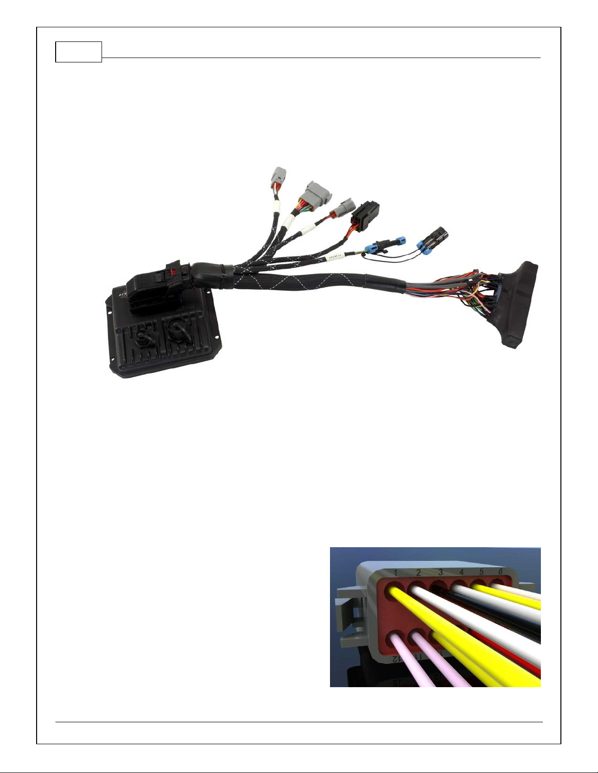
DASHBOARD
The AEM Infinity EMS for the 2000–2005 Honda S2000 drives the Tachometer, Coolant Temperature
Gauge, and the CEL (Check Engine Light). Shown below are the AP1 and AP2 gauge clusters.
Rather than OBD2 diagnostics, the CEL light is now dedicated to the AEM “MILOutput” feature. The
AEM MILOutput activates if any 1 of the following inputs are in an error state: air temp, baro pressure,
coolant temp, exhaust back pressure, fuel pressure, UEGO #1, UEGO #2, MAF analog, MAF digital,
MAP, oil pressure, or throttle position. If any of these sensors are not used, they should be turned OFF
in the Wizard to avoid any false readings. To activate the MILOutput feature, go to the Wizard and check
“Enable MIL Output” in Diagnostics.
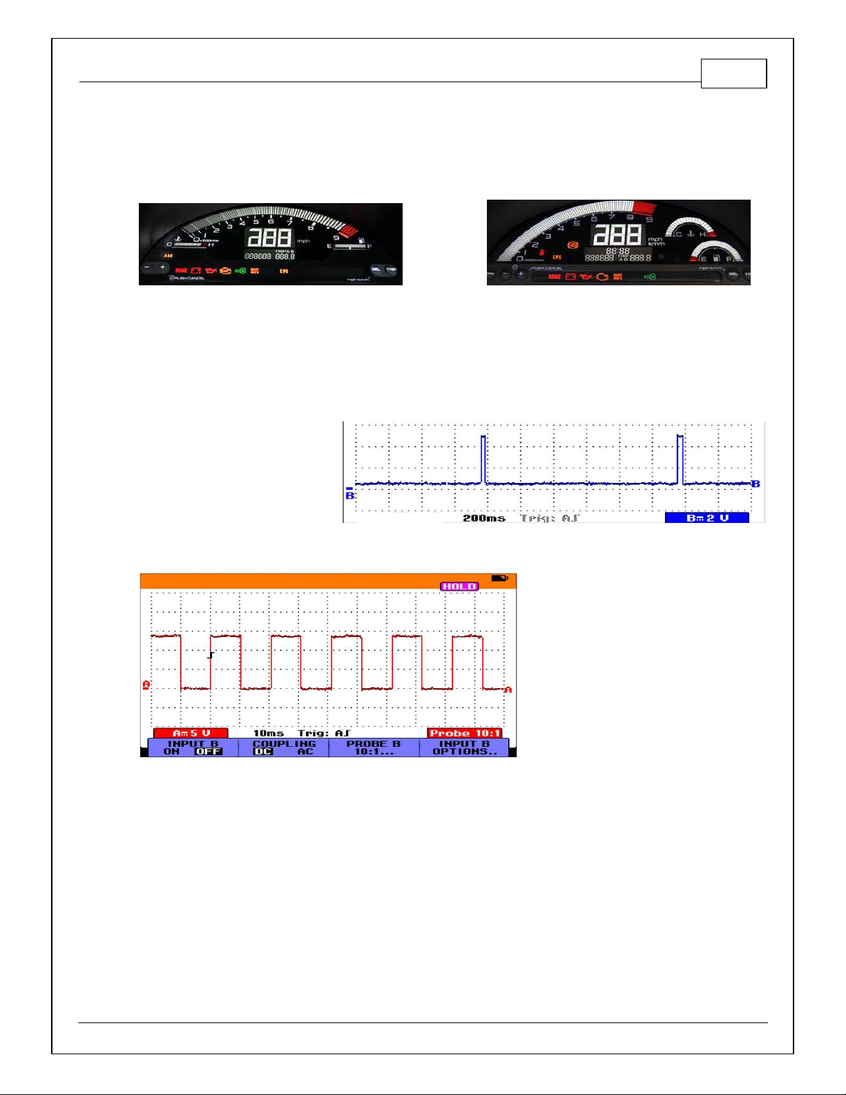
The coolant temp gauge is ECU
driven by a 5V 30ms pulse with a
period that varies with ECT
voltage, as shown. It is precalibrated using a combination of
the LS6_Freq [Hz] 1-axis table
and the LS6_Duty [%] 2-axis
table.
2000–2005 Honda S2000
5
Similarly, the Honda S2000 gauge
cluster’s tachometer is also driven by
the ECU, as shown. However, compared
to the coolant temperature gauge, this
signal is very elementary as it simply
varies frequency with engine speed.
The Honda S2000 tachometer is precalibrated using a combination of the
LS5_Freq [Hz] 1-axis table and the
LS5_Duty [%] 2-axis table.
© 2014 AEM Performance Electronics
Page 6

6
First, make sure the Honda CD Player
activation code is recorded and also take
note of the radio presets. Next, open the
hood and disconnect the battery. Remember
to set the clock when reconnecting the
battery.
The stock ECU is located on the left-side
kick panel, as shown. Pop off and remove the
door sill (not pictured) and kick panel cover,
as shown.
Carefully unplug the 3 ECU connectors by
depressing the “thumb” lock on each
connector. Avoid excessive stress or pulling
on the wires, as this may damage the
harness.
To remove the ECU, unscrew the two
mounting M6 bolts from the mounting
bosses (circled in blue) using a 10mm
socket wrench. These mounting bosses
will not be reused.
As depicted in the picture, the sheet
metal surface in the ECU location is not
entirely flat. However, the included
adhesive hook and loop (Velcro) will still
be used to hold the Infinity EMS in place
while 1 of the OEM ECU bolts will be
reused to secure it to the spare M6
mounting boss, circled in red.
P/N 30-3508
INFINITY EMS INSTALLATION
Step 1
Step 2
© 2014 AEM Performance Electronics
Page 7

Step 3
Attach one side of the Velcro to the
back of the EMS and the other to the
chassis, as shown. Loosely screw the
OEM ECU bolt into the spare boss,
shown in red.
Attach the AEM 80-pin connector to the
EMS. Secure the Infinity connector by
sliding the red locking tab.
Slide the EMS all the way up until the
adapter harness contours around the top
side of the kick panel area. The OEM
ECU bolt should just be present on the
bottom side of the EMS.
Position the EMS onto the hook and
loop strip adhered to the chassis.
Move the EMS so half of the OEM ECU
bolt’s washer locks onto the EMS
mounting tab’s outer edge, as shown.
Tighten this bolt.
Next, connect the three OEM Honda
ECU connectors to the Honda header
found in the AEM adapter. Connect the
included mini USB communication cable
to the EMS.
If there are to be any AEMnet devices
that will be daisy-chained to the Infinity
EMS, secure it to the AEM adapter’s 4P
Deutsch connector.
2000–2005 Honda S2000
7
Step 4
© 2014 AEM Performance Electronics
Page 8

8
If a wideband UEGO sensor was
purchased, put the car on a vehicle lift
(or jack stands).
Weld in a bung or use an existing O2
sensor bung that is pre catalytic
converter for optimal accuracy.
Use a 7/8” wrench to install the
wideband UEGO sensor (OEM location
shown).
The UEGO extension harness (sold
separately) should be routed away from
moving parts and should not come in
contact with excessively hot objects.
To get the UEGO extension harness into
the cockpit, use the factory grommet on
the left side firewall. RHD vehicles will
differ.
Pull grommet from firewall. Cut a small
slit in grommet and push Deutsch
connector through. Reattach grommet to
firewall. Mate extension harness to the
Deutsch connector found in the AEM
adapter.
If any of the auxiliary connections are to
be installed now is the time to assemble
these.
Reconnect the battery, and connect to
the Infinity Tuner software. After all of the
components are verified, reinstall the
kick panel and door sill.
Step 5
Step 6
P/N 30-3508
© 2014 AEM Performance Electronics
Page 9

PINOUTS
Dedicated
Dedicated and not reconfigurable
Assigned
Assigned but reconfigurable
Available
Available for user setup
Not Applicable
Not used in this configuration
Required
Required for proper function
Infinity
Pin
Infinity
Assignment
Honda Pin
Honda Description
Infinity Hardware
Specification
Notes
1
LS 4
A17
A/C Clutch Relay
Lowside switch, 4A max, No
internal flyback diode.
See Setup Wizard Page "LowSide Assignment
Tables" for output assignment and 2D table
"LS4_Duty [%]" f or on/of f activ ation.
2
LS 5
A19
Engine Speed Pulse
Lowside switch, 4A max
with internal fly back diode.
Inductive load should NOT
have f ull time power.
The tachometer is pre-calibrated using a
combination of the LS5_Freq [Hz] 1-axis table
and the LS5_Duty [%] 2-axis table.
3
LS 6
A1
Engine Coolant Temp
Gauge
Lowside switch, 4A max
with internal fly back diode.
Inductive load should NOT
have f ull time power.
The coolant temp gauge is pre-calibrated using
the LS6_Freq [Hz] 1-axis table and the
LS6_Duty [%] 2-axis table. This signal is
pulled up to 5V.
4
LS 7
A18
Malfunction Indicator
Light
Lowside switch, 4A max, No
internal flyback diode.
See Wizard page "LowSide Assignment
Tables" for output assignment and 2D table
"LS3_Duty [%]" f or activation. MIL Activ ates
when any of the following f lags are true:
ErrorAirTemp, ErrorBaro, ErrorCoolantTemp,
ErrorEBP, ErrorFuelPressure,
UEGO_0_Diag_error, UEGO_1_Diag_error,
ErrorMAFAnalog, ErrorMAFDigital, ErrorMAP,
ErrorOilPressure, ErrorThrottle.
5
UEGO1 Heat
---
---
Bosch UEGO controller
Lowside switch f or UEGO heater control.
Connect to pin 4 of Bosch UEGO sensor.
NOTE that pin 3 of the Sensor is heater (+)
and must be power by a f used/switched 12V
supply .
6
UEGO1 IA
---
---
Bosch UEGO controller
Trim Current signal. Connect to pin 2 of
Bosch UEGO sensor
7
UEGO1 IP
---
---
Bosch UEGO controller
Pumping Current signal. Connect to pin 6 of
Bosch UEGO sensor
8
UEGO1 UN
---
---
Bosch UEGO controller
Nernst Voltage signal. Connect to pin 1 of
Bosch UEGO sensor
9
UEGO1 VM
---
---
Bosch UEGO controller
Virtual Ground signal. Connect to pin 5 of
Bosch UEGO sensor.
10
+12V Perm
Power
B21
Voltage Back Up
Dedicated power
management CPU
Full time battery power. MUST be powered
before the ignition switch input is triggered.
11
Coil 4
C14
Ignition Coil Pulse
No. 4
25 mA max source current
0–5V f alling edge f ire. Do NOT connect
directly to coil primary . Must use an ignitor or
CDI that accepts a f alling edge f ire signal.
Infinity Pinout
2000–2005 Honda S2000
9
© 2014 AEM Performance Electronics
Page 10

10
Infinity
Pin
Infinity
Assignment
Honda Pin
Honda Description
Infinity Hardware
Specification
Notes
12
Coil 3
C13
Ignition Coil Pulse
No. 3
25 mA max source current
0–5V f alling edge f ire. Do NOT connect
directly to coil primary . Must use an ignitor or
CDI that accepts a f alling edge f ire signal.
13
Coil 2
C12
Ignition Coil Pulse
No. 2
25 mA max source current
0–5V f alling edge f ire. Do NOT connect
directly to coil primary . Must use an ignitor or
CDI that accepts a f alling edge f ire signal.
14
Coil 1
C4
Ignition Coil Pulse
No. 1
25 mA max source current
0–5V f alling edge f ire. Do NOT connect
directly to coil primary . Must use an ignitor or
CDI that accepts a f alling edge f ire signal.
15
---
---
---
---
---16---
---
---
---
---
17
VR0 (+) -
Crank
C9
CKP -
Dif f erential Variable
Reluctance Zero Cross
Detection
See Setup Wizard page Cam/Crank f or
options.
18
VR0 (-) -
Crank
C8
CKP +
Dif f erential Variable
Reluctance Zero Cross
Detection
See Setup Wizard page Cam/Crank f or
options.
19
VR1 (-) -
Cam
C20
TDC1 +
Dif f erential Variable
Reluctance Zero Cross
Detection
See Setup Wizard page Cam/Crank f or
options.
20
VR1 (+) -
Cam
C21
TDC1 -
Dif f erential Variable
Reluctance Zero Cross
Detection
See Setup Wizard page Cam/Crank f or
options.
21
LS 2
A20
Radiator Fan Control
Lowside switch, 4A max, No
internal flyback diode.
See Setup Wizard Page "LowSide Assignment
Tables" for output assignment and 2D table
"LS2_Duty [%]" f or on/of f activ ation.
22
LS 3
B23
Idle Air Control Valv e
Lowside switch, 4A max
with internal fly back diode.
Inductive load should NOT
have f ull time power.
See Setup Wizard page and corresponding
Tables f or Idle Air Control.
23
Sensor GND
C7
Sensor Ground 1
Dedicated analog ground
Analog 0–5V sensor ground
24
Sensor GND
C18
Sensor Ground 2
Dedicated analog ground
Analog 0–5V sensor ground also found on aux
connector
25
Digital 0 -
Crank
---
---
10K pullup to 12V. Will work
with ground or floating
switches.
The S2000 uses a VR crank sensor.
26
Digital 1 -
Cam1
---
---
10K pullup to 12V. Will work
with ground or floating
switches.
The S2000 uses VR cam sensors.
27
Digital 2 -
Cam2
---
---
10K pullup to 12V. Will work
with ground or floating
switches.
The S2000 uses VR cam sensors.
28
Digital 3 –
Flex Fuel
---
---
10K pullup to 12V. Will work
with ground or floating
switches.
Found on the Aux Connector. Input can be
assigned to different pins. See Setup Wizard
page Input Function Assignments for input
mapping options.
29
Digital 4 -
VSS#1
A9
Vehicle Speed Sensor
10K pullup to 12V. Will work
with ground or floating
switches.
See Setup Wizard page Vehicle Speed for
calibration constant.
30
Digital 5 -
A27
A/C Switch Signal
10K pullup to 12V. Will work
with ground or floating
switches.
See Setup Wizard page for A/C activation
P/N 30-3508
© 2014 AEM Performance Electronics
Page 11

2000–2005 Honda S2000
Infinity
Pin
Infinity
Assignment
Honda Pin
Honda Description
Infinity Hardware
Specification
Notes
31
Digital 6 -
---
---
10K pullup to 12V. Will work
with ground or floating
switches.
Found on the Aux Connector. Input can be
assigned to different pins. See Setup Wizard
page Input Function Assignments for input
mapping options.
32
Digital 7 -
A32
Brake Switch Signal
10K pullup to 12V. Will work
with ground or floating
switches.
Input can be assigned to dif ferent pins. See
Setup Wizard page Input Function
Assignments f or input mapping options.
33
GNDB2Power Ground 1
Power Ground
Connects to chassis ground and AEMNet
34
CAN A -
---
---
Dedicated High Speed CAN
Transceiv er
4P DTM Connector found in AEM adapter
harness. Contact AEM f or additional
information.
35
CAN A +
---
---
Dedicated High Speed CAN
Transceiv er
4P DTM Connector found in AEM adapter
harness. Contact AEM f or additional
information.
36
CAN B -
---
---
Dedicated High Speed CAN
Transceiv er
Not used
37
CAN B +
---
---
Dedicated High Speed CAN
Transceiv er
Not used
38
Temp 1 -
Coolant
Temp
C26
Engine Coolant Temp
Sensor
12 bit A/D, 2.49K pullup to
5V
See "Coolant Temperature" Setup Wizard f or
selection.
39
Temp 2 - Air
Temp
(Manifold)
C25
Intake Air Temp
Sensor
12 bit A/D, 2.49K pullup to
5V
See "Air Temperature" Setup Wizard f or
selection.
40
Temp 3 - Oil
Temp
---
---
12 bit A/D, 2.49K pullup to
5V
Found on the Aux Connector. 0–5V analog
signal
41
LS 0
A15
Fuel Pump Relay
Lowside switch, 4A max, No
internal flyback diode.
Switched ground. Will prime for 2 seconds at
key on and activ ate if RPM > 0.
42
LS 1
---
---
Lowside switch, 4A max
with internal fly back diode.
Inductive load should NOT
have f ull time power.
Found in Aux Connector. See Setup Wizard
page Boost Control for options. Monitor
BoostControl [%] channel for output state.
43
GND
B10
Power Ground 2
Power Ground
Connect directly to battery ground.
44
Knock 0
C22
Knock Sensor
Dedicated knock signal
processor
See Knock in Setup Wizard for options.
45
Knock 1
Dedicated knock signal
processor
See Knock in Setup Wizard for options.
46
GND
B20
Logic Ground 1
Power Ground
Connect directly to battery ground.
47
12V_Relay _
Control
---
---
0.7A max ground sink f or
external relay control
Connects to relay f ound in AEM adapter. Will
activate at key ON and at key OFF according
to the configuration settings.
48
+12V SW
(Ign Switch)
B1
Power Source 1
10K pulldown
Full time battery power must be av ailable at
infinity pin 10 before this input is triggered.
49
+5V_Out
C19
Sensor Voltage 1
Regulated, f used +5V
supply for sensor power
Analog sensor power
50
+5V_Out
C28
Sensor Voltage 2
Regulated, f used +5V
supply for sensor power
Analog sensor power and found on auxiliary
connector
51
Ana7 -
Throttle
C27
Throttle Position
Sensor
12 bit A/D, 100K pullup to
5V
0–5V analog signal. Do not connect signals
referenced to +12V as this can permanently
damage the ECU. See the Setup Wizard Set
Throttle Range page for automatic min/max
calibration.
11
© 2014 AEM Performance Electronics
Page 12

12
Infinity
Pin
Infinity
Assignment
Honda Pin
Honda Description
Infinity Hardware
Specification
Notes
52
Ana8 - Map
C17
MAP Sensor
12 bit A/D, 100K pullup to
5V
0–5V analog signal. See the Manifold
Pressure in Setup Wizard for setup and
calibration.
53
Ana9 - Fuel
Press
---
---
12 bit A/D, 100K pullup to
5V
0–5V analog signal f ound on the Auxiliary
Connector
54
VR2 (+) -
Driv en
Wheel
---
---
Dif f erential Variable
Reluctance Zero Cross
Detection
See Driven Wheel Speed Calibration in the
Setup Wizard Vehicle Speed page.
55
VR2 (-) -
Driv en
Wheel
---
---
Dif f erential Variable
Reluctance Zero Cross
Detection
See Driven Wheel Speed Calibration in the
Setup Wizard Vehicle Speed page.
56
VR3 (-) - Tag
Wheel
---
---
Dif f erential Variable
Reluctance Zero Cross
Detection
See Non Driv en Wheel Speed Calibration in
the Setup Wizard Vehicle Speed page.
57
VR3 (+) - Tag
Wheel
---
---
Dif f erential Variable
Reluctance Zero Cross
Detection
See Non Driv en Wheel Speed Calibration in
the Setup Wizard Vehicle Speed page.
58
HS Out 0
B12
VTEC solenoid Valve
0.7A max, High Side Solid
State Relay
+12V High Side Drive. See Setup Wizard
Honda VTEC page f or options.
59
Stepper_1B
---
---
Automotive, Programmable
Stepper Driver, up to 28V
and ±1.4A
Be sure that each internal coil of the stepper
motor is properly paired with the 1A/1B and
2A/2B ECU outputs. Supports Bi-Polar stepper
motors only .
60
Stepper_2B
---
---
Automotive, Programmable
Stepper Driver, up to 28V
and ±1.4A
Be sure that each internal coil of the stepper
motor is properly paired with the 1A/1B and
2A/2B ECU outputs. Supports Bi-Polar stepper
motors only .
61
HBridge0_0
---
---
5.0A max Throttle Control
Hbridge Drive
2000–2005 S2000 do not use drive by wire
throttle.
62
HBridge0_1
---
---
5.0A max Throttle Control
Hbridge Drive
2000–2005 S2000 do not use drive by wire
throttle.
63
+12V
---
---
Main Power
12 v olt power f rom relay powers the Infinity ,
Lambda sensor, and AEMNet
64
Injector 6 -
Peak & Hold
---
---
Saturated or peak and hold,
3A max continuous
Spare injector output
65
Injector 5 -
Peak & Hold
---
---
Saturated or peak and hold,
3A max continuous
Spare injector output
66
Injector 4 -
Peak & Hold
B5
Injector 4
Saturated or peak and hold,
3A max continuous
Injector 4
67
GND
B22
Logic Ground 2
Power Ground
Connects directly to ground
68
+12V
---
---
Main Power
12 v olt power f rom relay powers the Infinity
69
Ana19 -
APP2
---
---
12 bit A/D, 100K pullup to
5V
0–5V analog signal. Do not connect signals
referenced to +12V as this can permanently
damage the ECU.
70
Ana18 -
APP1
---
---
12 bit A/D, 100K pullup to
5V
0–5V analog signal. Do not connect signals
referenced to +12V as this can permanently
damage the ECU.
71
Ana16
- Throttle2
---
---
12 bit A/D, 100K pullup to
5V
0–5V analog signal f ound on the Auxiliary
Connector
P/N 30-3508
© 2014 AEM Performance Electronics
Page 13

2000–2005 Honda S2000
Infinity
Pin
Infinity
Assignment
Honda Pin
Honda Description
Infinity Hardware
Specification
Notes
72
Harness_Fla
sh_Enable
---
---
10K pulldown
Not usually needed for automatic f irmware
updates through Inf inity Tuner. If connection
errors occur during update, jump the 12V
Flash Connector before proceeding with
upgrade. Disconnect the 12V Flash Connector
after the update.
73
Ana13 - Oil
Press
---
---
12 bit A/D, 100K pullup to
5V
0–5V analog signal f ound on the Auxiliary
Connector
74
Ana11 - Trac,
Run, Launch
Boost
---
---
12 bit A/D, 100K pullup to
5V
0–5V analog signal f ound on the Auxiliary
Connector
75
Ana10 - Baro
---
---
12 bit A/D, 100K pullup to
5V
0–5V analog signal f ound on the Auxiliary
Connector
76
Injector 3 -
Peak & Hold
B4
Injector 3
Saturated or peak and hold,
3A max continuous
Injector 3
77
Injector 2 -
Peak & Hold
B3
Injector 2
Saturated or peak and hold,
3A max continuous
Injector 2
78
Injector 1 -
Peak & Hold
B11
Injector 1
Saturated or peak and hold,
3A max continuous
Injector 1
79
Stepper_2A
---
---
Automotive, Programmable
Stepper Driver, up to 28V
and ±1.4A
Be sure that each internal coil of the stepper
motor is properly paired with the 1A/1B and
2A/2B ECU outputs. Supports Bi-Polar stepper
motors only .
80
Stepper_1A
---
---
Automotive, Programmable
Stepper Driver, up to 28V
and ±1.4A
Be sure that each internal coil of the stepper
motor is properly paired with the 1A/1B and
2A/2B ECU outputs. Supports Bi-Polar stepper
motors only .
Deutsch Pin
Infinity Pin
Wire Color
Pin Name
Default Pin Function
153Yellow
Analog_In_9
Fuel Pressure
240White
Analog_In_Temp_3
Oil Temperature
324Black
AGND
Sensor Ground
450Gray
+5V_OUT
Sensor +5V
573Yellow
Analog_In_13
Oil Pressure
631Tan
Digital_In_6
Digital 6
742Pink
LS1
863Orange
+12V
+12V
928Tan
Digital_In_3
Flex Fuel Sensor (Hz)
1071Yellow
Analog_In_16
Throttle2
1175Yellow
Analog_In_10
Baro
1274Yellow
Analog_In_11
Trac / Run / Launch Boost
13
AUX Connector Pinout
© 2014 AEM Performance Electronics
Page 14

14
LAMBDA 1
Deutsch Pin
Infinity Pin
Default Pin Function
18UEGO1 UN
26UEGO1 IA
363+12V
45UEGO1 Heat
59UEGO1 VM
67UEGO1 IP
AEMNet
Deutsch Pin
Infinity Pin
Default Pin Function
135CAN A+
234CAN A-
363+12V
433Ground
FLASH ENABLE
Delphi Pin
Infinity Pin
Default Pin Function
A72Harness Flash Enable
B10Permanent Pow er
P/N 30-3508
Miscellaneous Pinouts
Honda Pin Numbering
© 2014 AEM Performance Electronics
Page 15

Infinity Pin Numbering
Viewed from Wire Side
2000–2005 Honda S2000
15
© 2014 AEM Performance Electronics
Page 16

16
P/N 30-3508
12 MONTH LIMITED WARRANTY
Advanced Engine Management Inc. warrants to the consumer that all AEM High
Performance products will be free from defects in material and workmanship for a
period of twelve (12) months from date of the original purchase. Products that fail within
this 12-month warranty period will be repaired or replaced at AEM’s option, when
determined by AEM that the product failed due to defects in material or workmanship.
This warranty is limited to the repair or replacement of the AEM part. In no event shall
this warranty exceed the original purchase price of the AEM part nor shall AEM be
responsible for special, incidental or consequential damages or cost incurred due to the
failure of this product. Warranty claims to AEM must be transportation prepaid and
accompanied with dated proof of purchase. This warranty applies only to the original
purchaser of product and is non-transferable. All implied warranties shall be limited in
duration to the said 12-month warranty period. Improper use or installation, accident,
abuse, unauthorized repairs or alterations voids this warranty. AEM disclaims any
liability for consequential damages due to breach of any written or implied warranty on
all products manufactured by AEM. Warranty returns will only be accepted by AEM when
accompanied by a valid Return Merchandise Authorization (RMA) number. Product
must be received by AEM within 30 days of the date the RMA is issued.
Please note that before AEM can issue an RMA for any electronic product, it is first
necessary for the installer or end user to contact the EMS tech line at 1-800-423-0046 to
discuss the problem. Most issues can be resolved over the phone. Under no
circumstances should a system be returned or a RMA requested before the above
process transpires.
AEM will not be responsible for electronic products that are installed incorrectly, installed
in a non-approved application, misused, or tampered with.
Any AEM electronics product can be returned for repair if it is out of the warranty period.
There is a minimum charge of $50.00 for inspection and diagnosis of AEM electronic
parts. Parts used in the repair of AEM electronic components will be extra. AEM will
provide an estimate of repairs and receive written or electronic authorization before
repairs are made to the product.
© 2014 AEM Performance Electronics
 Loading...