

Page 1
Instruction
STOP!
THIS PRODUCT HAS LEGAL RESTRICTIONS.
READ THIS BEFORE INSTALLING/USING!
THIS PRODUCT MAY BE USED SOLELY ON VEHICLES USED IN SANCTIONED COMPETITION WHICH MAY
NEVER BE USED UPON A PUBLIC ROAD OR HIGHWAY, UNLESS PERMITTED BY SPECIFIC REGULATORY
EXEMPTION. (VISIT THE “EMISSIONS” PAGE AT HTTP://WWW.SEMASAN.COM/EMISSIONS FOR STATE BY
STATE DETAILS.)
IT IS THE RESPONSIBILITY OF THE INSTALLER AND/OR USER OF THIS PRODUCT TO ENSURE THAT IT IS
USED IN COMPLIANCE WITH ALL APPLICABLE LAWS AND REGULATIONS. IF YOU HAVE PURCHASED
THIS PRODUCT IN ERROR, DO NOT INSTALL AND/OR USE IT. PLEASE CONTACT THE RETAILER FROM
WHOM YOU PURCHASED THE PRODUCT TO ARRANGE A RETURN FOR A FULL REFUND OR VISIT
AEMELECTRONICS.COM/PRODUCT-LEGAL-RESTRICTIONS FOR FURTHER INSTRUCTIONS.
Manual
P/N 30-3502
2001–2005 Honda K Series
Infinity-6 and Infinity-8h*
Plug & Play Adapter Harness
WARNING: This installation is not for the tuning novice! Use this system with EXTREME caution! The AEM
Infinity Programmable EMS allows for total flexibility in engine tuning. Misuse or improper tuning of this
product can destroy your engine! If you are not well versed in engine dynamics and the tuning of engine
management systems DO NOT attempt the installation. Refer the installation to an AEM-trained tuning
shop or call 800-423-0046 for technical assistance.
NOTE: All supplied AEM calibrations, Wizards and other tuning information are offered as potential
starting points only. IT IS THE RESPONSIBILITY OF THE ENGINE TUNER TO ULTIMATELY CONFIRM IF THE
CALIBRATION IS SAFE FOR ITS INTENDED USE. AEM holds no responsibility for any engine damage that
results from the misuse or mistuning of this product!
*See next page for important information regarding the use of this harness with Infinity-8h
AEM Performance Electronics, 2205 126th Street Unit A, Hawthorne, CA 90250
AEM Performance Electronics
Phone: (310) 484-2322 Fax: (310) 484-0152
http://www.aemelectronics.com
Instruction Part Number: 10-3502
Document Build 8/25/2014
Page 2
2
P/N 30-3502
OVERVIEW
The 30-3502 AEM Infinity Adapter Kit was designed for the 2001–2005 Honda K Series. This is a true
standalone system that eliminates the use of the factory ECU. The use of this adapter makes the kit
“plug and play” so no cutting or splicing wires is necessary. The base configuration files available for the
Infinity EMS are starting points only and will need to be modified for every specific application.
*The AEM Infinity EMS will not support the factory A/C Switch and Coolant Gauge that are driven by
Honda's Multiplex System.
The available AEM Infinity EMS part numbers for this adapter kit are:
30-7106 INFINITY-6
30-7108 INFINITY-8h
GETTING STARTED
Refer to the 10-7100 for EMS 30-7100 Infinity Quick Start Guide for additional information on getting
the engine started with the Infinity EMS. The base session is located in C:\Documents\AEM\Infinity
Tuner\Sessions\Base Sessions
DOWNLOADABLE FILES
Files can be downloaded from www.aeminfinity.com. An experienced tuner must be available to configure
and manipulate the data before driving can commence. The Quick Start Guide and Full Manual describe
the steps for logging in and registering at www.aeminfinity.com. ThThese documents are available for
download in the Support section of the AEM Electronics website: http://www.aemelectronics.com/
products/support/instructions
Downloadable files for 2001–2005 Honda K Series
7106-XXXX-75 (for 30-7106, INFINITY-6) (XXXX = serial number)
7108-XXXX-76 (for 30-7108, INFINITY-8h) (XXXX = serial number)
OPTIONS
30-2001 UEGO Wideband O2 Sensor
Bosch LSU4.2 Wideband O2 Sensor that connects to AEM 30-3600 UEGO Wideband O2 Sensor
Extension Harness
30-3600 UEGO Wideband O2 Sensor Extension Harness
Extension harness to connect AEM UEGO Wideband O2 sensor to 6-pin Deutsch
30-3602 IP67 Logging Cable
USB A-to-A extension cable: 39” long with right angled connector and bayonet style lock
© 2014 AEM Performance Electronics
Page 3

*IMPORTANT INFINITY-8H INFORMATION
Infinity
Pin
Infinity-6
Function
Infinity-8h
Function
30-3502
PnP Honda
Pin
Notes
C1-3
Lowside6
Injector7
C5
Available LS6 on Infinity-6 or Injector7 on Infinity-8h
C1-4
Lowside7
Injector8
C4
Available LS7 on Infinity-6 or Injector8 on Infinity-8h
C1-31
Digital6
Coil7
Unpopulated
Available Digital6 on Infinity-6; Coil7 not used on
Infinity-8h.
C1-32
Digital7
Coil8
Unpopulated
Available Digital7 on Infinity-6; Coil8 not used on
Infinity-8h.
The primary difference between the 30-7106 Infinity-6 and 30-7108 Infinity-8h is that the 8h lacks Peak
& Hold injector drivers to run low impedance fuel injectors. High impedance (saturated, high-z) fuel
injectors must be used with the Infinity-8h.
The Infinity-6 and Infinity-8h share a common pinout with the exception of four pins where the Infinity-8h
has two each additional fuel injector and ignition coil drivers. Due to the additional fuel injector and
ignition coil drivers, the 8h has two fewer digital inputs and lowside outputs. Use of this harness with an
Infinity-8h will require slight modification and could result in loss of some plug and play function.
2001–2005 Honda K Series
3
INFINITY CONNECTORS
The AEM Infinity EMS uses the MX123 Sealed Connection
System from Molex. AEM strongly recommends that users
become familiar with the proper tools and procedures for
working with these high density connectors before attempting
any modifications. The entire Molex MX123 User Manual can be
downloaded direct from Molex at:
http://www.molex.com/mx_upload/family//
MX123UserManual.pdf
© 2014 AEM Performance Electronics
Page 4
4
P/N 30-3502
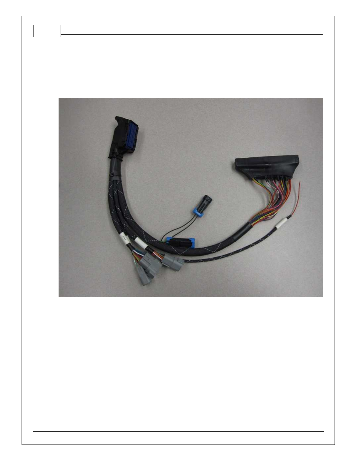
INFINITY ADAPTER HARNESS
Included with the 2001–2005 Honda K Series kit is an adapter harness. This is used to make the
connection between the AEM Infinity EMS and the Honda wiring harness plug and play. This is depicted
below with the 80-pin connector and the Honda header. There are also a few other integrated connectors
within this harness described below.
The gray Deutsch 6P DTM “LAMBDA” connector is for connecting a UEGO wideband Bosch LSU4.2
sensor (AEM 30-2001). The UEGO extension harness (AEM 30-3600) mates the adapter harness to the
sensor.
The gray Deutsch 4P DTM connector is used for “AEMNET”. AEMNet is an open architecture based on
CAN 2.0 which provides the ability for multiple enabled devices, such as dashboards, data loggers, etc.,
to easily communicate with one another through two twisted cables (CAN+/CAN-).
The black Delphi 2-pin “FLASH” connector is used for secondary hardware flashing. The included shunt
connector jumps the 2 wires together. Once initially flashed, the EMS is normally upgraded in the
software, not using this connector.
The red flying lead labeled “Battery+” is to be connected to a permanent +12V source. This source
should be independent of the ignition switch. The OEM Honda ECU does not have a permanent +12V
power pin, so this must be sourced separate from the OEM connector and should be protected with a 5A
fuse.
© 2014 AEM Performance Electronics
Page 5

The gray Deutsch 12P DTM “AUX” connector (shown
below) is used to adapt many common ancillary
inputs and outputs easily. Included in the kit are a
DTM 12P mating connector, 12 DTM terminals, and a
DTM 12P wedgelock. If used, these components will
need to be terminated by the installer or end user with
16–22awg wire (not included). Note: The pin
numbering is molded into the connector, as shown.
2001–2005 Honda K Series
5
© 2014 AEM Performance Electronics
Page 6

6
Dedicated
Dedicated and not reconfigurable
Assigned
Assigned but reconfigurable
Available
Available for user setup
Not Applicable
Not used in this configuration
Required
Required for proper function
Infinity
Pin
Infinity
Assignment
Honda
Pin
Honda Description
Infinity Hardware
Specification
Notes
1
LS 4
E26
Engine Speed Pulse
Lowside switch, 4A max, No
internal flyback diode.
The tachometer is pre-calibrated using a
combination of the LS4_Freq [Hz] 1-axis table
and the LS4_Duty [%] 2-axis table.
2
LS 5
B23
Variable Valv e Timing
Control
Lowside switch, 4A max with
internal flyback diode.
Inductive load should NOT
have f ull time power.
The Variable Valv e Timing Control is precalibrated using a combination of the LS5_Freq
[Hz] 1-axis table and the LS5_Duty [%] 2-axis
table.
3
LS 6C5---
Lowside switch, 4A max with
internal flyback diode.
Inductive load should NOT
have f ull time power.
See Wizard page "LowSide Assignment Tables"
for output assignment.
*Spare injector output Injector 7 for Inf inity 8h.
4
LS 7C4---
Lowside switch, 4A max, No
internal flyback diode.
See Wizard page "LowSide Assignment Tables"
for output assignment.
*Spare injector output Injector 8 for Inf inity 8h.
5
UEGO1
Heat
---
---
Bosch UEGO controller
Lowside switch f or UEGO heater control.
Connect to pin 4 of Bosch UEGO sensor. NOTE
that pin 3 of the Sensor is heater (+) and must be
power by a fused/switched 12V supply.
6
UEGO1 IA
---
---
Bosch UEGO controller
Trim Current signal. Connect to pin 2 of Bosch
UEGO sensor.
7
UEGO1 IP
---
---
Bosch UEGO controller
Pumping Current signal. Connect to pin 6 of
Bosch UEGO sensor.
8
UEGO1 UN
---
---
Bosch UEGO controller
Nernst Voltage signal. Connect to pin 1 of Bosch
UEGO sensor.
9
UEGO1 VM
---
---
Bosch UEGO controller
Virtual Ground signal. Connect to pin 5 of Bosch
UEGO sensor.
10
+12V Perm
Power
---
Voltage Back Up
Dedicated power management
CPU
Full time battery power. MUST be powered before
the ignition switch input is triggered. NOTE: Fused
battery power need to supply to the f ly ing lead on
the AEM adapter harness.
11
Coil 4
A27
Ignition Coil Pulse
No. 4
25 mA max source current
0–5V f alling edge f ire. Do NOT connect directly
to coil primary. Must use an ignitor or CDI that
accepts a f alling edge f ire signal.
12
Coil 3
A28
Ignition Coil Pulse
No. 3
25 mA max source current
0–5V f alling edge f ire. Do NOT connect directly
to coil primary. Must use an ignitor or CDI that
accepts a f alling edge f ire signal.
13
Coil 2
A29
Ignition Coil Pulse
No. 2
25 mA max source current
0–5V f alling edge f ire. Do NOT connect directly
to coil primary. Must use an ignitor or CDI that
accepts a f alling edge f ire signal.
P/N 30-3502
PINOUTS
Infinity Pinout
© 2014 AEM Performance Electronics
Page 7

2001–2005 Honda K Series
Infinity
Pin
Infinity
Assignment
Honda
Pin
Honda Description
Infinity Hardware
Specification
Notes
14
Coil 1
A30
Ignition Coil Pulse
No. 1
25 mA max source current
0–5V f alling edge f ire. Do NOT connect directly
to coil primary. Must use an ignitor or CDI that
accepts a f alling edge f ire signal.
15
---
---
---
---
---16---
---
---
---
---
17
VR0 (+) -
Crank
---
Dif f erential Variable
Reluctance Zero Cross
Detection
See Setup Wizard page Cam/Crank f or options.
18
VR0 (-) -
Crank
---
Dif f erential Variable
Reluctance Zero Cross
Detection
See Setup Wizard page Cam/Crank f or options.
19
VR1 (-) -
Cam
---
Dif f erential Variable
Reluctance Zero Cross
Detection
See Setup Wizard page Cam/Crank f or options.
20
VR1 (+) -
Cam
---
Dif f erential Variable
Reluctance Zero Cross
Detection
See Setup Wizard page Cam/Crank f or options.
21
LS 2
B6
Radiator Fan Control
Lowside switch, 4A max, No
internal flyback diode.
See Setup Wizard Page "LowSide Assignment
Tables" for output assignment and 2D table
"LS2_Duty [%]" f or on/of f activ ation.
22
LS 3
A12
Idle Air Control Valv e
Lowside switch, 4A max with
internal flyback diode.
Inductive load should NOT
have f ull time power.
See Setup Wizard page and corresponding Tables
for Idle Air Control.
23
Sensor GND
A10
Sensor Ground 1
Dedicated analog ground
Analog 0–5V sensor ground also found on aux
connector.
24
Sensor GND
A11
Sensor Ground 2
Dedicated analog ground
Analog 0–5V sensor ground.
25
Digital 0 -
Crank
A7
CKP
10K pullup to 12V. Will work
with ground or floating
switches.
See Setup Wizard page Cam/Crank f or options.
26
Digital 1 -
Cam1
A26
CMP2
10K pullup to 12V. Will work
with ground or floating
switches.
See Setup Wizard page Cam/Crank f or options.
27
Digital 2 -
Cam2
A25
CMP1
10K pullup to 12V. Will work
with ground or floating
switches.
See Setup Wizard page Cam/Crank f or options.
28
Digital 3 –
Flex Fuel
---
---
10K pullup to 12V. Will work
with ground or floating
switches.
Found on the Aux Connector. Input can be
assigned to different pins. See Setup Wizard
page Input Function Assignments for input
mapping options.
29
Digital 4 -
VSS#1
A18
Vehicle Speed Sensor
10K pullup to 12V. Will work
with ground or floating
switches.
See Setup Wizard page Vehicle Speed for
calibration constant.
30
Digital 5 -
---
---
10K pullup to 12V. Will work
with ground or floating
switches.
Found on the Aux Connector. Input can be
assigned to different pins. See Setup Wizard
page Input Function Assignments for input
mapping options.
31
Digital 6 -
---
10K pullup to 12V. Will work
with ground or floating
switches.
Input can be assigned to dif ferent pins. See
Setup Wizard page Input Function Assignments
for input mapping options.
*Coil 7 f or Infinity 8h
7
© 2014 AEM Performance Electronics
Page 8

8
Infinity
Pin
Infinity
Assignment
Honda
Pin
Honda Description
Infinity Hardware
Specification
Notes
32
Digital 7 -
---
---
10K pullup to 12V. Will work
with ground or floating
switches.
Input can be assigned to dif ferent pins. See
Setup Wizard page Input Function Assignments
for input mapping options.
*Coil 8 f or Infinity 8h
33
GNDA4Power Ground 1
Power Ground
Connects to chassis ground and AEMNet
34
CAN A -
---
---
Dedicated High Speed CAN
Transceiv er
4P DTM Connector found in AEM adapter
harness. Contact AEM f or additional information.
35
CAN A +
---
---
Dedicated High Speed CAN
Transceiv er
4P DTM Connector found in AEM adapter
harness. Contact AEM f or additional information.
36
CAN B -
---
---
Dedicated High Speed CAN
Transceiv er
Not used
37
CAN B +
---
---
Dedicated High Speed CAN
Transceiv er
Not used
38
Temp 1 -
Coolant
Temp
B8
Engine Coolant Temp
Sensor
12 bit A/D, 2.49K pullup to 5V
See "Coolant Temperature" Setup Wizard f or
selection.
39
Temp 2 - Air
Temp
(Manifold)
B17
Intake Air Temp
Sensor
12 bit A/D, 2.49K pullup to 5V
See "Air Temperature" Setup Wizard f or selection.
40
Temp 3 - Oil
Temp
---
---
12 bit A/D, 2.49K pullup to 5V
Found on the Aux Connector. 0–5V analog
signal.
41
LS 0
E1
Fuel Pump Relay
Lowside switch, 4A max, No
internal flyback diode.
Switched ground. Will prime for 2 seconds at key
on and activ ate if RPM > 0.
42
LS 1
---
---
Lowside switch, 4A max with
internal flyback diode.
Inductive load should NOT
have f ull time power.
Found in Aux Connector. See Setup Wizard page
Boost Control f or options. Monitor BoostControl
[%] channel for output state.
43
GNDA5Power Ground 2
Power Ground
Connect directly to battery ground.
44
Knock 0
A9
Knock Sensor
Dedicated knock signal
processor
See Knock in Setup Wizard for options.
45
Knock 1
Dedicated knock signal
processor
See Knock in Setup Wizard for options.
46
GND
Power Ground
Connect directly to battery ground.
47
12V_Relay _
Control
E7
Main Relay Control
0.7A max ground sink f or
external relay control
Will activ ate at key ON and at key OFF
according to the configuration settings.
48
+12V SW
(Ign Switch)
E9
Power Source 1
10K pulldown
Full time battery power must be av ailable at
infinity pin 10 before this input is triggered.
49
+5V_Out
A20
Sensor Voltage 1
Regulated, f used +5V supply
for sensor power
Analog sensor power and found on auxiliary
connector
50
+5V_Out
A21
Sensor Voltage 2
Regulated, f used +5V supply
for sensor power
Analog sensor power
51
Ana7 -
Throttle
A15
Throttle Position
Sensor
12 bit A/D, 100K pullup to 5V
0–5V analog signal. Do not connect signals
referenced to +12V as this can permanently
damage the ECU. See the Setup Wizard Set
Throttle Range page for automatic min/max
calibration.
52
Ana8 - Map
A19
MAP Sensor
12 bit A/D, 100K pullup to 5V
0–5V analog signal. See the Manifold Pressure in
Setup Wizard for setup and calibration.
53
Ana9 - Fuel
Press
---
---
12 bit A/D, 100K pullup to 5V
0–5V analog signal f ound on the Auxiliary
Connector
P/N 30-3502
© 2014 AEM Performance Electronics
Page 9

2001–2005 Honda K Series
Infinity
Pin
Infinity
Assignment
Honda
Pin
Honda Description
Infinity Hardware
Specification
Notes
54
VR2 (+) -
Driv en
Wheel
---
---
Dif f erential Variable
Reluctance Zero Cross
Detection
See Driven Wheel Speed Calibration in the Setup
Wizard Vehicle Speed page.
55
VR2 (-) -
Driv en
Wheel
---
---
Dif f erential Variable
Reluctance Zero Cross
Detection
See Driven Wheel Speed Calibration in the Setup
Wizard Vehicle Speed page.
56
VR3 (-) -
Tag Wheel
---
---
Dif f erential Variable
Reluctance Zero Cross
Detection
See Non Driv en Wheel Speed Calibration in the
Setup Wizard Vehicle Speed page.
57
VR3 (+) -
Tag Wheel
---
---
Dif f erential Variable
Reluctance Zero Cross
Detection
See Non Driv en Wheel Speed Calibration in the
Setup Wizard Vehicle Speed page.
58
HS Out 0
B15
VTEC solenoid Valve
0.7A max, High Side Solid
State Relay
+12V High Side Drive. See Setup Wizard Honda
VTEC page for options.
59
Stepper_1B
---
---
Automotive, Programmable
Stepper Driver, up to 28V and
±1.4A
Be sure that each internal coil of the stepper
motor is properly paired with the 1A/1B and 2A/2B
ECU outputs. Supports Bi-Polar stepper motors
only.
60
Stepper_2B
---
---
Automotive, Programmable
Stepper Driver, up to 28V and
±1.4A
Be sure that each internal coil of the stepper
motor is properly paired with the 1A/1B and 2A/2B
ECU outputs. Supports Bi-Polar stepper motors
only.
61
HBridge0_0
---
---
5.0A max Throttle Control
Hbridge Drive
62
HBridge0_1
---
---
5.0A max Throttle Control
Hbridge Drive
63
+12V
A2/B1
Main Power
Main Power
12 v olt power f rom relay powers the Infinity ,
Lambda sensor, and AEMNet
64
Injector 6
---
---
Saturated or peak and hold, 3A
max continuous
Spare injector output Injector 6
*No peak and hold injector for Infinity 8h
65
Injector 5
---
---
Saturated or peak and hold, 3A
max continuous
Spare injector output Injector 5
*No peak and hold injector for Infinity 8h
66
Injector 4 B2Injector 4
Saturated or peak and hold, 3A
max continuous
Injector 4
*No peak and hold injector for Infinity 8h
67
GND
---
---
Power Ground
Connects directly to ground
68
+12VA3Main Power
Main Power
12 v olt power f rom relay powers the Infinity
69
Ana19 -
APP2
---
---
12 bit A/D, 100K pullup to 5V
0–5V analog signal. Do not connect signals
referenced to +12V as this can permanently
damage the ECU.
70
Ana18 -
APP1
---
---
12 bit A/D, 100K pullup to 5V
0–5V analog signal. Do not connect signals
referenced to +12V as this can permanently
damage the ECU.
71
Ana16
- Mode SW
---
---
12 bit A/D, 100K pullup to 5V
0–5V analog signal. Use +5V Out pins as power
supply and Sensor Ground pins as the low
reference. Do not connect signals referenced to
+12V as this can permanently damage the ECU.
See the 1D lookup table 'Mode Switch' for input
state.
Also assignable to multiple functions. See Setup
Wizard f or details.
9
© 2014 AEM Performance Electronics
Page 10

10
Infinity
Pin
Infinity
Assignment
Honda
Pin
Honda Description
Infinity Hardware
Specification
Notes
72
Harness_Fla
sh_Enable
---
---
10K pulldown
Not usually needed for automatic f irmware
updates through Inf inity Tuner. If connection
errors occur during update, jump the 12V Flash
Connector bef ore proceeding with upgrade.
Disconnect the 12V Flash Connector af ter the
update.
73
Ana13 - Oil
Press
---
---
12 bit A/D, 100K pullup to 5V
0–5V analog signal f ound on the Auxiliary
Connector
74
Ana11 -
Shift SW
---
---
12 bit A/D, 100K pullup to 5V
0–5V analog signal f ound on the Auxiliary
Connector
75
Ana10
---
---
12 bit A/D, 100K pullup to 5V
0–5V analog signal f ound on the Auxiliary
Connector
76
Injector 3 B3Injector 3
Saturated or peak and hold, 3A
max continuous
Injector 3
*No peak and hold injector for Infinity 8h
77
Injector 2 B4Injector 2
Saturated or peak and hold, 3A
max continuous
Injector 2
*No peak and hold injector for Infinity 8h
78
Injector 1 B5Injector 1
Saturated or peak and hold, 3A
max continuous
Injector 1
*No peak and hold injector for Infinity 8h
79
Stepper_2A
---
---
Automotive, Programmable
Stepper Driver, up to 28V and
±1.4A
Be sure that each internal coil of the stepper
motor is properly paired with the 1A/1B and 2A/2B
ECU outputs. Supports Bi-Polar stepper motors
only.
80
Stepper_1A
---
---
Automotive, Programmable
Stepper Driver, up to 28V and
±1.4A
Be sure that each internal coil of the stepper
motor is properly paired with the 1A/1B and 2A/2B
ECU outputs. Supports Bi-Polar stepper motors
only.
Deutsch Pin
Infinity Pin
Wire Color
Pin Name
Default Pin Function
153Black
Analog_In_9
Fuel Pressure
240Black
Analog_In_Temp_3
Oil Temperature
323Black
AGND
Sensor Ground
449Black
+5V_OUT
Sensor +5V
573Black
Analog_In_13
Oil Pressure
630Black
Digital_In_5
Flex Fuel Sensor (Hz)
742Black
LS1
Boost Control
863Black
+12V
+12V
928Black
Digital_In_3
Turbo Speed
1071Black
Analog_In_16
Mode Switch
1175Black
Analog_In_10
???
1274Black
Analog_In_11
Shift Switch
P/N 30-3502
AUX Connector Pinout
© 2014 AEM Performance Electronics
Page 11

Miscellaneous Pinouts
LAMBDA 1
Deutsch Pin
Infinity Pin
Default Pin Function
18UEGO1 UN
26UEGO1 IA
363+12V
45UEGO1 Heat
59UEGO1 VM
67UEGO1 IP
AEMNet
Deutsch Pin
Infinity Pin
Default Pin Function
135CAN A+
234CAN A-
363+12V
433Ground
FLASH ENABLE
Delphi Pin
Infinity Pin
Default Pin Function
A10Permanent Power
B72Harness Flash Enable
2001–2005 Honda K Series
11
Honda Pin Numbering
© 2014 AEM Performance Electronics
Page 12

12
P/N 30-3502
Infinity Pin Numbering
Viewed From Wire Side
© 2014 AEM Performance Electronics
Page 13

2001–2005 Honda K Series
13
© 2014 AEM Performance Electronics
 Loading...