

Page 1

Installation Instructions for:
EPM for V8 Engines
WARNING:
This installation is not for the tuning novice nor the PC illiterate!
Use this system with EXTREME caution! Misuse of this product
can destroy your engine! If you are not well versed in engine
dynamics and the tuning of management systems or are not PC
,!
This product is legal in California for racing vehicles only and should
literate, please do not attempt the installation. Refer the
installation to a AEM trained tuning shop or call 800-423-0046
for technical assistance. You should also visit the AEM Tech
Forum at http://www.aempower.com
NOTE: AEM holds no responsibility for any engine damage that
results from the misuse of this product!
never be used on public highways.
ADVANCED ENGINE MANAGEMENT INC.
2205 126
© 2007 Advanced Engine Management, Inc.
th
Street Unit A Hawthorne, CA. 90250
Phone: (310) 484-2322 Fax: (310) 484-0152
Http://www.aempower.com
Instruction Part Number: 10-3252
Page 1 of 2
Page 2
The AEM Engine Position Sensor (EPM) replaces the stock V8 distributor and allows
the use of a coil on plug or wasted spark ignition system and can be used with any
aftermarket engine management system that recognizes the common 24 – 1 input for
crank and cam signal. The EPM provides precise engine position using dual zero
speed optical sensors. This offers the advantage of immediate signal generation when
the engine is cranked.
Read and understand these instructions BEFORE attempting to install this
product.
The EPM is outfitted from AEM with a “steel” distributor gear. If your cam requires the
use of a “bronze” gear please call AEM for further details. If you are not sure which
gear you need please double check with your cam manufacture first to verify the type of
gear needed for your cam.
1) Remove the Stock Distributor and install the AEM EPM. You can rotate the EPM so
that the cable routing is optimized for your application, timing will be set with the
EMS software.
2) EPM Wiring
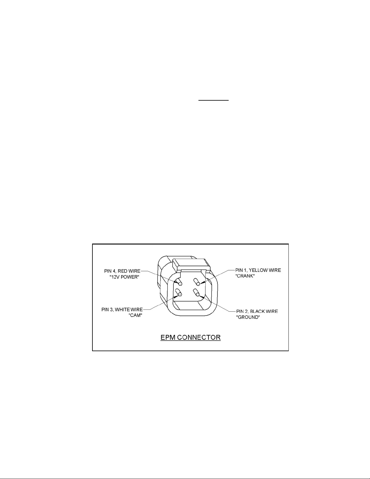
a) The EPM has a short cable with a 4 pin connector, supplied with the EPM is the
mating connector housing with 5 crimp terminals. The connector pinouts are
shown in figure 1.
Figure 1.
b)
The EPM puts out a 12V square wave, 24 crank signals and 1 short pulse cam
signal every 360 distributor degrees, see figure 2.
Page 2 of 3
Page 3
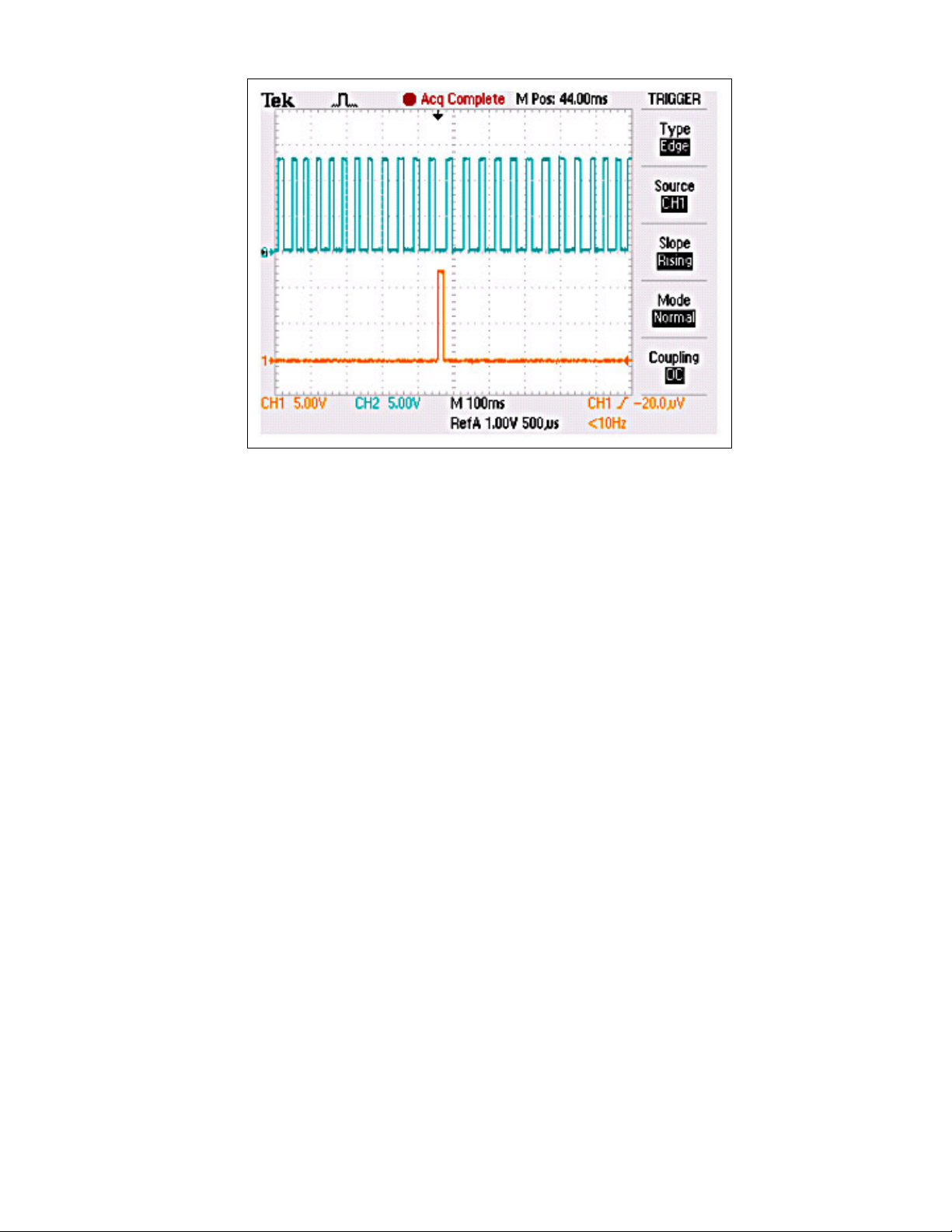
Figure 2.
Page 3 of 3
 Loading...