

Page 1
Instruction Manual
P/N 30-2906-0 AQ1 Data Logger
Harness Plug and Pin Kit
WARNING:
This installation is not for the electronic novice or the PC
illiterate! Use this system with EXTREME caution! If you are not
well versed in electronics and vehicle instrumentation or are not
PC literate, please do not attempt the installation. Refer the
,!
installation to an AEM trained tuning shop. A list of AEM
trained tuning shops is available at
http://www.aemelectronics.com/dealer_locator.php or by calling
800-423-0046. You should also visit the AEM Tech Forum at
http://www.aemelectronics.com
NOTE: AEM holds no responsibility for any engine damage that
results from the misuse of this product!
Note: This harness is only to be used
with the 30-2500 AQ1 Data Logger.
AEM Performance Electronics
th
2205 126
Phone: (310) 484-2322 Fax: (310) 484-0152
Street Unit A, Hawthorne, CA. 90250
http://www.aemelectronics.com
Instruction Part Number: 10-2906-0 Rev A
© 2011 AEM Performance Electronics
Page 2

The 30-2906-0 AQ1 Data Logger Harness Plug and Pin Kit is designed for applications
requiring a custom harness or for applications not using the hard wired analog,
analog/frequency, or switch-to-ground inputs. The plug and pin kit harness comes with
the necessary AEMnet, Power/Ground, RS232, USB, and CAN leads. The pin locations
for the analog, analog/frequency, and switch-to-ground inputs are not populated. A bag
of 20 terminals is included for connecting the analog, analog/frequency, and switch-toground inputs.
KIT CONTENTS
1 x AQ1 Data Logger Harness Plug and Pin Kit
1 x Bag of 20 Terminals
WIRING
Power Connections
RED (PERM PWR)- Connect to a fused (5 Amp) constant 12 volt power source.
RED (SWIGN) – Connect to a fused (5 Amp) switched 12 volt power source.
BLACK (BATT GND) – Connect to a clean power ground. (Do not connect to a sensor
ground)
AEMnet
AEMnet is an open architecture software and hardware interface based on the CAN 2.0
specification, which provides the ability for multiple enabled devices to easily
communicate with each other through a single cable. The hardware connection is made
through a Deutsch 4P DTM connector and contains 12 volt switched power and ground
(2A max) as well as the CAN data lines. Devices connected to the AEMnet transmit
data through this one connection and most of these devices receive power from this
same connection as well.
The following AEM products are currently AEMnet enabled:
Series 2 Engine Management System
EMS-4 Universal Standalone Engine Management System
4-Channel Wideband UEGO Controller
AQ-1 Data Logger
Plug the Deutsch 4-pin DTM connector on the AQ1 Data Logger harness into the
mating connector on other AEMnet compatible devices.
Page 2 10-2906-0 AQ1 Harness Instructions RevA 110707.doc
Page 3
INPUT SIGNALS
Analog 1-4 are 0-5V analog inputs with optional pull-up resistor for RTD/Thermistor-
style sensor. Examples: AEM gauges, MAP/pressure sensors, TPS/APP/shock
travel/load cell sensors, analog MAF sensors, any 2 wire RTD or thermistor style temp
sensor. See “Using the AQ1 Data Logger” for more information on configuring Inputs 1-
4. The corresponding wires in the harness for Analog 1-4 are Yellow and are labeled
INPUT 1, INPUT 2, INPUT 3 and, INPUT 4.
Analog/Frequency 5-8 are analog inputs for that can optionally measure frequency (05 V or 0-16 V) Examples: RPM, vehicle speed, frequency based MAF, injector duty
cycle, boost control solenoid, flow sensor, hall sensor, any 3 wire pressure sensor. See
“Using the AQ1 Data Logger” for more information on configuring Inputs 5-8. The
corresponding wires in the harness for Analog/Frequency 5-8 are Yellow and are
labeled INPUT 5, INPUT 6, INPUT 7, and INPUT 8.
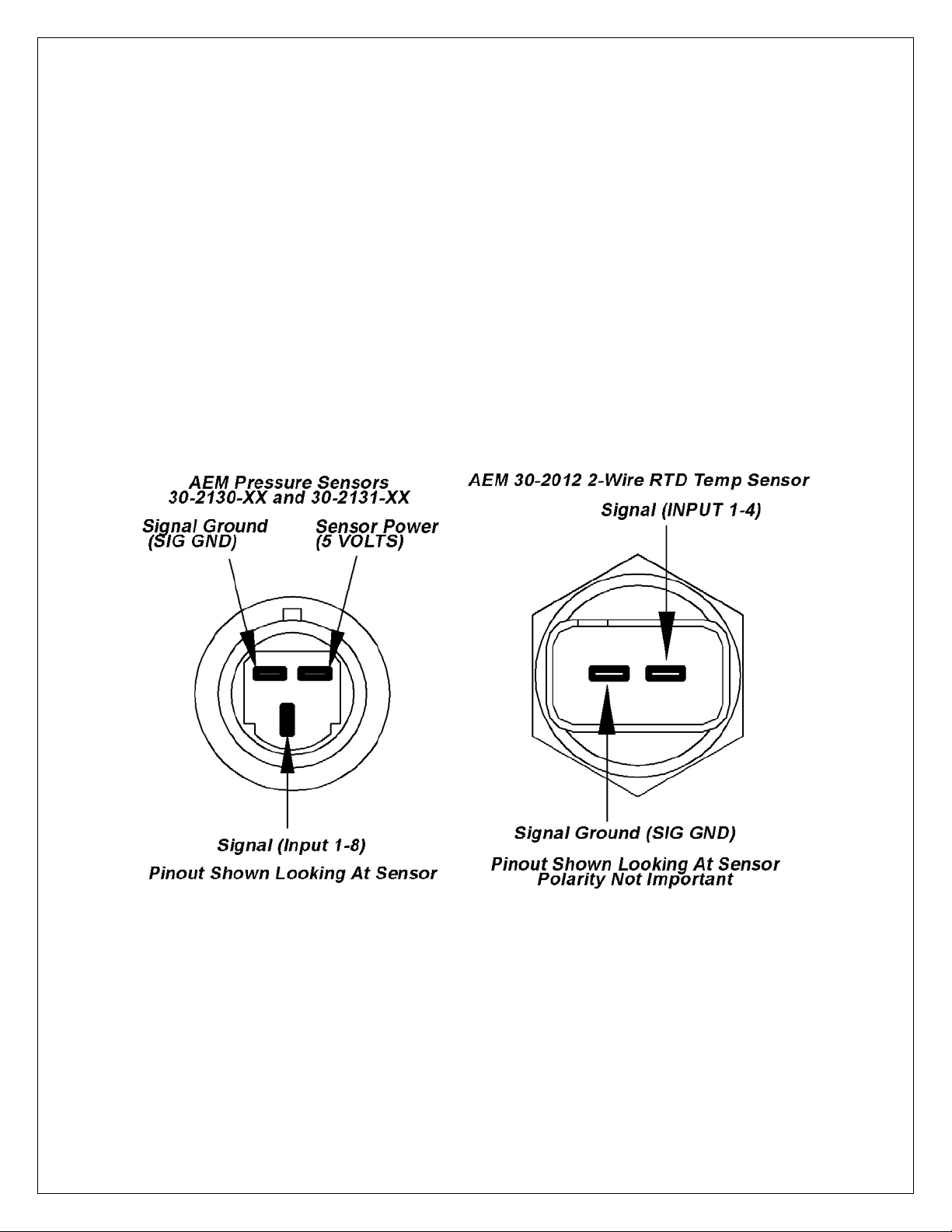
Connection diagrams are shown below for some of the more common sensors/signals
to be used with Inputs 1-4 and Inputs 5-8. See Figure 1.
Figure 1. AEM Pressure Sensors(Left) AEM Temp Sensor (Right)
Figure 2 below shows the connection for an engine speed signal using an AEM Twin
Fire CDI.
Page 3 10-2906-0 AQ1 Harness Instructions RevA 110707.doc
Page 4
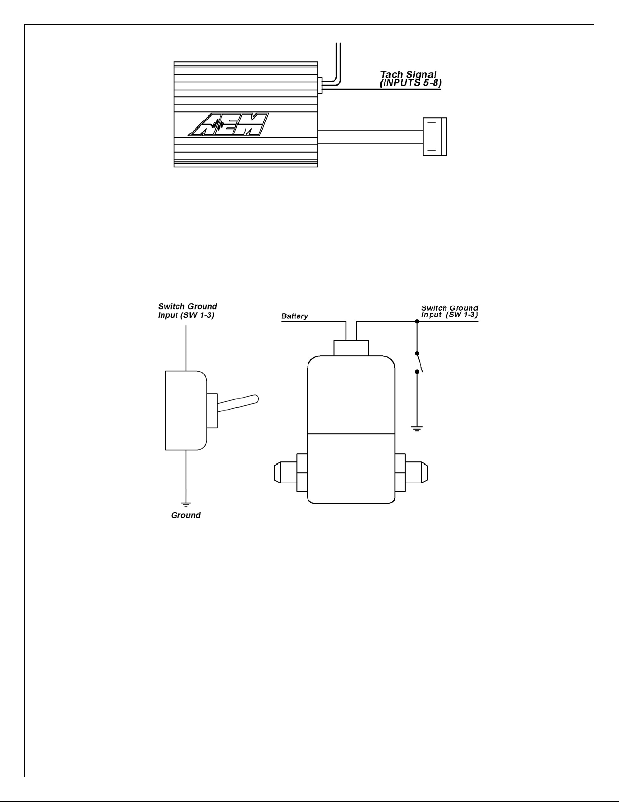
Figure 2. Engine RPM Signal From CDI
Digital 1-3 are switched to ground digital inputs, 16.5 V MAX tolerance.
Examples: Clutch/brake/cooling fan ground switch, nitrous solenoid ground or ground
switch input to start/stop Logger (Ground activated input). Figure 3 below shows wiring
diagrams for an on/off activation switch and a nitrous solenoid. The corresponding
wires in the harness for Digital 1-3 are Brown and are labeled SW 1, SW 2, and SW 3.
Figure 3. Activation Switch (Left) and Nitrous Solenoid (Right) Connections
SENSOR POWER
The AQ1 Data Logger has an internal low current 5 volt power supply that is used for
powering sensors that require a 5 volt excitation. The corresponding wires in the
harness are Red and are labeled 5 VOLTS.
SENSOR GROUND
The AQ1 Data Logger also has an internal low current sensor ground that is used for
sensors that require a signal ground. The corresponding wires in the harness are Black
and are labeled SIG GND.
Page 4 10-2906-0 AQ1 Harness Instructions RevA 110707.doc
Page 5

RS 232
The RS232 serial input on the AQ1 Data Logger is configurable to read either a
standard NMEA GPS data stream or the data stream from an AEM EMS. See “Using
the AQ1 Data Logger” for more information on configuring the RS232 input. The AQ1
Data Logger harness comes with a male DB9 connector. When connecting to an AEM
EMS, the male DB9 connector plugs directly into the mating connector on the back of
the AEM EMS. The pinout for a GPS connection is shown below in Figure 4. AEM
recommends using one of the Garmin GPS models listed below.
Garmin GPS 18x PC – 1 Hz model with DB9 connector and 12 volt power adapter
Garmin GPS18x 5Hz- 5 Hz OEM model, some wiring required.
Figure 4. Typical GPS Connection
CAN BUS 2
Not used with AQ1 Data Logger PN 30-2500
USB
The AQ1 Data Logger has two USB ports for easy connection and programming. The
AQ1 Data Logger receives low voltage power from the USB port, allowing users to
access the SD card and make configuration changes at all times, 12 volt power is not
necessary. The black remote mount USB port in the harness is designed for easy in
vehicle programming and data downloads. The USB port on the back of the enclosure
allows for easy bench top programming and data downloads when the module is
removed from the vehicle. See Figure 5 below.
Figure 5. AQ1 On-Board (Left) and Harness (Right) USB Ports
Page 5 10-2906-0 AQ1 Harness Instructions RevA 110707.doc
Page 6

30-2906-0 Connector Pinout
Pin Description Wire Stamping
1 Switched 12V SW IGN
2 Switch to Ground Digital Input 1 (16V Max) NOT POPULATED
3 Switch to Ground Digital Input 2 (16V Max) NOT POPULATED
4 Switch to Ground Digital Input 3 (16V Max) NOT POPULATED
5 Shield NOT POPULATED
6 Permanent 12V PERM PWR
7 Sensor Ground NOT POPULATED
8 Analog 1 (5V Max) NOT POPULATED
9 Analog 2 (5V Max) NOT POPULATED
10 Analog 3 (5V Max) NOT POPULATED
11 Analog 4 (5V Max) NOT POPULATED
12 Analog / Frequency 5 (5V / 16V Max) NOT POPULATED
13 Analog / Frequency 6 (5V / 16V Max) NOT POPULATED
14 Analog / Frequency 7 (5V / 16V Max) NOT POPULATED
15 Analog / Frequency 8 (5V / 16V Max) NOT POPULATED
16 RS-232 Tx (Output) N/A
17 RS-232 Rx (Input) N/A
18 RS-232/USB GND N/A
19 Power Ground BATT GND
20 Sensor 5V NOT POPULATED
21 Reserved N/A
22 Reserved N/A
23 Reserved N/A
24 Reserved N/A
25 Reserved N/A
26 Reserved N/A
27 AEMnet+ N/A
28 AEMnet- N/A
29 Reserved N/A
30 AEMnet Negative N/A
31 USB- N/A
32 USB+ N/A
33 CAN H N/A
34 CAN L N/A
35 Shield N/A
36 USB 5V N/A
Page 6 10-2906-0 AQ1 Harness Instructions RevA 110707.doc
Page 7

Figure 6. 36 Pin AQ1 Data Logger Connector, Wire Entry View
Crimping and Installing Terminals
Begin by cutting the strain relief tie wrap holding the
terminal bag as shown.
Page 7 10-2906-0 AQ1 Harness Instructions RevA 110707.doc
Using a sharp pick or probe, push in on the
locking tabs holding the outer retainer.
Page 8

Remove the retainer.
Use pick to pry open the retaining tabs
holding the backshell halves together
Open the shell to expose
the cavities.
Page 8 10-2906-0 AQ1 Harness Instructions RevA 110707.doc
Page 9

To remove a terminal, carefully pry up on the retaining
clip. Be careful as the clips can break if bent too far.
To add a new circuit, insert the terminal from the
back as shown until it clicks into place
Showing terminal fully seated.
Page 9 10-2906-0 AQ1 Harness Instructions RevA 110707.doc
Page 10

Delphi Part No: 12070948
Application: Unsealed Micro-Pack 100, Female only
Core and Insulation
Cable Range (mm2): 2.0-0.35
The tool is available in many places. One is shown below. Web
address – http://www.mouser.com AEM recommends using the proper
tool for all ECU terminations.
Image shows a properly crimped terminal. Top View.
Side View. After crimping, be sure to do a pull test
to make sure the terminal is properly installed.
Page 10 10-2906-0 AQ1 Harness Instructions RevA 110707.doc
Page 11

RECOMMENDED PARTS
30-51XX Analog Style Gauges
30-44XX Digital Style Gauges
30-2340 4 Channel UEGO Controller
30-4100 Digital Gauge Style UEGO Controller
30-5130 Analog Gauge Style UEGO Controller
30-2310 Inline UEGO Controller
30-2320 X-Wifi
30-2130-XX Stainless Steel Body Pressure Sensor
30-2131-XX Brass Body Pressure Sensor
30-2010 GM Style Inlet Air Temp Sensor
30-2011 GM Style Coolant Temp Sensor
30-2012 Fluid Temp Sensor, 1/8” NPT
If further tuning help is needed be sure to visit the video gallery or performance
electronics forum at www.aemelectronics.com for comprehensive instructional videos
and information.
WARRANTY
12 MONTH LIMITED WARRANTY
Advanced Engine Management Inc. warrants to the consumer that all AEM High Performance products will be free from defects in
material and workmanship for a period of twelve (12) months from date of the original purchase. Products that fail within this 12month warranty period will be repaired or replaced at AEM’s option, when determined by AEM that th e product failed due to defects
in material or workmanship. This warranty is limited to the repair or replacement of the AEM part. In no event shall this warranty
exceed the original purchase price of the AEM part nor shall AEM be responsible for special, incidental or consequential damages
or cost incurred due to the failure of this product. Warranty claims to AEM must be transportation prepaid and accompanied with
dated proof of purchase. This warranty applies only to the original purchaser of product and is non-transferable. All implied
warranties shall be limited in duration to the said 12 month warranty period. Improper use or installation, accident, abuse,
unauthorized repairs or alterations voids this warranty. AEM disclaims any liability for consequential damages due to breach of any
written or implied warranty on all products manufactured by AEM. Warranty returns will only be accepted by AEM when
accompanied by a valid Return Goods Authorization (RGA) number. Product must be received by AEM within 30 days of the date
the RGA is issued.
Please note that before AEM can issue an RGA for any product, it is first necessary for the installer or end user to contact the AEM
Performance Electronics tech line at 1-800-423-0046 to discuss the problem. Most issues can be resolved over the phone. Under
no circumstances should a system be returned or a RGA requested before the above process transpires.
Need additional help? Contact the AEM Performance Electronics tech department at
1-800-423-0046 or tech@aempower.com, or visit the AEM Performance Electronics
forum at http://forum.aempower.com/forum/
Page 11 10-2906-0 AQ1 Harness Instructions RevA 110707.doc
 Loading...