

Page 1

WARNING:
!
WARNING:
AEM Performance Electronics
P/N 30-2860 B Series COP
Conversion Kit
Instruction Manual
This product is legal in California for racing vehicles only and should never be
This installation is not for the tuning novice! Use this system
with EXTREME
dynamics and the tuning of engine management systems DO
NOT attempt the installation. Refer the installation to an AEM
trained tuning shop. A list of AEM trained tuning shops is
available at www.aemelectronics.com/dealer_locator.php or by
calling 800-423-0046.
NOTE: All supplied AEM calibrations, Wizards and other tuning
information are offered as potential starting points only. IT IS
THE RESPONSIBILITY OF THE ENGINE TUNER TO
ULTIMATELY CONFIRM THE CALIBRATION IS SAFE FOR ITS
INTENDED USE. AEM holds no responsibility for any engine
damage that results from the misuse or mistuning of this
product!
caution! If you are not well versed in engine
used on public highways.
WARNING: IT IS RECOMMENDED THAT TIMING BE CONFIRMED ON EACH
CYLINDER BEFORE ATTEMPTING TO START THE ENG INE!
2205 126th Street Unit A, Hawthorne, CA. 90250
Phone: (310) 484-2322 Fax: (310) 484-0152
http://www.aemelectronics.com
Instruction Part Number: 10-2860 Rev B
2011 AEM Performance Electronics
Page 2

KIT CONTENTS
1 x 35-2840 IGNITER W/ BRACKET
1 x 30-3255 HONDA EPM
4 x 30-2850 COIL
1 x 35-3860 B SERIES COP HARNESS
1 x 35-3861 EPM HARNESS
2 x #6 MOUNTING SCREW
2 x DIELECTRIC GREASE
INSTALLATION TIPS
1. Read through the entire manual and instructions before beginning the
installation.
2. Disconnect the negative battery cable(s) before beginning any work.
3. Maintain a clean and neat work area throughout the installation.
4. When raising or working under a vehicle, use properly rated stands/jacks.
5. Make sure all connectors are fully seated and inserted.
6. Make sure all components and cables are routed and installed away from any
direct heat sources or sharp objects.
TABLE OF CONTENTS
• Installation 2
• EMS/ECU Configuration 8
• Jumper Settings 12
• Syncing The EMS Timing 17
• EMS Pin Locations 18
• Connector Pinouts 19
• Factory Tachometer Setup 20
• Specifications 21
• Recommended Parts 21
• Replacement Parts 21
• Warranty 22
INSTALLATION
Removing the Factory Ignition
Remove the spark plug wires from the distributor and cylinder head. Unplug the
distributor from the factory wiring harness and remove the distributor from the engine.
The distributor is held in place by three mounting bolts. See Figure 1 below.
Page 2 10-2860 B Series COP Instructions RevB 111117
Page 3

Figure 1. Factory Distributor
Figure 2. Factory Distributor
Remove the retaining clip from the drive gear and remove the pin, drive gear, and shim.
Save the parts as they will be reused on the EPM. See Figures 2 and 3 below.
Page 3 10-2860 B Series COP Instructions RevB 111117
Page 4

Figure 3. Retaining Clip, Pin, Drive Gear, and Shim (left to right)
Figure 4. EPM with Shim, Drive Gear, Pin, and Retaining Clip Installed
Removed from Distribut or
AEM Engine Position Module (EPM)
Apply a small amount of clean engine oil to the shaft on the EPM and install the shim,
drive gear, pin, and retaining clip. See Figure 4 below.
Apply a small amount of clean engine oil to the O-ring on the EPM and install the EPM
as shown below in Figure 5. Secure the EPM using one of the stock distributor bolts
and washers.
Page 4 10-2860 B Series COP Instructions RevB 111117
Page 5

Figure 5. EPM Installed on B Series Engine
Figure 6. Coils Installed in Cylinder Head
Coils
With the factory plug wires removed, apply a small a mo unt o f diel ectric grease inside
the boot of the coils and install the coils on the spark plugs. Make sure the coils are
fully seated in the head and on the spark plugs. See Figure 6 below.
Page 5 10-2860 B Series COP Instructions RevB 111117
Page 6

B Series COP Harness
Figure 7. B Series COP Harness Connected to Coils
Figure 8. Igniter Mounted and Connected to B Series COP Harness
Lay the B Series COP harness over the cylinder head and connect the coil connectors
to the coils. See Figure 7 below. Make sure the connectors ar e fully seated and locked
into position.
Route the harness through the engine bay, away from any high heat sources and sharp
objects. The branch labeled “EMS” should be routed towards the ECU. The branch
labeled “Power” should be routed towards the power source.
Igniter
With the harness routed, find a suitable mounting location for the igniter and mount the
igniter. Two #6 screws are supplied for mounting the igniter to the firewall or engine
bay. Connect the two igniter connectors from the harness to the igniter. Make sure the
connectors are fully seated and locked into position. See Figure 8 below.
Page 6 10-2860 B Series COP Instructions RevB 111117
Page 7

EPM Harness
Figure 9. EPM Harness Connected to EPM
Connect the 4-pin connector on the EPM harness to the mating connector on t he EPM .
Make sure the connector is fully seated and locked into position. Route the harness
through the engine bay, away from any high heat sources and sharp objects, towards
the ECU. See Figure 9 below.
Wiring
EPM Harness
RED – EPM Power, Connect to 12 volts
BLACK – EPM Ground, connect to ground
GREEN – Crank Signal, connect to crank input on EMS/ECU
WHITE – Cam Signal, connect to cam input in EMS/ECU
DRAIN WIRE – Connect to power ground/drain in EMS/ECU
Page 7 10-2860 B Series COP Instructions RevB 111117
Page 8

B Series COP Harness
Figure 10. EPM Timing Pattern
RED (IGN) – Connect to switched, fused ( 15 A or greater) 12 volts
BLACK (GND) – Connect to ground
ORANGE (COIL 1) – Connect to Coil 1 Trigger in EMS/ECU
BLUE (COIL 2) – Connect to Coil 2 Trigger in EMS/ECU
PINK (COIL 3) – Connect to Coil 3 Trigger in EMS/ECU
GREY (COIL 4) – Connect to Coil 4 Trigger in EMS/ECU
EMS/ECU CONFIGURATION
Timing Patten
The EPM has a 24 and 1 timing pattern. There are 24 crank signals and one cam
signal for every engine cycle. Both output signals are 12 volt square waves. See
Figure 10 below.
EMS Wizard
The AEM EMS must be configured to accept the timing pattern from the EPM. In
AEMTuner, go to Wizards > Setup Wizard and select the AEM EPM. See Figure 11
below.
Page 8 10-2860 B Series COP Instructions RevB 111117
Page 9

Figure 11. Selecting the AEM EPM
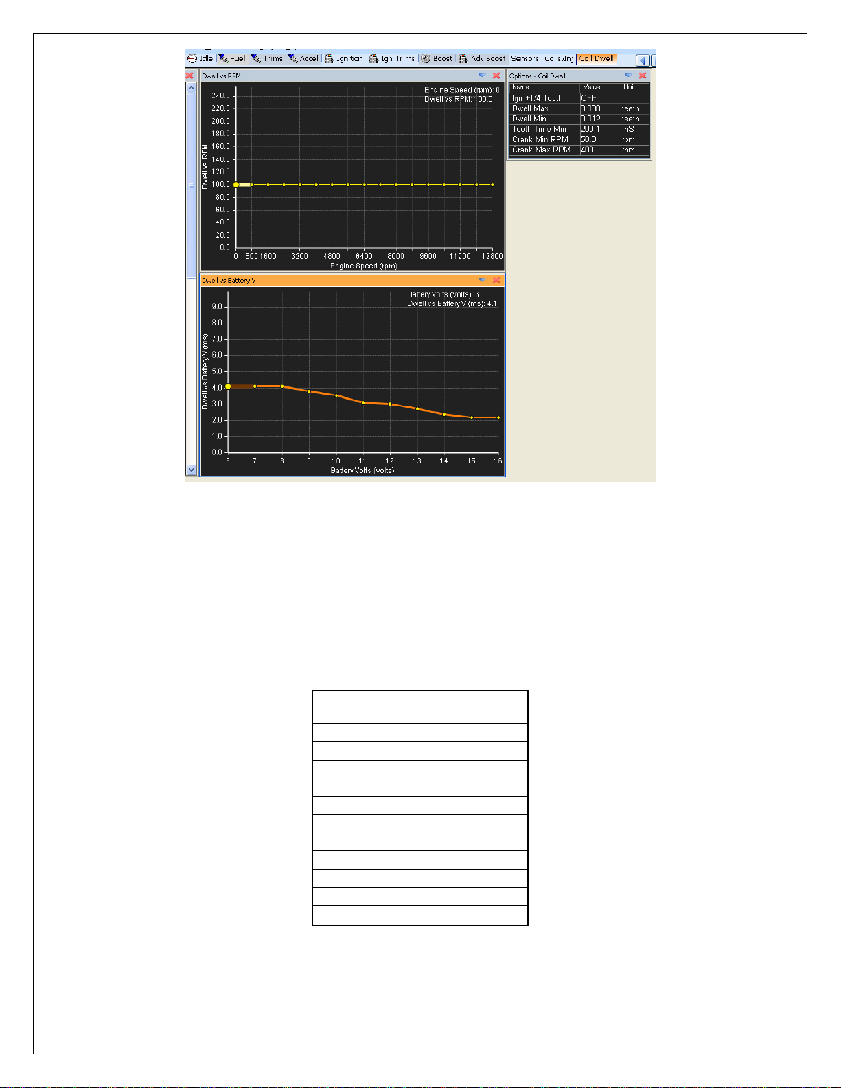
Figure 12. Coil and Injector Tab Showing Coil Settings
Coil Firing
In order for the EMS to fire each coil individually, the coils must be activated and
configured correctly in AEM Tuner. Click on the Coils and Injectors tab labeled Coils/Inj
and activate Coils 1 – 4. See Figure 12 below.
Page 9 10-2860 B Series COP Instructions RevB 111117
Page 10

The Coil Phasing sets the firing order of the coils and must match the Injector phasing.
Voltage
Dwell Time (mS)
16
2.2
15
2.2
14
2.4
13
2.7
12
3.0
11
3.1
10
3.5
9
3.8
8
4.1
7
4.1
6
4.1
Table 1. Series 2 Coil Dwell Settings for Dwell vs Battery V Table
For the example shown above in Figure 12, Coil 1 and Injector 1 both have a value of
12. The corresponding values for Coils and Injectors 2-4 also match. See the
advanced calibration notes on phasing included with the EMS for more information on
Coil and Injector phasing.
NOTE: IT IS RECOMMENDED THAT TIMING BE CONFIRMED ON ALL CYLINDERS
BEFORE ATTEMPTING TO START THE ENGINE!
Series 2 EMS Coil Dwell
The coil dwell settings are listed below in Table 1. Dwell times in excess of those listed
in Table 1 will not improve spark performance and may cause the igniter and/or coil to
overheat. Click on the coil dwell tab labeled Coil Dwell in AEM Tuner and adjust the
tables as shown in Figure 13 below. The values in Tabl e 1 sh ould be entered in the
Dwell vs Battery table. The Dwell vs RPM table should remain at 100% for all engine
speeds.
Page 10 10-2860 B Series COP Instructions RevB 111117
Page 11
Voltage
Dwell vs Batt
Volts
16
37
15
37
14
40
13
45
11
52
10
60
9
65
8
70 7 70 6 70
Figure 13. Series 2 Coil Dwell Settings
Table 2. Series 1 Dwell vs Batt Volts Table Values
Series 1 EMS Coil Dwell
Open the coil dwell template in AEM Pro by clicking on the ignition drop down menu and
going to Ignition>advanced ignition>coil dwell setup>coil dwell. Enter the values shown
below in Table 2 into the Dwell vs Batt Volts Table. The Dwell vs RPM Table should
remain constant at a value of 100. Enter a value of 30 into the Coil Dwell Factor option.
See Figure 14 below.
12 50
Page 11 10-2860 B Series COP Instructions RevB 111117
Page 12

Figure 15. Falling Edge Trigger Signal
Figure 14. Series 1 Coil Dwell Settings
ECU Trigger
The Four Channel Coil Driver included in this kit requires a 5V logic level trigger signal
that is configured to fire the coil on its falling edge. See Figure 15 below.
EMS Jumper Settings
The default factory jumper settings on the AEM EMS units will need to be changed in
order to work with the new signal requirements for the EPM and Igniter. The jumpers
are on the EMS circuit boards, making it necessary to remove the circuit boards from
the EMS enclosure. Remove the four screws from the front fac eplate of the EMS
enclosure and remov e the fac e pl ate . See Figure 16 below.
Page 12 10-2860 B Series COP Instructions RevB 111117
Page 13

Figure 16. Front View of EM S Showing Faceplate and Four Scr ews.
Figure 17. Bottom View of EMS Enclosure Showing Four Mounting Screws
Figure 18. Removing the Circuit Boards
Remove the four mounting screws on the bottom of the EMS enclosure. See Figure 17
below.
Slide the circuit boards out of the enclosure as shown below in Figure 18.
Page 13 10-2860 B Series COP Instructions RevB 111117
Page 14
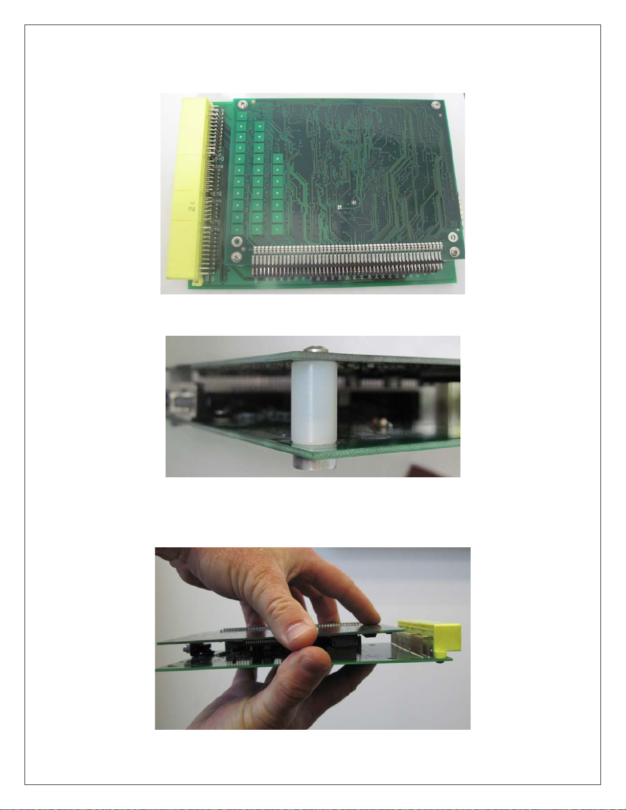
Remove the four screws and spacers that hold the two circuit boards together. The
Figure 19. Top View of Circuit Boards Showing Four Mounting Screws
Figure 20. Circuit Board Screw, Spacer, and Nut
Figure 21. Holding Circuit Boards for Separation
screws are threaded into round nuts on the bottom of the boards. See Figures 19 and
20 below.
With the four screws and spacers removed, the circuit boards can be separated. Hold
the circuit boards as shown below in Figure 21.
Page 14 10-2860 B Series COP Instructions RevB 111117
Page 15
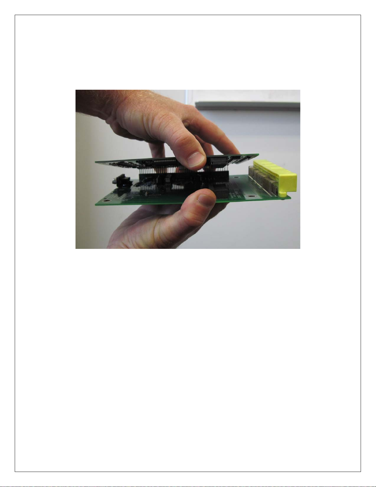
Figure 22. Separating the Circuit Boards
Separating the circuit boards requires some patience and caution. It works well to think
of the circuit board assembly as a hardcover book, with each circuit board being a
cover. Begin to separate the circuit boards, similar to opening a book. Close the circuit
boards and open again. This may take several tries. The connector between the circuit
boards will loosen up a little each time the circuit boards are opened and closed. See
Figure 22 below.
With the circuit boards separ at ed, locate the JPT and JPC jumpers. The JPT and JPC
jumpers each have three pins. A “jumper” is placed over two of the pins, connecting the
two pins together. The pins are numbered one, two and three. Pin one is designated
by a “1” on the circuit board. See Figures 23 and 24 below for examples of jumper
positions.
Page 15 10-2860 B Series COP Instructions RevB 111117
Page 16

Jumper
EMS 30-1040/30-6040
EMS 30-1050/30-6050
EMS 30-1060/30-6060
JPC1
1-2
1-2
1-2
JPC2
1-2
1-2
1-2
JPC3
1-2
1-2
1-2
JPC5
1-2
1-2
1-2
JPT1
1-2
1-2
1-2
JPT2
1-2
1-2
1-2
Table 3. EMS Jumper Position Settings
Figure 23. JPT1, 2, & 3 Jumpers Shown In 1-2
Figure 24. JPC jumpers Shown In 1-2 Position
position with JPT4 jumper shown in the
2-3 position for reference
Place the jumpers in the positions listed in Table 3. Only the jumpers listed below
should be moved for this installation.
JPC4 1-2 1-2 1-2
The EMS is ready to be reassembled after setting the jumpers. When reconnecting the
circuit boards, be sure all the pins are lined up correctly before fully inserting the
connector. With the pins correctly lined up, hold the EMS as shown below in Figure 25.
Page 16 10-2860 B Series COP Instructions RevB 111117
Page 17

Figure 26. Ignition Timing Sync Wizard
Figure 25. Reassembling the Circuit Boards
Once reassembled, install the EMS and reconnect the battery cables. Model specific
EMS instructions are included with each EMS kit and are available online in the
“Instructions and Manual” section of the AEM Performance Electronics Forum at
http://forum.aempower.com/forum/index.php?board=90.0. NOTE: THE STEPS
OUTLINED IN THE EMS INSTRUCTION MANUAL MUST BE FOLLOWED WHEN
INSTALLING THE EMS.
NOTE: IT IS RECOMMENDED THAT TIMING BE CONFIRMED ON EACH CYLINDER
BEFORE ATTEMPTING TO START THE ENGINE!
Syncing the EMS Timing
NOTE: THE EMS TIMING MUST BE SYNCED BEFORE TUNING
Start the engine and make whatever adjustments may be needed to sustain a safe and
reasonably smooth idle. Verify the ignition timing: Select Wizards>>Ignition Timing
Sync from the pull-down menu. Click the ‘Lock Ignition Timing’ checkbox and set the
timing to a safe and convenient value (for instance, 10 degrees BTDC), see Figure 26
below. Use a timing light and compare the physical timing numbers to the timing value
you selected. Use the Sync Adjustment Increase/Decrease buttons to make the
physical reading match the timing number you selected.
Page 17 10-2860 B Series COP Instructions RevB 111117
Page 18

EMS Pin Locations
PIN
EMS 30-6040
EMS 30-6050
EMS 30-6060
Harness
Harness
Coil 1
A21
C4
A20
NA
Orange
Coil 2
B6
C12
B7
NA
Blue
Coil 3
B3
C13
B9
NA
Pink
Coil 4
B4
C14
B10
NA
Grey
Cam
B11
C29
C4
White
NA
Pwr Gnd
A23 A24 A26 B2
B2 B10 B20 B22
A9 A10 A22 A23
Drain
NA
SW +12
A25 B1 C1
A21 B9
A11 A24 C6
Red
NA
Snsr Gnd
D21 D22
A7 A31 C7 C18 D9
D11 D12 D13
Black
NA
PIN
EMS 30-1040
EMS 30-1050
EMS 30-1060
EPM
Harness
COP Harness
Coil 2
B6
C12
B7
NA
Blue
Coil 3
B3
C13
B9
NA
Pink
Coil 5
B4
A1
B19
NA
Grey
Cam
B11
C29
C4
White
NA
Crank
B15
C8
C2
Green
NA
SW +12
A25 B1 C1
A21 B1 B9
A11 A24 C6
Red
NA
Snsr Gnd
A26 B2 D21 D22
A7 A31 C7 C18 D9
D11 D12 D13
Black
NA
Table 4. Series 2 EM S Pin Locations
Table 5. Series 1 EMS Pin Locations
Relevant pin locations for the 30-6040, 30-6050, and 30-6060 Series 2 EMS units are
shown below in Table 4.
EPM
Crank B15 C8 C2 Green NA
COP
Relevant pin locations for the 30-1040, 30-1050, and 30-1060 Series 1 EMS units are
shown below in Table 5. Take notice that the Series 1 EMS units use the #5 coil driver
on cylinder 4. The Series 2 EMS units use the #4 coil driver on cylinder 4.
Coil 1 A21 B13 A20 NA Orange
Pwr Gnd A23 A24 B2 B10 B20 B22 A9 A10 A22 A23 Drain NA
Page 18 10-2860 B Series COP Instructions RevB 111117
Page 19

CONNECTOR PINOUTS
Pin
Coil 1
Coil 2
Coil 3
Coil 4
1 +12V
Red
Red
Red
Red
2 Trigger
Orange
Blue
Pink
Grey
Pin
Description
Color
1
Coil 1 Negative
2
Coil 2 Negative
Blue
3
Coil 3 Negative
Pink
4
Coil 4 Negative
Grey
Pin
Description
Color
1
Coil 4 Trigger
Grey
2
Coil 3 Trigger
Pink
3
Ground
Black
4
Coil 2 Trigger
Blue
5
Coil 1 Trigger
Orange
Figure 27. Coil Connector Shown Looking at Pins
Figure 28. 4-Pin Igniter Connector Shown Looking at Pins
Figure 29. 5-Pin Igniter Connector Shown Looking at Pins
Pinouts for the EPM and B Series COP harness connectors are shown below.
Coil Connector
4-Pin Igniter Connector
Orange
5-Pin Igniter Connector
Page 19 10-2860 B Series COP Instructions RevB 111117
Page 20

PIN
EMS 30-6040
EMS 30-6050
EMS 30-6060
Tacho Output (LS 7)
C3
A19
C26
Power Source
A25 B1 C1
B1 B9
A11
Name
Value
Tacho Freq In
None
Tacho Freq Out
None
Tacho M
0
Tacho Output
LS7
Pin
Description
Wire Color
1
Crank
Green
2
Ground
Black
3
Cam
White
4
Power
Red
Figure 30. EPM Connector Shown Looking at Pins
Table 7. AEMTuner Tacho
Figure 30. AEMTuner Tacho Table settings
EPM Connector
FACTORY TACHOMETER Setup
Normally the distributor provides the input signal for the tachometer, but with the Honda
COP kit installed your car will no longer be using a distributor. The tachometers signal
wire is now left connected to nothing. There is however a simple fix for this provided by
the Series 2 EMS. The Series 2 EMS provides a signal output for the tachometer.
Connect the signal input from your tachometer to the appropriate pin for the EMS you
are using. Pin locations for the 30-6040, 30-6050, and 30-6060 Series 2 EMS units are
shown below in Table 6. The ground and power wires of your tachometer will still
remain connected as they were before.
Table 6. Series 2 EMS Pin Locations
Ensure that the tacho signal that will be generated by your EMS is set up correctly.
Open the calibration you are using in AEMTuner and view the “Tacho-Speedo” tab.
Make sure the “Tacho Options” table matches the settings shown below in Table 7 and
that the Tacho table looks like Figure 30 below.
Options settings
Page 20 10-2860 B Series COP Instructions RevB 111117
Page 21

SPECIFICATIONS
30-2860 B Series COP
Ignition Type
Inductive with Igniter
Ignition Channels
4
Timing Pattern
24 Crank, 1 Cam
Timing Pattern Signal
12 volt square wave
Ignition Trigger Signal
5 volt logic level falling edge trigger
Boost Level
Up to 15 psi
Max Dwell Time
See Table 1
Operating Voltage (nominal)
12 volts dc
RECOMMENDED PARTS
30-51XX Analog Style Gauges
30-44XX Digital Style Gauges
30-2340 4 Channel UEGO Controller
30-4100 Digital Gauge Style UEGO Con troller
30-5130 Analog Gauge Style UEGO Controller
30-2310 Inline UEGO Controller
30-2500 AQ1 Data Logger
30-2821 4 Channel Twin Fire CDI (Optional upgr ad e for higher boost levels abov e
15 psi, some wiring required)
REPLACEMENT PARTS
30-2840 4 Channel Igniter
30-3255 Honda EPM
30-2850 Coil
35-3860 B Series COP Harness
35-3861 EPM Harness
If further tuning help is needed be sure to visit the video gallery or performance
electronics forum at www.aemelectronics.com for comprehensive instructional videos
and information.
Page 21 10-2860 B Series COP Instructions RevB 111117
Page 22

WARRANTY
12 MONTH LIMITED WARRANTY
Advanced Engine Management Inc. warrants to t he consumer that all A EM High Performance products will be free from defects in
material and workmanship for a period of twelve (12) m onths from date of the original purchas e. Products that fail within this 12month warranty period will be repaired or replaced at A EM’s option, when determ i ned by AEM that the product f ailed due t o def ects
in material or workmanship. This warranty is limited to the repair or replacem ent of the AEM part. In no event shall thi s warranty
exceed the original purchase price of the AEM part nor shall AEM be responsible for special, incidental or consequential damages
or cost incurred due to the failure of this product. Warrant y claims to AEM must be transportation prepaid and accompanied with
dated proof of purchase. This warranty applies only to the original purchaser of product and is non-transferable. All implied
warranties shall be limited in duration to the said 12 month warranty period. Improper use or installation, accident, abuse,
unauthorized repairs or alterations voids this warranty. AEM disclaims any liability for consequential damages due to breach of any
written or implied warranty on all products manufactured by AEM. Warranty returns will only be accepted by AEM when
accompanied by a valid Return Goods Authorization (RGA) number. P roduct must be received by AEM within 30 days of the date
the RGA is issued.
Please note that before AEM c an issue an RGA f or any product , it is first necessary for the installer or end user to contact the AEM
Performance Electronics tech line at 1-800-423-0046 to discuss t he problem. Most issues can be resolved over the phone. Under
no circumstances should a system be returned or a RGA requested before the above process transpires.
Need additional help? Contact the AEM Performance Electronics tech department at
1-800-423-0046 or tech@aempower.com, or visit the AEM Performance Electronics
forum at http://forum.aempower.com/forum/
Page 22 10-2860 B Series COP Instructions RevB 111117
 Loading...