

Page 1
WARNING:
This installation is not for the
electronic novice
or the PC
AEM Performance Electronics
UEGO CONTROLLER
Instruction Manual
P/N 30-2340 4-CH WIDEBAND
!
illiterate! Use this system with EXTREME caution! If you are not
well versed in electronics and vehicle instrumentation or are not
PC literate, please do not attempt the installation. Refer the
installation to an AEM trained tuning shop. A list of AEM
trained tuning shops is available at
http://www.aemelectronics.com/dealer_locator.php or by calling
800-423-0046. You should also visit the AEM Tech Forum at
http://www.aemelectronics.com
NOTE: AEM holds no responsibility for any engine damage that
results from the misuse of this product!
2205 126th Street Unit A, Hawthorne, CA. 90250
Phone: (310) 484-2322 Fax: (310) 484-0152
http://www.aemelectronics.com
Instruction Part Number: 10-2340 Rev 05
2012 AEM Performance Electronics
Page 2
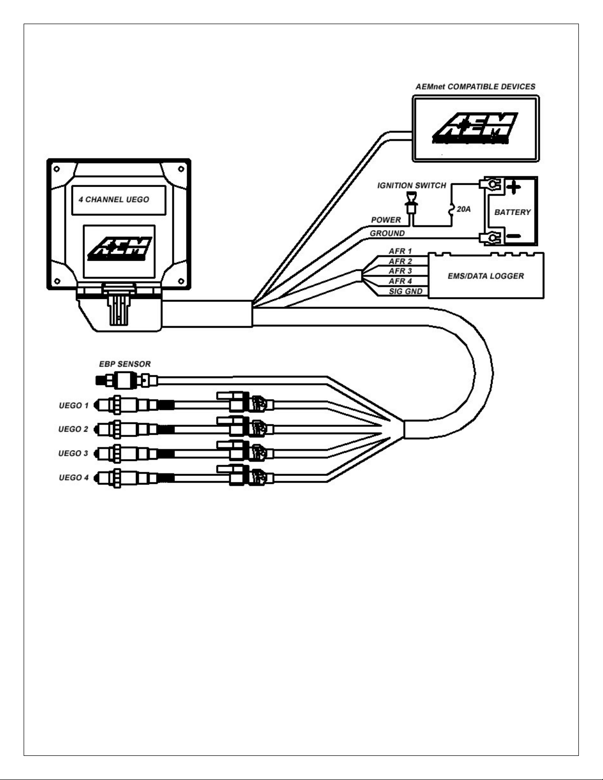
FIGURE 1. Wiring Diagram
Page 2 10-2340 Rev 05 121012
Page 3

KIT CONTENTS
1 x 35-2340 4 CH UEGO Module
1 x 35-2908 Wiring Harness
1 x 35-4008 UEGO Stainless Steel Bung
1 x 30-2001 UEGO Sensor
4 x 1-2059 6-32 Stainless Steel Hex Nut
4 x 1-2047 6-32 x 1 ¼ screw
1 x 10-2340 Installation Instructions
INSTALLATION TIPS
1. Read through the entire manual and instructions before beginning the
installation.
2. Disconnect the negative battery cable(s) before beginning any work.
3. Maintain a clean and neat work area through out the installation.
4. When raising or working under a vehicle, use properly rated stands/jacks.
5. Make sure all connectors are fully seated and inserted.
6. Make sure all components and cables are routed and installed away from any
direct heat sources or sharp objects.
TABLE OF CONTENTS
• Sensor Mounting…………………………………………..4
• Controller Mounting…………………………………….....4
• Power Connections…………………………………….....5
• AEMnet Connections…………………………....………...6
o AEMnet products………………………………..…6
o Series 2 EMS……………………………………....7
o Non AEM Products………………………………...8
• Cylinder Numbering and Mode Selection…………….....9
• Analog Outputs…………………………………………...11
o EMS………………………………………………...12
• Exhaust Back Pressure Compensation………………..14
• Indicator Lights……………………………………………14
• Series 2 EMS AEM Tuner Configuration………………15
• UEGO Connector Pinout………………………………...17
• Specifications……………………………………………..18
• Notes……………………………………………………….18
• Replacement/Optional Parts…………………………….18
• AEMnet message Structure……………………………..18
• Appendix A………………………………………………..19
• Warranty …………………………………………………..30
Page 3 10-2340 Rev 05 121012
Page 4
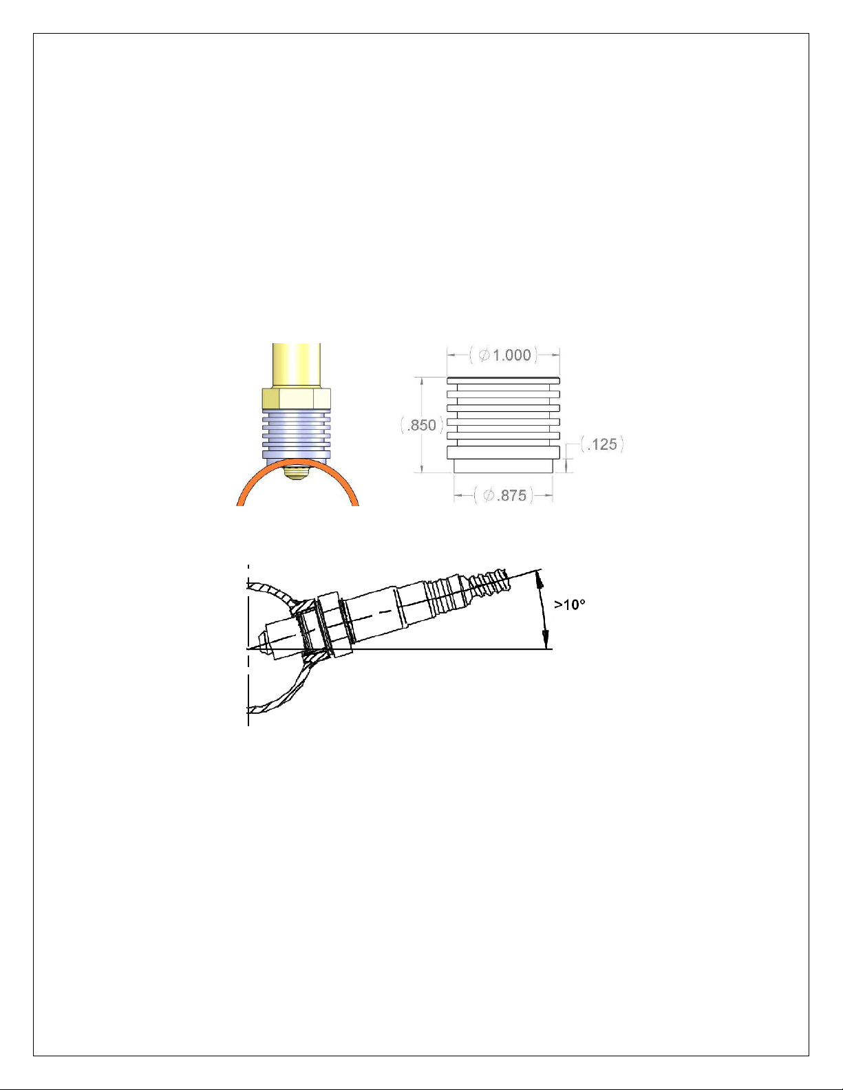
Sensor Mounting
FIGURE
2. Sensor Bung and Sensor Mounting
A high flow stainless steel weld-in sensor bung is supplied for sensor installation
(additional sensors & bungs are available 30-2063). The bung is specifically designed
so the sensor can provide accurate AFR readings with minimal flow intrusion and
survive extreme exhaust gas temperatures. Pick a mounting location(s) that allows for
easy access to the sensor(s). The sensor tip must be exposed to exhaust gas in order
to give accurate AFR readings. For thin wall tubing, drill a 15/16” hole and weld in the
bung. For thick wall tubing/ castings, drill a 1 1/16” hole and weld in the bung. The
sensor must be mounted at an angle of at least 10 degrees from horizontal in order to
prevent liquids from collecting in the sensor housing. See Figure 2 below. NOTE:
THE OPTIONAL AEM EBP (EXHAUST BACK PRESSURE) KIT (PART # 30-2064)
MUST BE USED IF SENSORS ARE MOUNTED PRE-TURBO.
Controller Mounting
Mount the controller using the supplied 6-32 x 1 ¼ stainless steel screws and nuts. See
Figure 3 and Figure 4 for mounting holes and footprint size.
Page 4 10-2340 Rev 05 121012
Page 5
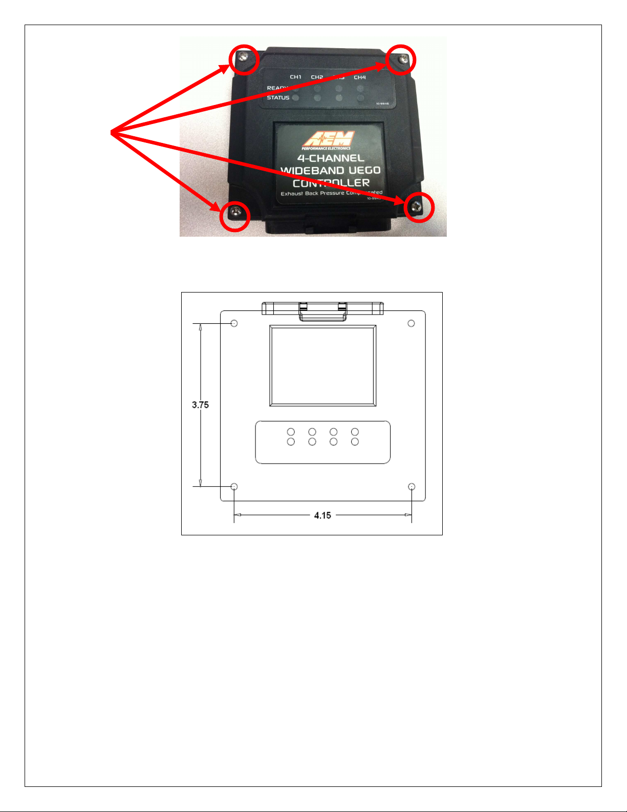
Mounting
Screws
FIGURE 3. Mounting Holes
FIGURE 4. Dimensions
POWER CONNECTIONS
RED – Connect to a switched, fused (20A) 12-volt power source that is on only
when the engine is running.
BLACK – Connect to a clean power ground.
Page 5 10-2340 Rev 05 121012
Page 6

AEMnet CONNECTIONS
AEMnet
AEMnet is an open architecture software and hardware interface based on the CAN 2.0
specification, which provides the ability for multiple enabled devices to easily
communicate with each other through a single cable. The hardware connection is made
through a Deutsch 4P DTM connector and contains 12 volt switched power and ground
(2A max) as well as the CAN data lines. Devices connected to the AEMnet transmit
data through this one connection and most of these devices receive power from this
same connection as well.
Connection via AEMnet/CAN is recommended as it is the easiest connection (only
needs one connection) and it eliminates the possibility of any analog voltage
losses/offsets commonly associated with analog inputs/outputs.
AEMnet PRODUCTS
The following AEM products are currently AEMnet enabled:
Series 2 Engine Management System
EMS-4 Universal Standalone Engine Management System
4-Channel Wideband UEGO Controller
AQ-1 Data Logger
Wideband Failsafe
Each 4 CH UEGO controller wiring harness has 2 connectors for accessing the AEMnet
(Refer to figure 5), one for accessing the network and the other for an expansion to
other devices.
FIGURE 5. AEMnet Connector
Page 6 10-2340 Rev 05 121012
Page 7
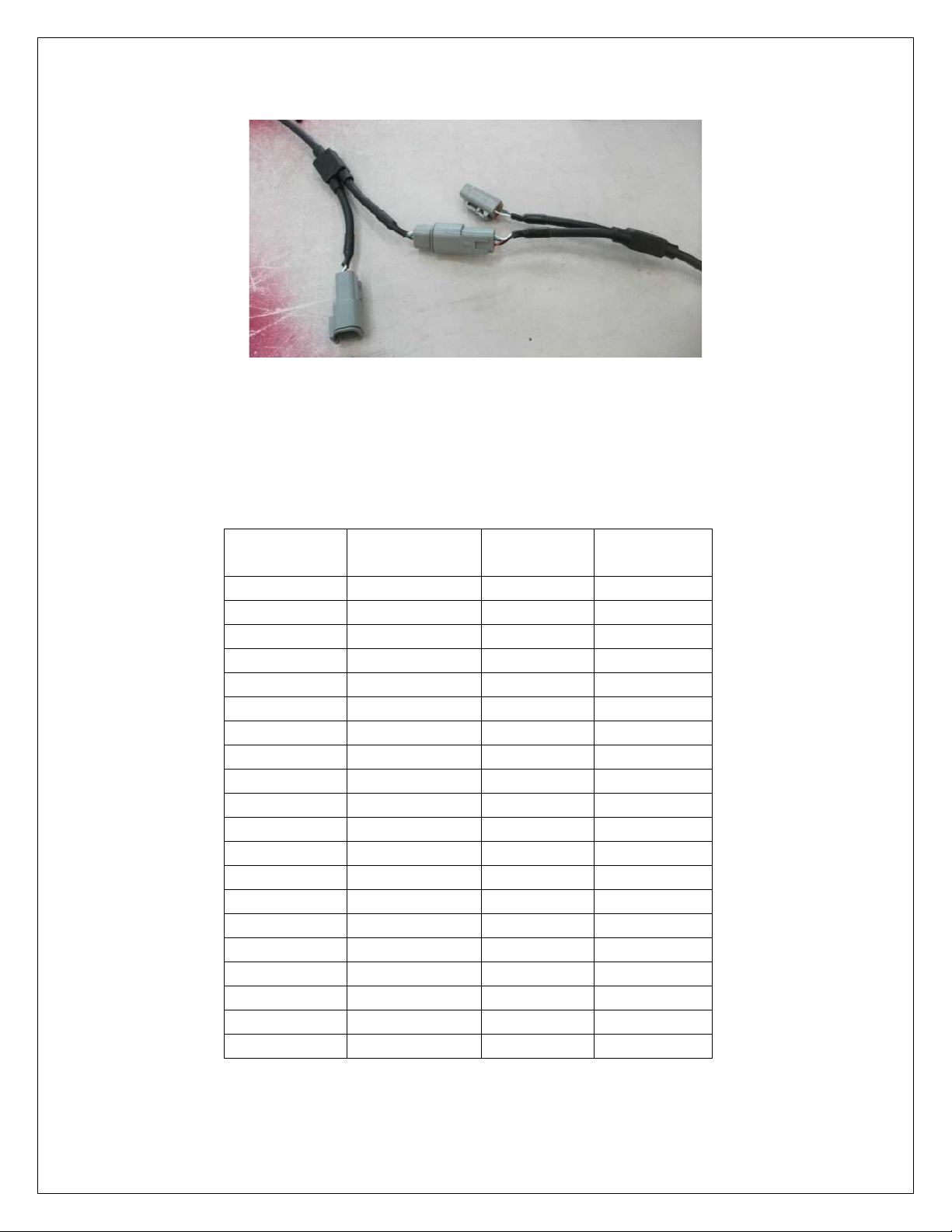
To join the AEM network, connect the Deutsch male connector to the female connector
of another AEM devices in the network (Figure 6).
FIGURE 6. AEMnet Cable Connection
SERIES 2 EMS
When connecting to a Series 2 EMS, an AEMnet branch will have to be added to the
factory harness. AEM has several AEMnet to Series 2 EMS adapters available. See
Table 1 below for a list of the part numbers and corresponding Series 2 EMS units.
AEM Series 2 AEMnet CAN1L CAN1H
EMS Adapter P/N Pin Location Pin Location
30-6030 30-3430 C22 C21
30-6040 30-3431 A22 C2
30-6050 30-3432 D14 D10
30-6051 30-3432 D14 D10
30-6052 30-3432 D14 D10
30-6053 30-3432 D14 D10
30-6060 30-3432 C28 C29
30-6100 30-3433 11A 12A
30-6101 30-3433 11A 12A
30-6300 30-3434 75 13
30-6310 30-3431 77 87
30-6311 30-3431 57/77 67/87
30-6320 30-3435 33 13
30-6600 30-3436 42 12
30-6601 30-3436 42 12
30-6610 30-3437 12 69
30-6611 30-3437 12 69
30-6620 30-3437 57 40
30-6820 30-3438 B29 B28
30-6821 30-3438 B29 B28
TABLE 1. EMS Adapter P/N & Pin Locations
Page 7 10-2340 Rev 05 121012
Page 8
NOTE: THE SERIES 2 EMS DOES NOT USE INFORMATION TRANSMITTED ON
AEMnet FOR 02 FEEDBACK. THE SERIES 2 EMS USES THE ANALOG INPUTS
FOR 02 FEEDBACK. SEE THE SECTION ON ANALOG INPUTS FOR INFORMATION
ON CONNECTING THE ANALOG INPUTS.
NON-AEM PRODUCTS
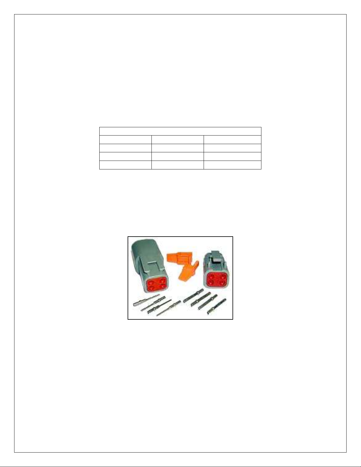
Each AEMnet connector has 4 pins. The AEMnet pinout is listed below in Table 2.
NOTE: Pin numbers are located at the back of the connector. Non-AEM devices can
connect to the AEMnet by connecting their CAN +/- wires to the CAN+/- wires on the
AEM network. The connectors are shown in Figure 7.
AEMnet Connector
Pin 1 White CAN +
Pin 2 Green CAN Pin 3 Red 12 Volts
Pin 4 Black Ground
Table 2. AEMnet Pinout
• Deutsch DTM04-4P (Receptacle connector)
• Deutsch 1060-20-0222 (Pins)
• Deutsch DTM06-4S (Plug connector)
• Deutsch 1062-20-0222 (Pins)
Figure 7. Connector Assembly
NOTE: the 4 CH UEGO controller has one terminating resistor. If an additional
terminating resistor is needed, one must be installed on the other device.
Page 8 10-2340 Rev 05 121012
Page 9
CYLINDER NUMBERING AND MODE SELECTION
MODE
3
MODE 4
MODE 2
MODE 4
MODE
3
MODE
5
MODE 1
MODE 1
MODE
5
MODE 2
MODE
3
MODE 4
MODE 7
MODE 6
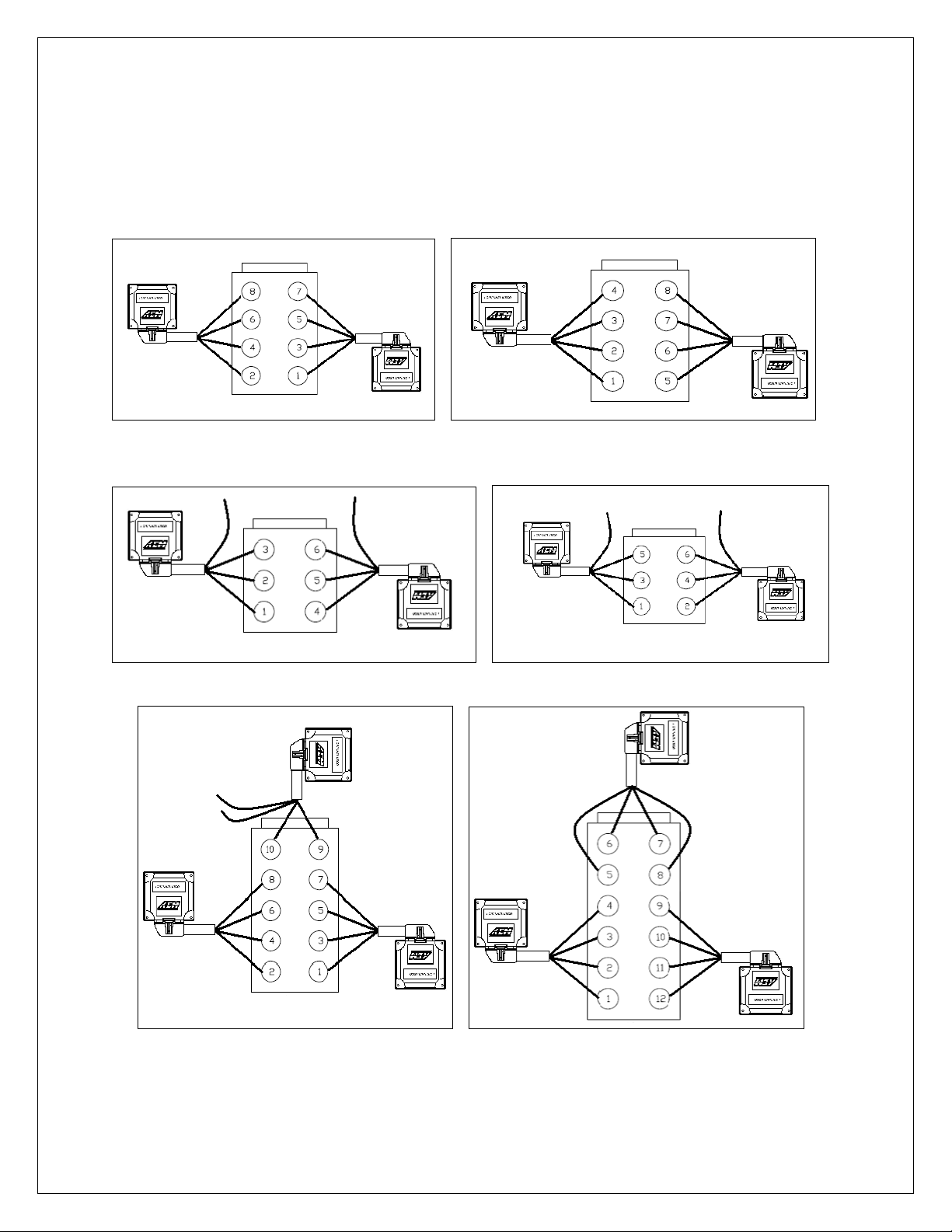
There are 7 different cylinder numbering combinations available on AEMnet. The
different combinations allow for easy installation and data analysis, and allow users to
connect up to three 4 Channel UEGO modules on AEMnet. See Table 3 and the
figures below for recommended connections on some of the more common engine
configurations.
CHEVROLET/ DODGE/ TOYOTA FORD
HONDA / ACURA NISSAN / TOYOTA
VIPER V12
Page 9 10-2340 Rev 05 121012
Page 10

MODE 1
MODE
7
MODE 6
4 CYLINDER 6 CYLINDER
FIGURE 8. 4 CH UEGO Controller Cylinder Numbering and Configuration Mode
MODE 1 MODE 2 MODE 3 MODE 4 MODE 5 MODE 6 MODE 7
UEGO 1 Cylinder1 Cylinder 5 Cylinder 1 Cylinder 2 Cylinder 9 Cylinder 1 Cylinder 4
UEGO 2 Cylinder 2 Cylinder 6 Cylinder 3 Cylinder 4 Cylinder 10 Cylinder 2 Cylinder 5
UEGO 3 Cylinder 3 Cylinder 7 Cylinder 5 Cylinder 6 Cylinder 11 Cylinder 3 Cylinder 6
UEGO 4 Cylinder 4 Cylinder 8 Cylinder 7 Cylinder 8 Cylinder 12
--- ---
TABLE 3. UEGO Sensor Cylinder Numbering
For example, Chevrolet big block engines require two 4 CH UEGO controllers. The first
unit connects to cylinders 2, 4, 6 and 8 using MODE 4 (see Table 2). UEGO 1 connects
to cylinder 2, UEGO 2 to cylinder 4, UEGO 3 to cylinder 6, and UEGO 4 to cylinder 8.
The second unit connects to cylinders 1, 3, 5 and 7 using MODE 3. UEGO 1 connects
to cylinder 1, UEGO 2 to cylinder 3, and so on.
Honda / Acura V6 engines also require two 4 CH UEGO controllers. As shown in
Figure 8, Mode 6 and 7 from Table 2 are used. UEGO 1, 2, and 3 of the first 4 CH
UEGO controller connects to cylinders 1, 2 and 3. UEGO 1, 2, 3 of the second unit go
to cylinder 4, 5 and 6. Unused channels can be left unconnected.
Cylinder Numbering Configuration Mode
NOTE: Only applicable when using AEMnet.
Configuration mode is selected during the power up sequence. By factory default the 4
CH UEGO controller is in MODE 1. There are three wires, CONFIG 1 (pink), CONFIG 2
(purple) and GROUND (yellow) under the sleeve on the wiring harness (Figure 9). To
change the mode, first make sure the 4 CH UEGO controller is powered off. Connect
CONFIG 1 to GROUND and power the 4 CH UEGO controller on. Tap CONFIG 2 to
the GROUND wire. The 4 Channel UEGO controller will jump to the next mode every
time the CONFIG 2 wire is tapped to the GROUND wire. The LEDs will illuminate to
Page 10 10-2340 Rev 05 121012
Page 11

show the selected mode. The number of Status/Error LED’s illuminated corresponds to
the mode selected. When a desired mode is selected, disconnect both CONFIG wires
from the GROUND wire. The mode will be saved in the controller and the LEDs of the
corresponding mode will blink three times. When more than one 4 CH UEGO
controller is connected to the net, the controllers must be in different modes.
Make sure that each controller is set into the correct mode. Upon powering up, the
number of LEDs corresponding to the mode will blink three times to indicate the mode.
For example, if in mode 7, 7 LED’s will blink 3 times.
FIGURE 9. Mode Configuration Wires
ANALOG OUTPUT
The analog output from the 4 CH UEGO controller is a linear dc voltage signal that
varies from 0.5 Vdc at 8.5:1 AFR Gasoline (0.58 Lambda) to 4.5Vdc at 18.0:1 AFR
Gasoline (1.22 Lambda). The signal is used for sending information to a data logger or
an engine management system such as the AEM EMS or F/IC. The transfer function
for the output is listed below.
AFR Gasoline = 2.375(V) + 7.3125
For example, if the output is 2.0 Vdc, the AFR is 12.06:1
2.375 * 2.0 + 7.3125 = 12.06
A table showing the analog output voltage and corresponding Air/Fuel ratios for some of
the common fuels is shown below in Table 3
.
AFR
VOLTS LAMBDA AFR GAS
0.50 0.58 8.5 3.7 5.6 5.2
0.71 0.61 9.0 3.9 5.9 5.5
0.92 0.65 9.5 4.1 6.3 5.8
1.13 0.68 10.0 4.4 6.6 6.1
METHANOL AFR E85
Page 11 10-2340 Rev 05 121012
AFR
ETHANOL
Page 12

1.34 0.71 10.5 4.6 6.9 6.4
1.55 0.75 11.0 4.8 7.3 6.7
1.76 0.78 11.5 5.0 7.6 7.0
1.97 0.82 12.0 5.2 7.9 7.3
2.18 0.85 12.5 5.4 8.2 7.7
2.39 0.88 13.0 5.7 8.6 8.0
2.61 0.92 13.5 5.9 8.9 8.3
2.82 0.95 14.0 6.1 9.2 8.6
3.03 0.99 14.5 6.3 9.6 8.9
3.11 1.00 14.7 6.4 9.7 9.0
3.24 1.02 15.0 6.5 9.9 9.2
3.45 1.05 15.5 6.7 10.2 9.5
3.66 1.09 16.0 7.0 10.6 9.8
3.87 1.12 16.5 7.2 10.9 10.1
4.08 1.16 17.0 7.4 11.2 10.4
4.29 1.19 17.5 7.6 11.5 10.7
4.50 1.22 18.0 7.8 11.9 11.0
TABLE 3. AFR Values
Outputs
The harness for the 4 Channel UEGO controller contains a bundle of 5 output wires.
The four white wires are labeled AFR 1, AFR 2, AFR 3, and AFR 4. The black wire is
labeled SIG GND. Connect the wires as listed below.
WHITE – Connect to Lambda + Input.
BLACK – Connect to sensor ground. Connect to power ground if sensor ground is not
available.
EMS Setup
Connect two WHITE AFR output + wires to O2 #1 and O2 #2 EMS analog input pins.
Connect the BLACK Analog Output – wire to the EMS sensor ground.
NOTE: The current version of EMS has only two input pins dedicated to O2 analog
inputs. To view the analog outputs from all four channels use spare analog inputs, i.e.,
EGT1 ~ 4.
Tuner Setup (Must use 01v22 firmware or newer)
With an EMS calibration open in the AEMTuner software, go to Wizards -> Setup
Wizard and choose Sensor: 02 #1 (AFR) and Sensor 02 #2 (AFR). Under Configuration
Name, choose AEM (4-Channel UEGO PN 30-2340) and click Apply. When the
configuration is set, as shown in figure 10, close the wizard.
Page 12 10-2340 Rev 05 121012
Page 13

FIGURE 10. Series 2 EMS / EMS – 4 Setup Wizard
Viewing Live Data
Open a new Channels Display in AEMTuner and add O2 #1 and O2 #2 channels. The
Channel Display, as shown in figure 11, will show the values in air-to-fuel ratio.
FIGURE 11. O2 #1 and O2 #2
When using spare analog inputs, the values will show in Volts. Use the following
equation to convert to air-to fuel ratio.
AFR Gasoline = 2.375 x voltage + 7.3125
Page 13 10-2340 Rev 05 121012
Page 14

EXHAUST BACK PRESSURE COMPENSATION
(OPTIONAL): MUST BE USED WHEN MOUNTING
UEGO SENSORS PRE-TURBO
UEGO sensors are extremely sensitive to pressure. Without an EBP kit (30-2064),
UEGO sensors mounted before the turbocharger will give inaccurate AFR readings due
to back pressure. When the EBP kit is installed correctly, the 4 CH UEGO controller will
output accurate AFR readings. UNDER NO CIRCUMSTANCES SHOULD UEGO
SENSORS BE MOUNTED PRE-TURBO WITHOUT USING THE EBP KIT.
When using multiple 4 Channel UEGO controllers on twin turbo or dual bank engines, it
is recommended that an EBP kit is used for each controller as back pressure levels can
vary per bank. When using multiple 4 Channel UEGO controllers on single turbo
engines, such as an inline 6, it is possible to share a single EBP source. To share a
single EBP source between multiple controllers, the green and black EBP wires for each
controller must be tied together as shown in Figures 12 and 13. Use extreme caution
when modifying the harness as improper connections may result in inaccurate AFR
readings. Be sure to cover all connections with moisture resistant heat shrink or
equivalent covering.
Figure 12. EBP Sensor Connector Figure 13. Cut & Spliced Wires
INDICATOR LIGHTS
The AEM 4 CH UEGO controller has eight indicator LEDs, one Status and one Ready
LED for each channel (Figure 14). Both Ready and Status LEDs flash during sensor
warm up. Once the UEGO sensor reaches operating temperature, usually within 30
seconds, the Status LED will turn off and the Ready LED will remain on solid. If a
UEGO sensor error is detected, analog output will switch to approximately +5V and both
LEDs will flash. The Status LED will flash on and off a number of times, followed by a
short pause, signifying an error code. The error codes are listed below in Table 4.
Page 14 10-2340 Rev 05 121012
Page 15

# of Flashes Fault Corrective Action
1 UEGO sensor heater open
2 Virtual Ground (VM) Error
3 Nernst Cell (UN) Error
4 Pump current (IP) Error
Check sensor cable for
broken wires/shorts
5 UEGO sensor heater time out
6 UEGO sensor heater short
Check electrical system
7 System voltage below 10 volts dc
for good connections
and proper function
TABLE 4. Error Codes
When there is no UEGO sensor connected to a particular channel, the Status LED of
that channel will remain on solid and the Ready LED will turn off after a few minutes.
The remaining channels with UEGO sensors connected will function properly.
When the exhaust back pressure kit (30-2064) is used, the 4 CH UEGO controller will
monitor exhaust back pressure. (NOTE: The 4 CH UEGO controller is designed to
work with a specific AEM pressure sensor. Do not use any sensor other than the
one included in the Exhaust Back Pressure Kit.) If a pressure sensor error is
detected, the 4 CH UEGO controller turns off all Ready LEDs and flashes Status LEDs,
starting with CH1 and ending with CH4. The analog output voltage level for all 4
channels switches to approximately +5V to signify an error.
Status Indicator
LED
FIGURE 14. Indicator Lights
Ready Indicator
LED
SERIES 2 EMS AEM TUNER CONFIGURATION FOR
AEMnet
Tuner Setup (Must use 01v22 firmware or newer)
In the AEMTuner EMS software, go to Wizards -> Setup Wizard. Under Wizard types,
click on Setup: CAN Receive. Choose a configuration and click Apply. There are
currently 4 configuration types available: MODE 1 + EBP Sensor, MODE 1 + MODE 2,
Page 15 10-2340 Rev 05 121012
Page 16

MODE 4 + MODE 5, and MODE 6 + MODE 7. Once this configuration is completed
Configuration Mode
Channels To Be Added
correctly, the word “Matched” will appear next to the configuration chosen, as shown in
Figure 15. Read the notes under Configuration Notes and close the window.
FIGURE 15. Series 2 EMS / EMS – 4 Setup Wizard
Viewing Live Data
Right-click in a blank space in the AEMTuner software and choose Add Channel
Display. From the list of available channels, select all the ones associated with the
selected configuration mode, as listed in Table 5. Figure 16 shows the Channel display
for “Mode 1 + EBP Sensor.”
Mode 1 + EBP Sensor
UEGO M1 Cyl 1 UEGO M1 Cyl 2
UEGO M1 Cyl 3 UEGO M1 Cyl 4
UEGO M1 EBP Sensor
Mode 1 + Mode 2
UEGO M1 Cyl 1 UEGO M2 Cyl 1
UEGO M1 Cyl 2 UEGO M2 Cyl 2
UEGO M1 Cyl 3 UEGO M2 Cyl 3
UEGO M1 Cyl 4 UEGO M2 Cyl 4
Mode 4 + Mode 5
UEGO M4 Cyl 1 UEGO M5 Cyl 1
UEGO M4 Cyl 2 UEGO M5 Cyl 2
UEGO M4 Cyl 3 UEGO M5 Cyl 3
UEGO M4 Cyl 4 UEGO M5 Cyl 4
Page 16 10-2340 Rev 05 121012
Page 17

Mode 6 + Mode 7
UEGO M6 Cyl 1 UEGO M7 Cyl 1
UEGO M6 Cyl 2 UEGO M7 Cyl 2
UEGO M6 Cyl 3 UEGO M7 Cyl 3
UEGO M6 Cyl 4 UEGO M7 Cyl 4
TABLE 5. Channel Selection
FIGURE 16. Mode 1 + EBP Sensor
UEGO CONNECTOR PIN-OUTS
The pin-out for the UEGO sensor connector is shown below in Figure 17.
FIGRE 17. UEGO Connector Pin-out
Page 17 10-2340 Rev 05 121012
Page 18

SPECIFICATIONS
4 CH UEGO Controller
Supply Current (nominal, peak) 3.2A, 10.5A peak
Differential Analog Outputs 4
Measuring Range: UEGO 8.5:1 to 18:1 AFR Gasoline, 0.58-1.22 Lambda
UEGO Sensor Accuracy 0.1 AFR
Operating Voltage (nominal) 8.5-15 volts dc
Harness & Connector Temp Limit: 105C
NOTES
If further tuning help is needed be sure to visit the video gallery or performance
electronics forum at www.aemelectronics.com for comprehensive instructional videos
and information.
The UEGO sensor contains a ceramic module and should not be subject to mechanical
or thermal shock or it may be damaged. The sensor is not designed for operation on
leaded fuels; doing so will dramatically shorten sensor life. Long term running in the rich
region (Lambda < 0.95) will shorten sensor life. High exhaust temperatures (over 850C)
will shorten sensor life. Engine oil consumption at a rate greater than 1 quart per 1,000
miles will shorten sensor life. With the UEGO Sensor installed, do not run the engine
without power applied to 4 CH UEGO controller.
REPLACEMENT/OPTIONAL UEGO CONTROLLER
COMPONENTS
30-2001 UEGO Sensor
35-4008 Stainless Steel UEGO Sensor Bung
30-2063 Sensor Kit with Stainless Bung
30-2064 Exhaust Back Pressure (EBP) Kit
30-343X AEMnet Adapter
AEMnet MESSAGE STRUCTURE
The 4 CH UEGO controller transmits two messages through the CAN network. The first
message contains Lambda values of all four channels and is transmitted every 10 ms.
The second message, transmitted every 40 ms, includes error flags, cylinder
configuration mode, EBP sensor readings and status. Messages are transmitted in 500
Kbps and use extended format message ID (29 bits). Appendix A shows entire
message protocols, including message IDs, number of bytes, data field, etc.
Page 18 10-2340 Rev 05 121012
Page 19

Lambda values are scaled up by 10,000 to retain decimal points. For example, if a
value of 9,876 is received as a lambda value from a 4 CH UEGO controller, the actual
lambda value is 0.9876. Use the following equation to derive the actual lambda value:
Actual Lambda value = Lambda from a message / 10,000
The back pressure value is scaled up by 100. Use the following equation to derive the
actual back pressure value.
Actual back pressure value (PSIg) = pressure from a message / 100
APPENDIX A
CAN MESSAGE PROTOCOL
CAN 2.0b, 29 bit, 500 kBit/sec
8 data bytes/message
All multi-byte data packed big endian unless specified (most significant byte transmitted first)
All bits numbered with the LSB = bit0, MSB = bit7
Message ID: 0x0000001F
Source: AEM 4 Channel UEGO set on MODE 1
Rate: 10ms continuous
Byte Label Data Type Scaling Offset Range
0
1
2
3
4
5
6
7
Message ID: 0x00000020
Source: AEM 4 Channel UEGO set on MODE 2
Rate: 10ms continuous
Byte Label Data Type Scaling Offset Range
0
1
2
3
4
5
6
7
Message ID: 0x00000021
Lambda 1 16 bit unsigned .0001 Lambda/bit 0 0 to 6.5535 Lambda
Lambda 2 16 bit unsigned .0001 Lambda/bit 0 0 to 6.5535 Lambda
Lambda 3 16 bit unsigned .0001 Lambda/bit 0 0 to 6.5535 Lambda
Lambda 4 16 bit unsigned .0001 Lambda/bit 0 0 to 6.5535 Lambda
Lambda 5 16 bit unsigned .0001 Lambda/bit 0 0 to 6.5535 Lambda
Lambda 6 16 bit unsigned .0001 Lambda/bit 0 0 to 6.5535 Lambda
Lambda 7 16 bit unsigned .0001 Lambda/bit 0 0 to 6.5535 Lambda
Lambda 8 16 bit unsigned .0001 Lambda/bit 0 0 to 6.5535 Lambda
Page 19 10-2340 Rev 05 121012
Page 20

Source: AEM 4 Channel UEGO set on MODE 3
Rate: 10ms continuous
Byte Label Data Type Scaling Offset Range
0
Lambda 1 16 bit unsigned .0001 Lambda/bit 0 0 to 6.5535 Lambda
1
2
Lambda 3 16 bit unsigned .0001 Lambda/bit 0 0 to 6.5535 Lambda
3
4
Lambda 5 16 bit unsigned .0001 Lambda/bit 0 0 to 6.5535 Lambda
5
6
Lambda 7 16 bit unsigned .0001 Lambda/bit 0 0 to 6.5535 Lambda
7
Message ID: 0x00000022
Source: AEM 4 Channel UEGO set on MODE 4
Rate: 10ms continuous
Byte Label Data Type Scaling Offset Range
0
Lambda 2 16 bit unsigned .0001 Lambda/bit 0 0 to 6.5535 Lambda
1
2
Lambda 4 16 bit unsigned .0001 Lambda/bit 0 0 to 6.5535 Lambda
3
4
Lambda 6 16 bit unsigned .0001 Lambda/bit 0 0 to 6.5535 Lambda
5
6
Lambda 8 16 bit unsigned .0001 Lambda/bit 0 0 to 6.5535 Lambda
7
Message ID: 0x00000023
Source: AEM 4 Channel UEGO set on MODE 5
Rate: 10ms continuous
Byte Label Data Type Scaling Offset Range
0
Lambda 9 16 bit unsigned .0001 Lambda/bit 0 0 to 6.5535 Lambda
1
2
Lambda 10 16 bit unsigned .0001 Lambda/bit 0 0 to 6.5535 Lambda
3
4
Lambda 11 16 bit unsigned .0001 Lambda/bit 0 0 to 6.5535 Lambda
5
6
Lambda 12 16 bit unsigned .0001 Lambda/bit 0 0 to 6.5535 Lambda
7
Message ID: 0x00000024
Source: AEM 4 Channel UEGO set on MODE 6
Rate: 10ms continuous
Byte Label Data Type Scaling Offset Range
0
Lambda 1 16 bit unsigned .0001 Lambda/bit 0 0 to 6.5535 Lambda
1
2
Lambda 2 16 bit unsigned .0001 Lambda/bit 0 0 to 6.5535 Lambda
3
Page 20 10-2340 Rev 05 121012
Page 21

4
5
6 --- --- --- --- --7 --- --- --- --- ---
Message ID: 0x00000025
Source: AEM 4 Channel UEGO set on MODE 7
Rate: 10ms continuous
Byte Label Data Type Scaling Offset Range
0
1
2
3
4
5
6 --- --- --- --- --7 --- --- --- --- ---
Message ID: 0x000001AF
Source: AEM 4 Channel UEGO set on MODE 1
Rate: 40ms continuous
Byte Label Data Type Scaling Offset Range
0 (bit0)
0 (bit1)
0 (bit2)
0 (bit3)
0 (bit4)
0 (bit5)
0 (bit6)
0 (bit7)
1 (bit0)
1 (bit1)
1 (bit2)
1 (bit3)
1 (bit4)
1 (bit5)
1 (bit6)
1 (bit7)
2 (bit0)
2 (bit1)
2 (bit2)
2 (bit3)
2 (bit4)
2 (bit5)
2 (bit6)
2 (bit7)
AFR 1 Heater Time-Out Error
AFR 2 Heater Time-Out Error
AFR 3 Heater Time-Out Error
Lambda 3 16 bit unsigned .0001 Lambda/bit 0 0 to 6.5535 Lambda
Lambda 4 16 bit unsigned .0001 Lambda/bit 0 0 to 6.5535 Lambda
Lambda 5 16 bit unsigned .0001 Lambda/bit 0 0 to 6.5535 Lambda
Lambda 6 16 bit unsigned .0001 Lambda/bit 0 0 to 6.5535 Lambda
AFR 1 Ready
AFR 1 Heater Open Error
AFR 1 VM Error
AFR 1 UN Error
AFR 1 IP Error
AFR 1 Heater Short Error
AFR 1 Overtemp Error
AFR 2 Ready
AFR 2 Heater Open Error
AFR 2 VM Error
AFR 2 UN Error
AFR 2 IP Error
AFR 2 Heater Short Error
AFR 2 Overtemp Error
AFR 3 Ready
AFR 3 Heater Open Error
AFR 3 VM Error
AFR 3 UN Error
AFR 3 IP Error
AFR 3 Heater Short Error
AFR 3 Overtemp Error
Boolean 0 = false, 1 = true 0 0/1
Boolean 0 = false, 1 = true 0 0/1
Boolean 0 = false, 1 = true 0 0/1
Boolean 0 = false, 1 = true 0 0/1
Boolean 0 = false, 1 = true 0 0/1
Boolean 0 = false, 1 = true 0 0/1
Boolean 0 = false, 1 = true 0 0/1
Boolean 0 = false, 1 = true 0 0/1
Boolean 0 = false, 1 = true 0 0/1
Boolean 0 = false, 1 = true 0 0/1
Boolean 0 = false, 1 = true 0 0/1
Boolean 0 = false, 1 = true 0 0/1
Boolean 0 = false, 1 = true 0 0/1
Boolean 0 = false, 1 = true 0 0/1
Boolean 0 = false, 1 = true 0 0/1
Boolean 0 = false, 1 = true 0 0/1
Boolean 0 = false, 1 = true 0 0/1
Boolean 0 = false, 1 = true 0 0/1
Boolean 0 = false, 1 = true 0 0/1
Boolean 0 = false, 1 = true 0 0/1
Boolean 0 = false, 1 = true 0 0/1
Boolean 0 = false, 1 = true 0 0/1
Boolean 0 = false, 1 = true 0 0/1
Boolean 0 = false, 1 = true 0 0/1
Page 21 10-2340 Rev 05 121012
Page 22

3 (bit0)
3 (bit1)
3 (bit2)
3 (bit3)
3 (bit4)
3 (bit5)
3 (bit6)
3 (bit7)
4 (bit0)
4 (bit1)
4 (bit2)
4 (bit3)
4 (bit4)
4 (bit5)
4 (bit6)
4 (bit7)
5 (bit0)
5 (bit1)
5 (bit2)
5 (bit3)
5 (bit4)
5 (bit5)
5 (bit6)
5 (bit7)
6
7
Message ID: 0x000001B0
Source: AEM 4 Channel UEGO set on MODE 2
Rate: 40ms continuous
Byte Label Data Type Scaling Offset Range
0 (bit0)
0 (bit1)
0 (bit2)
0 (bit3)
0 (bit4)
0 (bit5)
0 (bit6)
0 (bit7)
1 (bit0)
1 (bit1)
1 (bit2)
1 (bit3)
1 (bit4)
1 (bit5)
1 (bit6)
AFR 4 Ready
AFR 4 Heater Open Error
AFR 4 VM Error
AFR 4 UN Error
AFR 4 IP Error
AFR 4 Heater Time-Out Error
AFR 4 Heater Short Error
AFR 4 Overtemp Error
UEGO Low Voltage Error
EBP sensor ready
EBP sensor Error Low Volt
EBP sensor detected
CAN Config Mode
CAN Config Mode
CAN Config Mode
CAN Config Mode
Reserved
Reserved
Reserved
Reserved
Sensor 4 Heating up
Sensor 3 Heating up
Sensor 2 Heating up
Sensor 1 Heating up
Exhaust Pressure 1 16 bit unsigned .001 psig/bit 0 0 to 655.35 psig
AFR 5 Ready
AFR 5 Heater Open Error
AFR 5 VM Error
AFR 5 UN Error
AFR 5 IP Error
AFR 5 Heater Time-Out Error
AFR 5 Heater Short Error
AFR 5 Overtemp Error
AFR 6 Ready
AFR 6 Heater Open Error
AFR 6 VM Error
AFR 6 UN Error
AFR 6 IP Error
AFR 6 Heater Time-Out Error
AFR 6 Heater Short Error
Boolean 0 = false, 1 = true 0 0/1
Boolean 0 = false, 1 = true 0 0/1
Boolean 0 = false, 1 = true 0 0/1
Boolean 0 = false, 1 = true 0 0/1
Boolean 0 = false, 1 = true 0 0/1
Boolean 0 = false, 1 = true 0 0/1
Boolean 0 = false, 1 = true 0 0/1
Boolean 0 = false, 1 = true 0 0/1
Boolean 0 = false, 1 = true 0 0/1
Boolean 0 = false, 1 = true 0 0/1
Boolean 0 = false, 1 = true 0 0/1
Boolean 0 = false, 1 = true 0 0/1
Boolean 0 = false, 1 = true 0 0/1
Boolean 0 = false, 1 = true 0 0/1
Boolean 0 = false, 1 = true 0 0/1
Boolean 0 = false, 1 = true 0 0/1
Boolean 0 = false, 1 = true 0 0/1
Boolean 0 = false, 1 = true 0 0/1
Boolean 0 = false, 1 = true 0 0/1
Boolean 0 = false, 1 = true 0 0/1
Boolean 0 = false, 1 = true 0 0/1
Boolean 0 = false, 1 = true 0 0/1
Boolean 0 = false, 1 = true 0 0/1
Boolean 0 = false, 1 = true 0 0/1
Boolean 0 = false, 1 = true 0 0/1
Boolean 0 = false, 1 = true 0 0/1
Boolean 0 = false, 1 = true 0 0/1
Boolean 0 = false, 1 = true 0 0/1
Boolean 0 = false, 1 = true 0 0/1
Boolean 0 = false, 1 = true 0 0/1
Boolean 0 = false, 1 = true 0 0/1
Boolean 0 = false, 1 = true 0 0/1
Boolean 0 = false, 1 = true 0 0/1
Boolean 0 = false, 1 = true 0 0/1
Boolean 0 = false, 1 = true 0 0/1
Boolean 0 = false, 1 = true 0 0/1
Boolean 0 = false, 1 = true 0 0/1
Boolean 0 = false, 1 = true 0 0/1
Boolean 0 = false, 1 = true 0 0/1
Page 22 10-2340 Rev 05 121012
Page 23

1 (bit7)
2 (bit0)
2 (bit1)
2 (bit2)
2 (bit3)
2 (bit4)
2 (bit5)
2 (bit6)
2 (bit7)
3 (bit0)
3 (bit1)
3 (bit2)
3 (bit3)
3 (bit4)
3 (bit5)
3 (bit6)
3 (bit7)
4 (bit0)
4 (bit1)
4 (bit2)
4 (bit3)
4 (bit4)
4 (bit5)
4 (bit6)
4 (bit7)
5 (bit0)
5 (bit1)
5 (bit2)
5 (bit3)
5 (bit4)
5 (bit5)
5 (bit6)
5 (bit7)
6
7
Message ID: 0x000001B1
Source: AEM 4 Channel UEGO set on MODE 3
Rate: 40ms continuous
Byte Label Data Type Scaling Offset Range
0 (bit0)
0 (bit1)
0 (bit2)
0 (bit3)
0 (bit4)
0 (bit5)
AFR 6 Overtemp Error
AFR 7 Ready
AFR 7 Heater Open Error
AFR 7 VM Error
AFR 7 UN Error
AFR 7 IP Error
AFR 7 Heater Time-Out Error
AFR 7 Heater Short Error
AFR 7 Overtemp Error
AFR 8 Ready
AFR 8 Heater Open Error
AFR 8 VM Error
AFR 8 UN Error
AFR 8 IP Error
AFR 8 Heater Time-Out Error
AFR 8 Heater Short Error
AFR 8 Overtemp Error
UEGO Low Voltage Error
EBP sensor ready
EBP sensor Error Low Volt
EBP sensor detected
CAN Config Mode
CAN Config Mode
CAN Config Mode
CAN Config Mode
Reserved
Reserved
Reserved
Reserved
Sensor 8 Heating up
Sensor 7 Heating up
Sensor 6 Heating up
Sensor 5 Heating up
Exhaust Pressure 2 16 bit unsigned .001 psig/bit 0 0 to 655.35 psig
AFR 1 Ready
AFR 1 Heater Open Error
AFR 1 VM Error
AFR 1 UN Error
AFR 1 IP Error
AFR 1 Heater Time-Out Error
Boolean 0 = false, 1 = true 0 0/1
Boolean 0 = false, 1 = true 0 0/1
Boolean 0 = false, 1 = true 0 0/1
Boolean 0 = false, 1 = true 0 0/1
Boolean 0 = false, 1 = true 0 0/1
Boolean 0 = false, 1 = true 0 0/1
Boolean 0 = false, 1 = true 0 0/1
Boolean 0 = false, 1 = true 0 0/1
Boolean 0 = false, 1 = true 0 0/1
Boolean 0 = false, 1 = true 0 0/1
Boolean 0 = false, 1 = true 0 0/1
Boolean 0 = false, 1 = true 0 0/1
Boolean 0 = false, 1 = true 0 0/1
Boolean 0 = false, 1 = true 0 0/1
Boolean 0 = false, 1 = true 0 0/1
Boolean 0 = false, 1 = true 0 0/1
Boolean 0 = false, 1 = true 0 0/1
Boolean 0 = false, 1 = true 0 0/1
Boolean 0 = false, 1 = true 0 0/1
Boolean 0 = false, 1 = true 0 0/1
Boolean 0 = false, 1 = true 0 0/1
Boolean 0 = false, 1 = true 0 0/1
Boolean 0 = false, 1 = true 0 0/1
Boolean 0 = false, 1 = true 0 0/1
Boolean 0 = false, 1 = true 0 0/1
Boolean 0 = false, 1 = true 0 0/1
Boolean 0 = false, 1 = true 0 0/1
Boolean 0 = false, 1 = true 0 0/1
Boolean 0 = false, 1 = true 0 0/1
Boolean 0 = false, 1 = true 0 0/1
Boolean 0 = false, 1 = true 0 0/1
Boolean 0 = false, 1 = true 0 0/1
Boolean 0 = false, 1 = true 0 0/1
Boolean 0 = false, 1 = true 0 0/1
Boolean 0 = false, 1 = true 0 0/1
Boolean 0 = false, 1 = true 0 0/1
Boolean 0 = false, 1 = true 0 0/1
Boolean 0 = false, 1 = true 0 0/1
Boolean 0 = false, 1 = true 0 0/1
Page 23 10-2340 Rev 05 121012
Page 24

0 (bit6)
0 (bit7)
1 (bit0)
1 (bit1)
1 (bit2)
1 (bit3)
1 (bit4)
1 (bit5)
1 (bit6)
1 (bit7)
2 (bit0)
2 (bit1)
2 (bit2)
2 (bit3)
2 (bit4)
2 (bit5)
2 (bit6)
2 (bit7)
3 (bit0)
3 (bit1)
3 (bit2)
3 (bit3)
3 (bit4)
3 (bit5)
3 (bit6)
3 (bit7)
4 (bit0)
4 (bit1)
4 (bit2)
4 (bit3)
4 (bit4)
4 (bit5)
4 (bit6)
4 (bit7)
5 (bit0)
5 (bit1)
5 (bit2)
5 (bit3)
5 (bit4)
5 (bit5)
5 (bit6)
5 (bit7)
6
7
Message ID: 0x000001B2
AFR 1 Heater Short Error
AFR 1 Overtemp Error
AFR 3 Ready
AFR 3 Heater Open Error
AFR 3 VM Error
AFR 3 UN Error
AFR 3 IP Error
AFR 3 Heater Time-Out Error
AFR 3 Heater Short Error
AFR 3 Overtemp Error
AFR 5 Ready
AFR 5 Heater Open Error
AFR 5 VM Error
AFR 5 UN Error
AFR 5 IP Error
AFR 5 Heater Time-Out Error
AFR 5 Heater Short Error
AFR 5 Overtemp Error
AFR 7 Ready
AFR 7 Heater Open Error
AFR 7 VM Error
AFR 7 UN Error
AFR 7 IP Error
AFR 7 Heater Time-Out Error
AFR 7 Heater Short Error
AFR 7 Overtemp Error
UEGO Low Voltage Error
EBP sensor ready
EBP sensor Error Low Volt
EBP sensor detected
CAN Config Mode
CAN Config Mode
CAN Config Mode
CAN Config Mode
Reserved
Reserved
Reserved
Reserved
Sensor 7 Heating up
Sensor 5 Heating up
Sensor 3 Heating up
Sensor 1 Heating up
Exhaust Pressure 1 16 bit unsigned .001 psig/bit 0 0 to 655.35 psig
Boolean 0 = false, 1 = true 0 0/1
Boolean 0 = false, 1 = true 0 0/1
Boolean 0 = false, 1 = true 0 0/1
Boolean 0 = false, 1 = true 0 0/1
Boolean 0 = false, 1 = true 0 0/1
Boolean 0 = false, 1 = true 0 0/1
Boolean 0 = false, 1 = true 0 0/1
Boolean 0 = false, 1 = true 0 0/1
Boolean 0 = false, 1 = true 0 0/1
Boolean 0 = false, 1 = true 0 0/1
Boolean 0 = false, 1 = true 0 0/1
Boolean 0 = false, 1 = true 0 0/1
Boolean 0 = false, 1 = true 0 0/1
Boolean 0 = false, 1 = true 0 0/1
Boolean 0 = false, 1 = true 0 0/1
Boolean 0 = false, 1 = true 0 0/1
Boolean 0 = false, 1 = true 0 0/1
Boolean 0 = false, 1 = true 0 0/1
Boolean 0 = false, 1 = true 0 0/1
Boolean 0 = false, 1 = true 0 0/1
Boolean 0 = false, 1 = true 0 0/1
Boolean 0 = false, 1 = true 0 0/1
Boolean 0 = false, 1 = true 0 0/1
Boolean 0 = false, 1 = true 0 0/1
Boolean 0 = false, 1 = true 0 0/1
Boolean 0 = false, 1 = true 0 0/1
Boolean 0 = false, 1 = true 0 0/1
Boolean 0 = false, 1 = true 0 0/1
Boolean 0 = false, 1 = true 0 0/1
Boolean 0 = false, 1 = true 0 0/1
Boolean 0 = false, 1 = true 0 0/1
Boolean 0 = false, 1 = true 0 0/1
Boolean 0 = false, 1 = true 0 0/1
Boolean 0 = false, 1 = true 0 0/1
Boolean 0 = false, 1 = true 0 0/1
Boolean 0 = false, 1 = true 0 0/1
Boolean 0 = false, 1 = true 0 0/1
Boolean 0 = false, 1 = true 0 0/1
Boolean 0 = false, 1 = true 0 0/1
Boolean 0 = false, 1 = true 0 0/1
Boolean 0 = false, 1 = true 0 0/1
Boolean 0 = false, 1 = true 0 0/1
Page 24 10-2340 Rev 05 121012
Page 25

Source: AEM 4 Channel UEGO set on MODE 4
Rate: 40ms continuous
Byte Label Data Type Scaling Offset Range
0 (bit0)
0 (bit1)
0 (bit2)
0 (bit3)
0 (bit4)
0 (bit5)
0 (bit6)
0 (bit7)
1 (bit0)
1 (bit1)
1 (bit2)
1 (bit3)
1 (bit4)
1 (bit5)
1 (bit6)
1 (bit7)
2 (bit0)
2 (bit1)
2 (bit2)
2 (bit3)
2 (bit4)
2 (bit5)
2 (bit6)
2 (bit7)
3 (bit0)
3 (bit1)
3 (bit2)
3 (bit3)
3 (bit4)
3 (bit5)
3 (bit6)
3 (bit7)
4 (bit0)
4 (bit1)
4 (bit2)
4 (bit3)
4 (bit4)
4 (bit5)
4 (bit6)
4 (bit7)
5 (bit0) --- --- --- --- --5 (bit1) --- --- --- --- --5 (bit2) --- --- --- --- ---
AFR 2 Ready
AFR 2 Heater Open Error
AFR 2 VM Error
AFR 2 UN Error
AFR 2 IP Error
AFR 2 Heater Time-Out Error
AFR 2 Heater Short Error
AFR 2 Overtemp Error
AFR 4 Ready
AFR 4 Heater Open Error
AFR 4 VM Error
AFR 4 UN Error
AFR 4 IP Error
AFR 4 Heater Time-Out Error
AFR 4 Heater Short Error
AFR 4 Overtemp Error
AFR 6 Ready
AFR 6 Heater Open Error
AFR 6 VM Error
AFR 6 UN Error
AFR 6 IP Error
AFR 6 Heater Time-Out Error
AFR 6 Heater Short Error
AFR 6 Overtemp Error
AFR 8 Ready
AFR 8 Heater Open Error
AFR 8 VM Error
AFR 8 UN Error
AFR 8 IP Error
AFR 8 Heater Time-Out Error
AFR 8 Heater Short Error
AFR 8 Overtemp Error
UEGO Low Voltage Error
EBP sensor ready
EBP sensor Error Low Volt
EBP sensor detected
CAN Config Mode
CAN Config Mode
CAN Config Mode
CAN Config Mode
Boolean 0 = false, 1 = true 0 0/1
Boolean 0 = false, 1 = true 0 0/1
Boolean 0 = false, 1 = true 0 0/1
Boolean 0 = false, 1 = true 0 0/1
Boolean 0 = false, 1 = true 0 0/1
Boolean 0 = false, 1 = true 0 0/1
Boolean 0 = false, 1 = true 0 0/1
Boolean 0 = false, 1 = true 0 0/1
Boolean 0 = false, 1 = true 0 0/1
Boolean 0 = false, 1 = true 0 0/1
Boolean 0 = false, 1 = true 0 0/1
Boolean 0 = false, 1 = true 0 0/1
Boolean 0 = false, 1 = true 0 0/1
Boolean 0 = false, 1 = true 0 0/1
Boolean 0 = false, 1 = true 0 0/1
Boolean 0 = false, 1 = true 0 0/1
Boolean 0 = false, 1 = true 0 0/1
Boolean 0 = false, 1 = true 0 0/1
Boolean 0 = false, 1 = true 0 0/1
Boolean 0 = false, 1 = true 0 0/1
Boolean 0 = false, 1 = true 0 0/1
Boolean 0 = false, 1 = true 0 0/1
Boolean 0 = false, 1 = true 0 0/1
Boolean 0 = false, 1 = true 0 0/1
Boolean 0 = false, 1 = true 0 0/1
Boolean 0 = false, 1 = true 0 0/1
Boolean 0 = false, 1 = true 0 0/1
Boolean 0 = false, 1 = true 0 0/1
Boolean 0 = false, 1 = true 0 0/1
Boolean 0 = false, 1 = true 0 0/1
Boolean 0 = false, 1 = true 0 0/1
Boolean 0 = false, 1 = true 0 0/1
Boolean 0 = false, 1 = true 0 0/1
Boolean 0 = false, 1 = true 0 0/1
Boolean 0 = false, 1 = true 0 0/1
Boolean 0 = false, 1 = true 0 0/1
Boolean 0 = false, 1 = true 0 0/1
Boolean 0 = false, 1 = true 0 0/1
Boolean 0 = false, 1 = true 0 0/1
Boolean 0 = false, 1 = true 0 0/1
Page 25 10-2340 Rev 05 121012
Page 26

5 (bit3) --- --- --- --- --5 (bit4)
5 (bit5)
5 (bit6)
5 (bit7)
6
7
Message ID: 0x000001B3
Source: AEM 4 Channel UEGO set on MODE 5
Rate: 40ms continuous
Byte Label Data Type Scaling Offset Range
0 (bit0)
0 (bit1)
0 (bit2)
0 (bit3)
0 (bit4)
0 (bit5)
0 (bit6)
0 (bit7)
1 (bit0)
1 (bit1)
1 (bit2)
1 (bit3)
1 (bit4)
1 (bit5)
1 (bit6)
1 (bit7)
2 (bit0)
2 (bit1)
2 (bit2)
2 (bit3)
2 (bit4)
2 (bit5)
2 (bit6)
2 (bit7)
3 (bit0)
3 (bit1)
3 (bit2)
3 (bit3)
3 (bit4)
3 (bit5)
3 (bit6)
3 (bit7)
4 (bit0)
4 (bit1)
Sensor 8 Heating up
Sensor 6 Heating up
Sensor 4 Heating up
Sensor 2 Heating up
Exhaust Pressure 2 16 bit unsigned .001 psig/bit 0 0 to 655.35 psig
AFR 9 Ready
AFR 9 Heater Open Error
AFR 9 VM Error
AFR 9 UN Error
AFR 9 IP Error
AFR 9 Heater Time-Out Error
AFR 9 Heater Short Error
AFR 9 Overtemp Error
AFR 10 Ready
AFR 10 Heater Open Error
AFR 10 VM Error
AFR 10 UN Error
AFR 10 IP Error
AFR 10 Heater Time-Out Error
AFR 10 Heater Short Error
AFR 10 Overtemp Error
AFR 11 Ready
AFR 11 Heater Open Error
AFR 11 VM Error
AFR 11 UN Error
AFR 11 IP Error
AFR 11 Heater Time-Out Error
AFR 11 Heater Short Error
AFR 11 Overtemp Error
AFR 12 Ready
AFR 12 Heater Open Error
AFR 12 VM Error
AFR 12 UN Error
AFR 12 IP Error
AFR 12 Heater Time-Out Error
AFR 12 Heater Short Error
AFR 12 Overtemp Error
UEGO Low Voltage Error
EBP sensor ready
Boolean 0 = false, 1 = true 0 0/1
Boolean 0 = false, 1 = true 0 0/1
Boolean 0 = false, 1 = true 0 0/1
Boolean 0 = false, 1 = true 0 0/1
Boolean 0 = false, 1 = true 0 0/1
Boolean 0 = false, 1 = true 0 0/1
Boolean 0 = false, 1 = true 0 0/1
Boolean 0 = false, 1 = true 0 0/1
Boolean 0 = false, 1 = true 0 0/1
Boolean 0 = false, 1 = true 0 0/1
Boolean 0 = false, 1 = true 0 0/1
Boolean 0 = false, 1 = true 0 0/1
Boolean 0 = false, 1 = true 0 0/1
Boolean 0 = false, 1 = true 0 0/1
Boolean 0 = false, 1 = true 0 0/1
Boolean 0 = false, 1 = true 0 0/1
Boolean 0 = false, 1 = true 0 0/1
Boolean 0 = false, 1 = true 0 0/1
Boolean 0 = false, 1 = true 0 0/1
Boolean 0 = false, 1 = true 0 0/1
Boolean 0 = false, 1 = true 0 0/1
Boolean 0 = false, 1 = true 0 0/1
Boolean 0 = false, 1 = true 0 0/1
Boolean 0 = false, 1 = true 0 0/1
Boolean 0 = false, 1 = true 0 0/1
Boolean 0 = false, 1 = true 0 0/1
Boolean 0 = false, 1 = true 0 0/1
Boolean 0 = false, 1 = true 0 0/1
Boolean 0 = false, 1 = true 0 0/1
Boolean 0 = false, 1 = true 0 0/1
Boolean 0 = false, 1 = true 0 0/1
Boolean 0 = false, 1 = true 0 0/1
Boolean 0 = false, 1 = true 0 0/1
Boolean 0 = false, 1 = true 0 0/1
Boolean 0 = false, 1 = true 0 0/1
Boolean 0 = false, 1 = true 0 0/1
Boolean 0 = false, 1 = true 0 0/1
Boolean 0 = false, 1 = true 0 0/1
Page 26 10-2340 Rev 05 121012
Page 27

4 (bit2)
4 (bit3)
4 (bit4)
4 (bit5)
4 (bit6)
4 (bit7)
5 (bit0) --- --- --- --- --5 (bit1) --- --- --- --- --5 (bit2) --- --- --- --- --5 (bit3) --- --- --- --- --5 (bit4)
5 (bit5)
5 (bit6)
5 (bit7)
6
7
Message ID: 0x000001B4
Source: AEM 4 Channel UEGO set on MODE 6
Rate: 40ms continuous
Byte Label Data Type Scaling Offset Range
0 (bit0)
0 (bit1)
0 (bit2)
0 (bit3)
0 (bit4)
0 (bit5)
0 (bit6)
0 (bit7)
1 (bit0)
1 (bit1)
1 (bit2)
1 (bit3)
1 (bit4)
1 (bit5)
1 (bit6)
1 (bit7)
2 (bit0)
2 (bit1)
2 (bit2)
2 (bit3)
2 (bit4)
2 (bit5)
2 (bit6)
2 (bit7)
3 --- --- --- --- ---
EBP sensor Error Low Volt
EBP sensor detected
CAN Config Mode
CAN Config Mode
CAN Config Mode
CAN Config Mode
Sensor 12 Heating up
Sensor 11 Heating up
Sensor 10 Heating up
Sensor 9 Heating up
Exhaust Pressure 2 16 bit unsigned .001 psig/bit 0 0 to 655.35 psig
AFR 1 Ready
AFR 1 Heater Open Error
AFR 1 VM Error
AFR 1 UN Error
AFR 1 IP Error
AFR 1 Heater Time-Out Error
AFR 1 Heater Short Error
AFR 1 Overtemp Error
AFR 2 Ready
AFR 2 Heater Open Error
AFR 2 VM Error
AFR 2 UN Error
AFR 2 IP Error
AFR 2 Heater Time-Out Error
AFR 2 Heater Short Error
AFR 2 Overtemp Error
AFR 3 Ready
AFR 3 Heater Open Error
AFR 3 VM Error
AFR 3 UN Error
AFR 3 IP Error
AFR 3 Heater Time-Out Error
AFR 3 Heater Short Error
AFR 3 Overtemp Error
Boolean 0 = false, 1 = true 0 0/1
Boolean 0 = false, 1 = true 0 0/1
Boolean 0 = false, 1 = true 0 0/1
Boolean 0 = false, 1 = true 0 0/1
Boolean 0 = false, 1 = true 0 0/1
Boolean 0 = false, 1 = true 0 0/1
Boolean 0 = false, 1 = true 0 0/1
Boolean 0 = false, 1 = true 0 0/1
Boolean 0 = false, 1 = true 0 0/1
Boolean 0 = false, 1 = true 0 0/1
Boolean 0 = false, 1 = true 0 0/1
Boolean 0 = false, 1 = true 0 0/1
Boolean 0 = false, 1 = true 0 0/1
Boolean 0 = false, 1 = true 0 0/1
Boolean 0 = false, 1 = true 0 0/1
Boolean 0 = false, 1 = true 0 0/1
Boolean 0 = false, 1 = true 0 0/1
Boolean 0 = false, 1 = true 0 0/1
Boolean 0 = false, 1 = true 0 0/1
Boolean 0 = false, 1 = true 0 0/1
Boolean 0 = false, 1 = true 0 0/1
Boolean 0 = false, 1 = true 0 0/1
Boolean 0 = false, 1 = true 0 0/1
Boolean 0 = false, 1 = true 0 0/1
Boolean 0 = false, 1 = true 0 0/1
Boolean 0 = false, 1 = true 0 0/1
Boolean 0 = false, 1 = true 0 0/1
Boolean 0 = false, 1 = true 0 0/1
Boolean 0 = false, 1 = true 0 0/1
Boolean 0 = false, 1 = true 0 0/1
Boolean 0 = false, 1 = true 0 0/1
Boolean 0 = false, 1 = true 0 0/1
Boolean 0 = false, 1 = true 0 0/1
Boolean 0 = false, 1 = true 0 0/1
Page 27 10-2340 Rev 05 121012
Page 28

4 (bit0)
4 (bit1)
4 (bit2)
4 (bit3)
4 (bit4)
4 (bit5)
4 (bit6)
4 (bit7)
5 (bit0) --- --- --- --- --5 (bit1) --- --- --- --- --5 (bit2) --- --- --- --- --5 (bit3) --- --- --- --- --5 (bit4) --- --- --- --- --5 (bit5)
5 (bit6)
5 (bit7)
6
7
Message ID: 0x000001B5
Source: AEM 4 Channel UEGO set on MODE 7
Rate: 40ms continuous
Byte Label Data Type Scaling Offset Range
0 (bit0)
0 (bit1)
0 (bit2)
0 (bit3)
0 (bit4)
0 (bit5)
0 (bit6)
0 (bit7)
1 (bit0)
1 (bit1)
1 (bit2)
1 (bit3)
1 (bit4)
1 (bit5)
1 (bit6)
1 (bit7)
2 (bit0)
2 (bit1)
2 (bit2)
2 (bit3)
2 (bit4)
2 (bit5)
2 (bit6)
UEGO Low Voltage Error
EBP sensor ready
EBP sensor Error Low Volt
EBP sensor detected
CAN Config Mode
CAN Config Mode
CAN Config Mode
CAN Config Mode
Sensor 3 Heating up
Sensor 2 Heating up
Sensor 1 Heating up
Exhaust Pressure 1 16 bit unsigned .001 psig/bit 0 0 to 655.35 psig
AFR 4 Ready
AFR 4 Heater Open Error
AFR 4 VM Error
AFR 4 UN Error
AFR 4 IP Error
AFR 4 Heater Time-Out Error
AFR 4 Heater Short Error
AFR 4 Overtemp Error
AFR 5 Ready
AFR 5 Heater Open Error
AFR 5 VM Error
AFR 5 UN Error
AFR 5 IP Error
AFR 5 Heater Time-Out Error
AFR 5 Heater Short Error
AFR 5 Overtemp Error
AFR 6 Ready
AFR 6 Heater Open Error
AFR 6 VM Error
AFR 6 UN Error
AFR 6 IP Error
AFR 6 Heater Time-Out Error
AFR 6 Heater Short Error
Boolean 0 = false, 1 = true 0 0/1
Boolean 0 = false, 1 = true 0 0/1
Boolean 0 = false, 1 = true 0 0/1
Boolean 0 = false, 1 = true 0 0/1
Boolean 0 = false, 1 = true 0 0/1
Boolean 0 = false, 1 = true 0 0/1
Boolean 0 = false, 1 = true 0 0/1
Boolean 0 = false, 1 = true 0 0/1
Boolean 0 = false, 1 = true 0 0/1
Boolean 0 = false, 1 = true 0 0/1
Boolean 0 = false, 1 = true 0 0/1
Boolean 0 = false, 1 = true 0 0/1
Boolean 0 = false, 1 = true 0 0/1
Boolean 0 = false, 1 = true 0 0/1
Boolean 0 = false, 1 = true 0 0/1
Boolean 0 = false, 1 = true 0 0/1
Boolean 0 = false, 1 = true 0 0/1
Boolean 0 = false, 1 = true 0 0/1
Boolean 0 = false, 1 = true 0 0/1
Boolean 0 = false, 1 = true 0 0/1
Boolean 0 = false, 1 = true 0 0/1
Boolean 0 = false, 1 = true 0 0/1
Boolean 0 = false, 1 = true 0 0/1
Boolean 0 = false, 1 = true 0 0/1
Boolean 0 = false, 1 = true 0 0/1
Boolean 0 = false, 1 = true 0 0/1
Boolean 0 = false, 1 = true 0 0/1
Boolean 0 = false, 1 = true 0 0/1
Boolean 0 = false, 1 = true 0 0/1
Boolean 0 = false, 1 = true 0 0/1
Boolean 0 = false, 1 = true 0 0/1
Boolean 0 = false, 1 = true 0 0/1
Boolean 0 = false, 1 = true 0 0/1
Boolean 0 = false, 1 = true 0 0/1
Page 28 10-2340 Rev 05 121012
Page 29

2 (bit7)
3 --- --- --- --- --4 (bit0)
4 (bit1)
4 (bit2)
4 (bit3)
4 (bit4)
4 (bit5)
4 (bit6)
4 (bit7)
5 (bit0) --- --- --- --- --5 (bit1) --- --- --- --- --5 (bit2) --- --- --- --- --5 (bit3) --- --- --- --- --5 (bit4) --- --- --- --- --5 (bit5)
5 (bit6)
5 (bit7)
6
7
AFR 6 Overtemp Error
UEGO Low Voltage Error
EBP sensor ready
EBP sensor Error Low Volt
EBP sensor detected
CAN Config Mode
CAN Config Mode
CAN Config Mode
CAN Config Mode
Sensor 6 Heating up
Sensor 5 Heating up
Sensor 4 Heating up
Exhaust Pressure 2 16 bit unsigned .001 psig/bit 0 0 to 655.35 psig
Boolean 0 = false, 1 = true 0 0/1
Boolean 0 = false, 1 = true 0 0/1
Boolean 0 = false, 1 = true 0 0/1
Boolean 0 = false, 1 = true 0 0/1
Boolean 0 = false, 1 = true 0 0/1
Boolean 0 = false, 1 = true 0 0/1
Boolean 0 = false, 1 = true 0 0/1
Boolean 0 = false, 1 = true 0 0/1
Boolean 0 = false, 1 = true 0 0/1
Boolean 0 = false, 1 = true 0 0/1
Boolean 0 = false, 1 = true 0 0/1
Boolean 0 = false, 1 = true 0 0/1
Page 29 10-2340 Rev 05 121012
Page 30

12 MONTH LIMITED WARRANTY
Advanced Engine Management Inc. warrants to the consumer that all AEM High Performance products will be free from defects in
material and workmanship for a period of twelve (12) months from date of the original purchase. Products that fail within this 12month warranty period will be repaired or replaced at AEM’s option, when determined by AEM that the product failed due to defects
in material or workmanship. This warranty is limited to the repair or replacement of the AEM part. In no event shall this warranty
exceed the original purchase price of the AEM part nor shall AEM be responsible for special, incidental or consequential damages
or cost incurred due to the failure of this product. The Bosch LSU 4.2 UEGO sensor has a limited life and is not warranted.
Warranty claims to AEM must be transportation prepaid and accompanied with dated proof of purchase. This warranty applies only
to the original purchaser of product and is non-transferable. All implied warranties shall be limited in duration to the said 12 month
warranty period. Improper use or installation, accident, abuse, unauthorized repairs or alterations voids this warranty. AEM disclaims
any liability for consequential damages due to breach of any written or implied warranty on all products manufactured by AEM.
Warranty returns will only be accepted by AEM when accompanied by a valid Return Goods Authorization (RGA) number. Product
must be received by AEM within 30 days of the date the RGA is issued.
Please note that before AEM can issue an RGA for any product, it is first necessary for the installer or end user to contact the AEM
Performance Electronics tech line at 1-800-423-0046 to discuss the problem. Most issues can be resolved over the phone. Under
no circumstances should a system be returned or a RGA requested before the above process transpires.
Need additional help? Contact the AEM Performance Electronics tech department at
1-800-423-0046 or tech@aempower.com, or visit the AEM Performance Electronics
forum at http://forum.aempower.com/forum/
 Loading...