

Page 1
Part Number 30-2310
INLINE WIDEBAND UEGO CONTROLLER
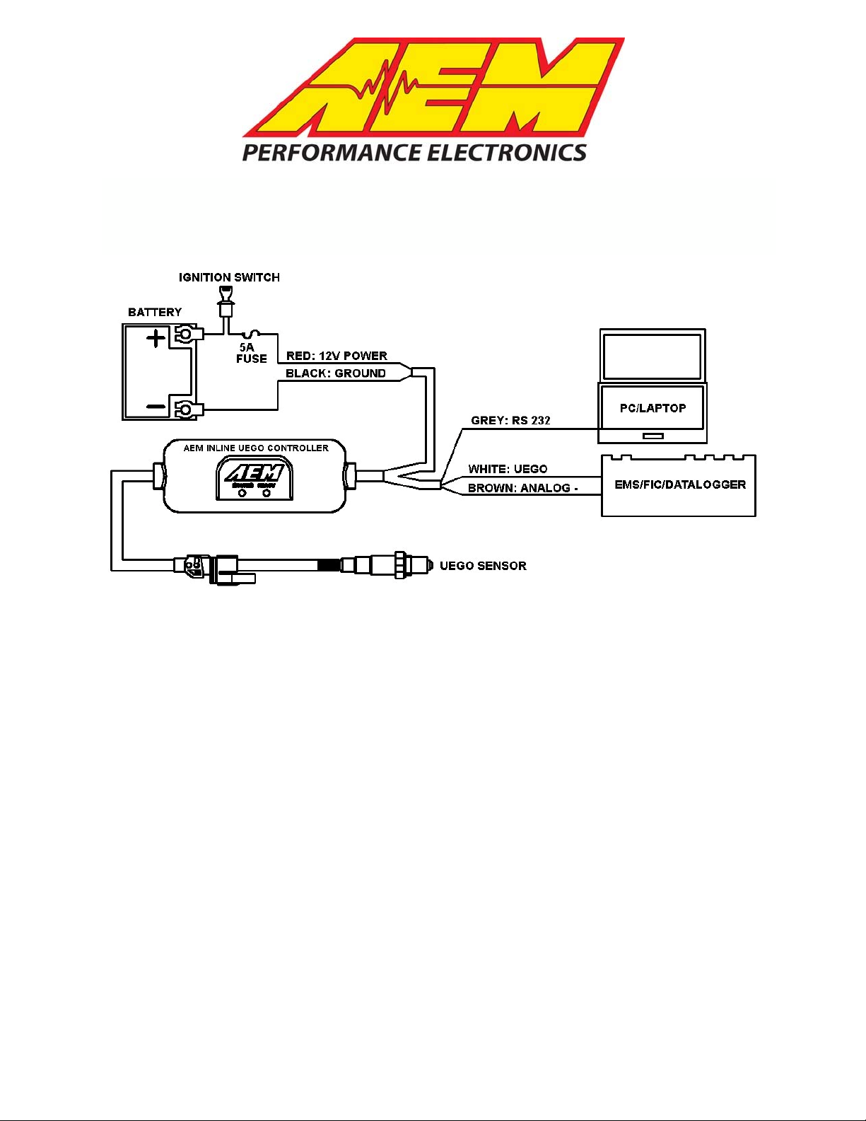
Figure 1. Wiring Schematic
Inline Wideband UEGO Controller Parts
1 x 30-2310 Inline Wideband UEGO Module
1 x 30-2001 UEGO Sensor
1 x 35-8535 Install Kit (UEGO Bung and 6 Butt Connectors)
1 x 10-2310 Installation Instructions
2 x Zip Tie
INSTALLATION
1. Disconnect the negative battery cable.
2. Find a suitable in-cab or under hood mounting location for the Inline UEGO
controller, away from any direct heat or water sources and shielded from the
elements. Secure the controller using the supplied zip ties as shown in Figure 3.
3. Connect the flying lead wires as shown in Figure 1.
4. Mount the UEGO sensor as shown in figure 2.
5. Plug the UEGO sensor connector on the UEGO controller into the mating
connector on the UEGO sensor.
AEM Performance
2205 126
th
Phone: (310) 484-2322 Fax: (310)
Street Unit A, Hawthorne, CA.
http://www
Instruction Part Number: 10-2310 Rev
© 2011 AEM Performance
.
Electronics
484-0152
aemelectronics.com
Electronics
90250
02
Page 2

RED - Connect to a switched, fused (5A) 12 volt power source.
BLACK – Connect to a clean power ground.
WHITE - Connect to Lambda + Input.
BROWN - Connect to sensor ground. Connect to power ground if sensor ground is not
available.
*GREY – Connect to RS232 serial port on laptop/pc. See section on Serial Data
Viewing
*optional – only needed for laptop/pc viewing of data.
UEGO Sensor Mounting
A weld-in UEGO bung is supplied for sensor installation. Mount the UEGO sensor in the
exhaust system at least 18 inches downstream from the exhaust port. If you anticipate
high EGT's (over 800C), run a turbocharger, run at high RPM for extended periods of
time or plan on running leaded race fuel then you must mount the sensor at least 36
inches or more downstream of the exhaust port as all of these can cause the sensor to
overheat. On turbocharged engines the UEGO sensor must be installed after the
turbo charger, if not, the pressure differential will greatly affect the accuracy of
the unit. For accurate readings, the sensor must be mounted before catalytic
converters and/or auxiliary air pumps. To prevent collection of liquids between the
sensor housing and sensor element during the cold start phase, the installation angle
should be inclined at least 10° from horizontal with the electrical connection upwards,
see Figure 2.
>10°
Figure 2. Minimum mounting angle for the UEGO Sensor
Controller Mounting
The UEGO controller provides for quick and easy mounting with the supplied zip ties.
See Figure 3 below.
Page 2
Page 3

ZIP TIES
Figure 3. Inline Wideband UEGO Controller Mounting
Indicator Lights
The Inline Wideband UEGO Controller has two indicator lights, see Figure 4. Both the
ready light and the status light flash during sensor warm up. Once the sensor reaches
operating temperature, usually within 30 seconds, the status light will turn off and the
ready light will remain on solid. During sensor warm up, AFR readings may not be
accurate. The status light will also flash if a sensor error is detected. The status light
will flash on and off a number of times, followed by a short pause. The error codes are
listed below in Table 1.
Status Indicator
Light
# of Flashes Fault Corrective Action
1-6 Sensor Wiring and/or sensor
7 System voltage below 10 volts dc
Figure 4. Indicator Lights
Table 1. Error Codes
Ready Indicator
Light
Check sensor cable for
broken wires/shorts
Check electrical system
for good connections
and proper function
Page 3
Page 4

UEGO Analog Output
The analog output from the Inline Wideband UEGO controller is a linear dc voltage
signal that varies from 0.5 Vdc at 8.5:1 AFR Gasoline (0.58 Lambda) to 4.5Vdc at
18.0:1 AFR Gasoline (1.22 Lambda) over the operating range of the controller. The
signal is used for sending information to a data logger or an engine management
system like the AEM EMS or F/IC. The transfer function for the output is listed below.
AFR = 2.375(V) + 7.3125
For example, if the output is 2.0 Vdc, the AFR is 12.06:1
2.375 * 2.0 + 7.3125 = 12.06
A table showing the analog output voltage and corresponding Air/Fuel ratios for some of
the common fuels is shown below in Table 2.
VOLTS LAMBDA AFR GAS
0.50 0.58 8.5 3.7 5.6 5.2
0.71 0.61 9.0 3.9 5.9 5.5
0.92 0.65 9.5 4.1 6.3 5.8
1.13 0.68 10.0 4.4 6.6 6.1
1.34 0.71 10.5 4.6 6.9 6.4
1.55 0.75 11.0 4.8 7.3 6.7
1.76 0.78 11.5 5.0 7.6 7.0
1.97 0.82 12.0 5.2 7.9 7.3
2.18 0.85 12.5 5.4 8.2 7.7
2.39 0.88 13.0 5.7 8.6 8.0
2.61 0.92 13.5 5.9 8.9 8.3
2.82 0.95 14.0 6.1 9.2 8.6
3.03 0.99 14.5 6.3 9.6 8.9
3.11 1.00 14.7 6.4 9.7 9.0
3.24 1.02 15.0 6.5 9.9 9.2
3.45 1.05 15.5 6.7 10.2 9.5
3.66 1.09 16.0 7.0 10.6 9.8
3.87 1.12 16.5 7.2 10.9 10.1
4.08 1.16 17.0 7.4 11.2 10.4
4.29 1.19 17.5 7.6 11.5 10.7
4.50 1.22 18.0 7.8 11.9 11.0
Table 2. AFR Values
AFR
METHANOL
Inline Wideband UEGO/AEM EMS Configuration
AFR E85
AFR
ETHANOL
With an EMS calibration open, go to Setup>Sensors>Oxygen Sensor #1(2)>O2 Sensor
#1(2) Cal Table>Table, and enter the values shown in Table 3 below into the O2 Sensor
#1(2) Cal Table.
Page 4
Page 5

Voltage AFR Voltage AFR Voltage AFR Voltage AFR
0.00 8.43 1.40 10.64 2.81 13.99 4.21 17.31
0.16 8.43 1.56 11.02 2.96 14.34 4.37 17.69
0.31 8.43 1.72 11.40 3.12 14.72 4.52 18.05
0.47 8.43 1.87 11.75 3.28 15.10 4.68 18.05
0.62 8.79 2.03 12.13 3.43 15.46 4.84 18.05
0.78 9.17 2.18 12.49 3.59 15.84 4.99 18.05
0.94 9.55 2.34 12.87 3.74 16.20 NA NA
1.09 9.90 2.50 13.25 3.90 16.58 NA NA
1.25 10.28 2.65 13.61 4.06 16.96 NA NA
Table 3. EMS Software Values
Connect the WHITE Analog Output + wire to the EMS Lambda input and the BROWN
Analog Output – wire to the EMS sensor ground. Table 4 below lists the Lambda and
Sensor ground pin locations for the different EMS part numbers.
AEM EMS P/N
30-1000/1001/1002/1040/1042 D14 D16 D21
30-1010/1012/1050/1052 C16 A23 C18
30-1020/1060 D7 D14 D12
30-1030/1031/1070 C13 C14 A16
30-1080 C16 C8 C14
30-1081 C16 B11 C14
30-1100/1101 B47 B48 B65
30-1110 1C 9C 13C
30-1120/1121/1130 B6 B14 B9
30-1220 30 31 60
30-1300 4 66 17
30-1310/1311/1312/1313 76 75 92
30-1320 71 73 34
30-1400 29 43 46
30-1401 44 43 46
30-1510 C2-31 C2-33 C2-32
30-1600/1601/1602/1603 19 NA 21
30-1610/1611/1612 46 52 50
30-1620/1621/1622/1623 29 55 30
30-1710 2N 4J 2C
30-1720 C3 D3 O3
30-1800 C3 A2 D4
30-1810 D19 B17 B19
30-1820/1821 A26 D25 C35
30-6100/30-6101 B47 B48 B65
30-6010/6012/6050/6052 C16 A23 C18
30-6000/6001/6002/6040/6042 D14 D16 D21
30-6060 D7 D14 D12
30-6310/30-6311/30-6313 76 75 92
30-6320 71 73 34
Table 4. EMS Pin Locations
Lambda
#1 Pin
Lambda
#2 Pin
Sensor
GND Pin
Page 5
Page 6

Inline Wideband UEGO/AEM F/IC Configuration
With an FIC calibration open, go to Setup>Aux Gauge, and complete the Aux gauge
setup window as shown below in Figure 5.
Figure 5. F/IC Aux Gauge Setup
Connect the WHITE Analog Output + wire to the Aux Gauge input and the BROWN
Analog Output – wire to the sensor ground. Table 5 below lists the Lambda and Sensor
ground pin locations for the different FIC part numbers.
AEM F/IC P/N Lambda Pin Sensor GND Pin
30-1910(X) Pin 18 of 22-pin connector Pin 5 of 22-pin connector
30-1930(X)
Pin 18 of 22-pin connector
Pin 20 of 20-pin connector
Table 5. F/IC Pin Locations
Pin 5 of 22-pin connector
Displaying Data with a PC/Laptop
Real time AFR data can also be viewed via a pc/laptop using an RS232 serial port
connection. Download the data viewer program and instructions from the AEM
Performance Electronics forum at www.aemelectronics.com
. . See figure 6.
Page 6
Page 7

Figure 6. PC Data Viewer
The grey wire from the UEGO Controller outputs the data stream in an RS232 serial
format. To connect to the pc/laptop, an RS-232 DB-9 connector is recommended. The
grey wire from the UEGO Controller goes to pin 2 of the RS-232 DB-9 connector. Pin 5
of the connector goes to ground. See Figure 7.
1 2 3 4 5
6 7 8
9
Figure 7. Wire View of RS-232 (DB-9) Male Plug
Connector Pinouts
The pinout for the UEGO sensor connector is shown below in Figure 8.
Figure 8. UEGO Connector Pinout
Page 7
Page 8

Specifications
UEGO Controller
Supply Current (nominal, peak) 1.3A, 2.7A peak
Differential Analog Outputs 1
Measuring Range: UEGO 8.5:1 to 18:1 AFR Gasoline, 0.58-1.22 Lambda
UEGO Sensor Accuracy 0.1 AFR
Operating Voltage (nominal) 8.5-15 volts dc
Harness & Connector Temp Limit:105C
Notes
If further tuning help is needed be sure to visit the video gallery or performance
electronics forum at www.aemelectronics.com for comprehensive instructional videos
and information.
The UEGO sensor contains a ceramic module and should not be subject to mechanical
or thermal shock or it may be damaged. The sensor is not designed for operation on
leaded fuels, doing so will dramatically shorten sensor life. Long term running in the rich
region (Lambda < 0.95) will shorten sensor life. High exhaust temperatures (over 850C)
will shorten sensor life. Engine oil consumption at a rate greater than 1 quart per 1,000
miles will shorten sensor life. With the UEGO Sensor installed, do not run the engine
without power applied to the X-WIFI.
Replacement/Optional UEGO Controller Components
30-2001 UEGO Sensor
35-4005 UEGO Sensor Bung
30-2003 No-Weld UEGO Sensor Install Kit
12 MONTH LIMITED WARRANTY
Advanced Engine Management Inc. warrants to the consumer that all AEM High Performance products will be free from defects in
material and workmanship for a period of twelve (12) months from date of the original purchase. Products that fail within this 12month warranty period will be repaired or replaced at AEM’s option, when determined by AEM that the product failed due to defects
in material or workmanship. This warranty is limited to the repair or replacement of the AEM part. In no event shall this warranty
exceed the original purchase price of the AEM part nor shall AEM be responsible for special, incidental or consequential damages
or cost incurred due to the failure of this product. The Bosch LSU 4.2 UEGO sensor has a limited life and is not warranted.
Warranty claims to AEM must be transportation prepaid and accompanied with dated proof of purchase. This warranty applies only
to the original purchaser of product and is non-transferable. All implied warranties shall be limited in duration to the said 12 month
warranty period. Improper use or installation, accident, abuse, unauthorized repairs or alterations voids this warranty. AEM disclaims
any liability for consequential damages due to breach of any written or implied warranty on all products manufactured by AEM.
Warranty returns will only be accepted by AEM when accompanied by a valid Return Goods Authorization (RGA) number. Product
must be received by AEM within 30 days of the date the RGA is issued.
Please note that before AEM can issue an RGA for any product, it is first necessary for the installer or end user to contact the AEM
Performance Electronics tech line at 1-800-423-0046 to discuss the problem. Most issues can be resolved over the phone. Under
no circumstances should a system be returned or a RGA requested before the above process transpires.
Need additional help? Contact the AEM Performance Electronics tech department at
1-800-423-0046 or tech@aempower.com, or visit the AEM Performance Electronics
forum at http://forum.aempower.com/forum/
Page 8
 Loading...