

Page 1
AEM Performance Electronics
2205 126th Street Unit A, Hawthorne, CA. 90250
Phone: (310) 484-2322 Fax: (310) 484-0152
http://www.aemelectronics.com
Instruction Part Number: 10-2320 Rev 01
2009 AEM Performance Electronics
Part Number 30-2320
AEM X-WIFI UEGO/EGT Module
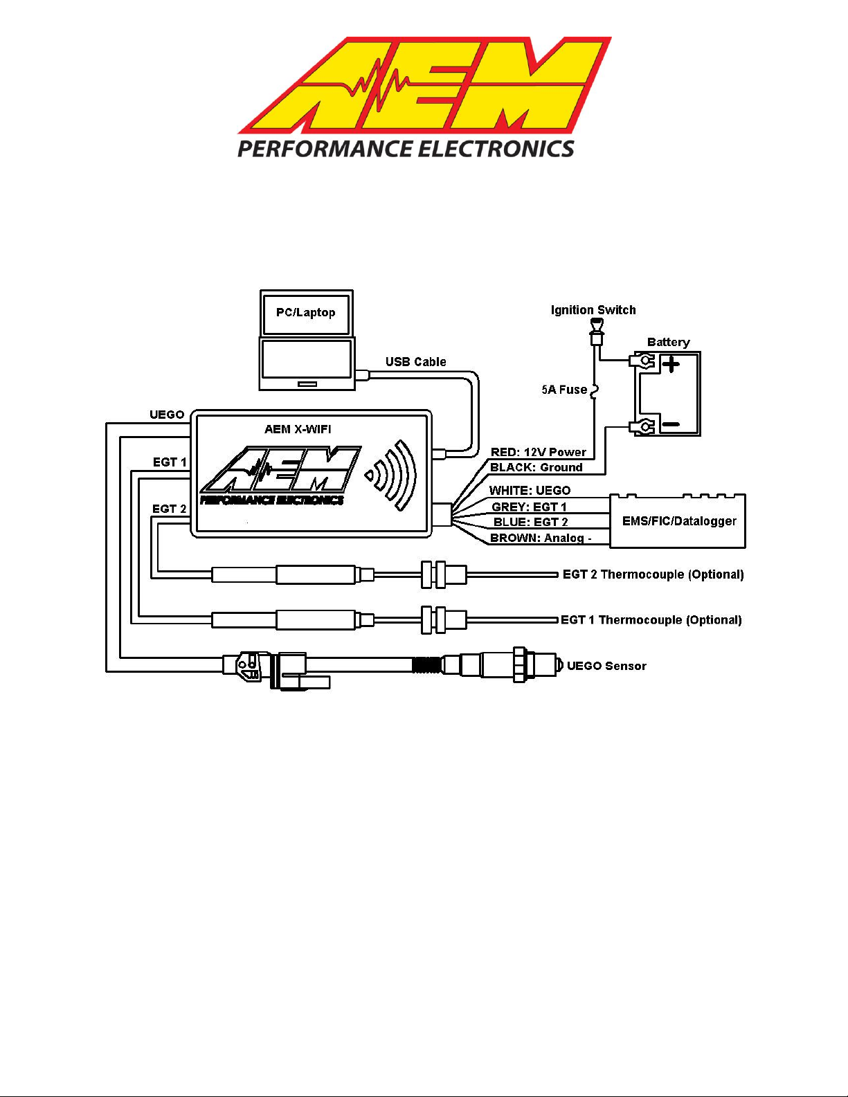
Figure 1. Wiring Schematic
AEM X-WIFI Parts
1 x 30-2320 X-WIFI Module
1 x 30-2001 UEGO Sensor
1 x 35-8535 Install Kit (UEGO Bung and 6 Butt Connectors)
1 x 10-2320 Installation Instructions
1 x 35-3416 8-Pin Power Harness
1 x 35-3400 6-Pin UEGO Sensor Harness
1 x 35-3009 USB Cable
4 x Zip Tie
Page 2

INSTALLATION
1. Disconnect the negative battery cable.
2. Find a suitable, in cab, mounting location and secure the X-WIFI module using
the supplied zip ties. Note: The X-WIFI is not weatherproof and should not be
mounted in the engine bay or exposed to outside elements
3. Plug the 8-pin power harness into the mating connector on the right side of the XWIFI and connect the wires as shown in Figure 1.
4. Mount the UEGO sensor as shown in figure 3.
5. Connect the sensor to the X-WIFI using the 6-wire sensor cable. The connector
with the grey latch connects to the sensor. The single-row connector connects to
the left side of the X-WIFI.
6. Mount the optional EGT sensor(s) as shown in Figure 6.
7. Slide the heat shrink tube over the sensor cable and connect the EGT to the
cable as shown below in Figure 7.
8. Connect the 3-pin EGT sensors cable(s) to the X-WIFI.
RED - Connect to a switched, fused (5A) 12 volt power source.
BLACK – Connect to a clean power ground.
*BLUE - Connect to available 5 volt analog channel for EGT input.
*GREY - Connect to available 5 volt analog channel for EGT input.
*WHITE - Connect to Lambda + Input.
*BROWN - Connect to sensor ground. (Must be connected if the White, Grey, or blue
wire is used)
*optional – only needed if using the available differential analog output
Wiring notes:
GREY – The GREY wire should be connected to an available analog channel on the
EMS or similar device.
BLUE – The BLUE wire should be connected to an available analog channel on the
EMS or similar device.
WHITE – The WHITE wire should be connected to the Lambda + input on the EMS or
the analog + input on a similar device.
BROWN – The BROWN wire should be connected to the Lambda – input or the analog
– input. If the EMS or similar device does not have a – input, the BROWN wire should
be connected to a sensor ground. If no sensor ground is available, the BROWN wire
should be connected to a power ground. Note: The BROWN wire must be connected
in order to get correct readings from the analog outputs.
Page 2
Page 3
Displaying Data with WIFI Enabled Electronic Devices
>10°
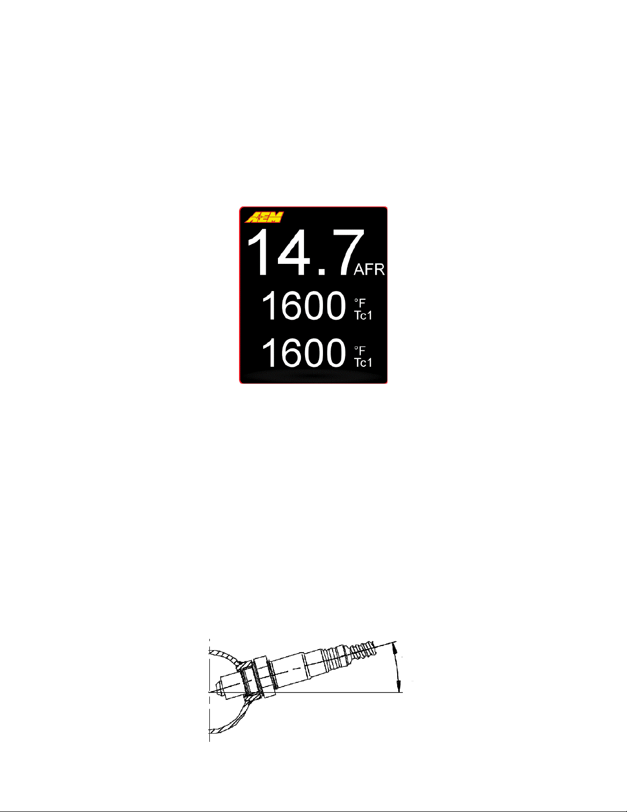
FIGURE 2. Web Page Data
Figure 3. Minimum mounting angle for the UEGO Sensor
Real time AFR and EGT data from the X-WIFI can be viewed on WIFI enabled
electronic devices using a standard web browser. Locate the network “AEM X-WIFI”
and connect. Type the address 192.168.3.88 in the address bar of the browser and
open the web page. A screen showing the AFR and EGT values will appear as shown
below in Figure 2. If a UEGO sensor error is detected, the AFR value will display “Err”
followed by a number. The number corresponds to the number of flashes on the error
status light as described in the Status Lights section below. Visit the video gallery at
www.aemelectronics.com for information on configuring specific WIFI enabled mobile
electronic devices.
UEGO Sensor Mounting
A weld-in M18 X 1.5 UEGO bung is supplied for sensor installation. Mount the UEGO
sensor in the exhaust system at least 18 inches downstream from the exhaust port. If
you anticipate high EGT's (over 800C), run a turbocharger, run at high RPM for
extended periods of time or plan on running leaded race fuel then you must mount the
sensor at least 36 inches or more downstream of the exhaust port as all of these can
cause the sensor to overheat. On turbocharged engines the UEGO sensor must be
installed after the turbo charger, if not, the pressure differential will greatly affect
the accuracy of the unit. For accurate readings, the sensor must be mounted before
catalytic converters and/or auxiliary air pumps. To prevent collection of liquids between
the sensor housing and sensor element during the cold start phase, the installation
angle should be inclined at least 10° from horizontal with the electrical connection
upwards, see Figure 3.
Page 3
Page 4
# of Flashes
Fault
Corrective Action
1-6
Sensor Wiring and/or sensor
Check sensor cable for
broken wires/shorts
7
System voltage below 10 volts dc
Check electrical system
for good connections
and proper function
Table 1. Error Codes
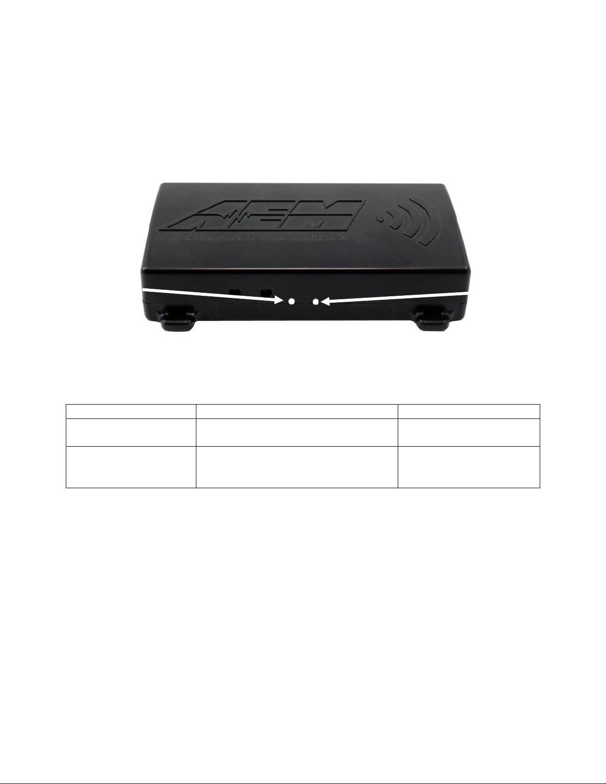
Figure 4. UEGO Status Lights
WARM UP
STATUS LIGHT
UEGO ERROR
STATUS LIGHT
Status Lights
The AEM X-WIFI has two status lights, see Figure 4. The warm up status light on the
left flashes during sensor warm up. Once the sensor reaches operating temperature,
usually within 30 seconds, the light will remain on. During sensor warm up, AFR
readings may not be accurate. The UEGO error status light on the right will flash if a
sensor error is detected. The status light will flash on and off a number of times,
followed by a short pause. The error codes are listed below in Table 1.
UEGO Analog Output
The UEGO analog output from the AEM X-WIFI is a linear dc voltage signal that varies
from 0.5 Vdc at 8.5:1 AFR Gasoline to 4.5Vdc at 18.0:1 AFR Gasoline over the
operating range of the X-WIFI. The signal is used for sending information to a data
logger or an engine management system like the AEM EMS or F/IC. The transfer
function for the output is listed below.
AFR = 2.375(V) + 7.3125
For example, if the output is 2.0 Vdc, the AFR is 12.06:1
2.375 * 2.0 + 7.3125 = 12.06
A table showing the analog output voltage and corresponding Air/Fuel ratios for some of
the common fuels is shown below in Table 2.
Page 4
Page 5

VOLTS
LAMBDA
AFR GAS
AFR
METHANOL
AFR E85
AFR
ETHANOL
0.50
0.58
8.5
3.7
5.6
5.2
0.71
0.61
9.0
3.9
5.9
5.5
0.92
0.65
9.5
4.1
6.3
5.8
1.13
0.68
10.0
4.4
6.6
6.1
1.34
0.71
10.5
4.6
6.9
6.4
1.55
0.75
11.0
4.8
7.3
6.7
1.76
0.78
11.5
5.0
7.6
7.0
1.97
0.82
12.0
5.2
7.9
7.3
2.18
0.85
12.5
5.4
8.2
7.7
2.39
0.88
13.0
5.7
8.6
8.0
2.61
0.92
13.5
5.9
8.9
8.3
2.82
0.95
14.0
6.1
9.2
8.6
3.03
0.99
14.5
6.3
9.6
8.9
3.11
1.00
14.7
6.4
9.7
9.0
3.24
1.02
15.0
6.5
9.9
9.2
3.45
1.05
15.5
6.7
10.2
9.5
3.66
1.09
16.0
7.0
10.6
9.8
3.87
1.12
16.5
7.2
10.9
10.1
4.08
1.16
17.0
7.4
11.2
10.4
4.29
1.19
17.5
7.6
11.5
10.7
4.50
1.22
18.0
7.8
11.9
11.0
Voltage
AFR
Voltage
AFR
Voltage
AFR
Voltage
AFR
0.00
8.43
1.40
10.64
2.81
13.99
4.21
17.31
0.16
8.43
1.56
11.02
2.96
14.34
4.37
17.69
0.31
8.43
1.72
11.40
3.12
14.72
4.52
18.05
0.47
8.43
1.87
11.75
3.28
15.10
4.68
18.05
0.62
8.79
2.03
12.13
3.43
15.46
4.84
18.05
0.78
9.17
2.18
12.49
3.59
15.84
4.99
18.05
0.94
9.55
2.34
12.87
3.74
16.20
NA
NA
1.09
9.90
2.50
13.25
3.90
16.58
NA
NA
1.25
10.28
2.65
13.61
4.06
16.96
NA
NA
Table 2. EMS Software Values
Table 2. AFR Values
Configuring the AEM EMS
With an EMS calibration open, go to Setup>Sensors>Oxygen Sensor #1(2)>O2 Sensor
#1(2) Cal Table>Table, and enter the values below into the O2 Sensor #1(2) Cal Table.
Connect the WHITE Analog Output + wire to the EMS Lambda input and the BROWN
Analog Output – wire to the EMS sensor ground. Table 3 below lists the Lambda and
Sensor ground pin locations for the different EMS part numbers.
Page 5
Page 6

AEM EMS P/N
Lambda
#1 Pin
Lambda
#2 Pin
Sensor
GND Pin
30-1000/1001/1002/1040/1042
D14
D16
D21
30-1010/1012/1050/1052
C16
A23
C18
30-1020/1060
D7
D14
D12
30-1030/1031/1070
C13
C14
A16
30-1080
C16
C8
C14
30-1081
C16
B11
C14
30-1100/1101
B47
B48
B65
30-1110
1C
9C
13C
30-1120/1121/1130
B6
B14
B9
30-1220
30
31
60
30-1300
4
66
17
30-1310/1311/1312/1313
76
75
92
30-1320
71
73
34
30-1400
29
43
46
30-1401
44
43
46
30-1510
C2-31
C2-33
C2-32
30-1600/1601/1602/1603
19
NA
21
30-1610/1611/1612
46
52
50
30-1620/1621/1622/1623
29
55
30
30-1710
2N
4J
2C
30-1720
C3
D3
O3
30-1800
C3
A2
D4
30-1810
D19
B17
B19
30-1820/1821
A26
D25
C35
30-6100/30-6101
B47
B48
B65
30-6010/6012/6050/6052
C16
A23
C18
30-6000/6001/6002/6040/6042
D14
D16
D21
30-6060
D7
D14
D12
30-6310/30-6311/30-6313
76
75
92
30-6320
71
73
34
Table 3. EMS Pin Locations
Configuring the AEM F/IC
With an FIC calibration open, go to Setup>Aux Gauge, and complete the Aux gauge
setup window as shown below in Figure 5.
Page 6
Page 7

AEM F/IC P/N
Lambda Pin
Sensor GND Pin
30-1910(X)
Pin 18 of 22-pin connector
Pin 5 of 22-pin connector
30-1930(X)
Pin 18 of 22-pin connector
Pin 20 of 20-pin connector
Pin 5 of 22-pin connector
Figure 5. F/IC Aux Gauge Setup
Table 4. F/IC Pin Locations
Connect the WHITE Analog Output + wire to the Aux Gauge input and the BROWN
Analog Output – wire to the sensor ground. Table 4 below lists the Lambda and Sensor
ground pin locations for the different FIC part numbers.
Thermocouple Mounting
The optional thermocouple comes with a stainless steel compression style mounting
adapter. The mounting adapter consists of three pieces: compression nut, ferrule
sleeve, threaded body. The threaded body has 1/8” NPT male threads. To install the
sensor, the threaded body can either be threaded into a hole with mating 1/8” NPT
threads, or welded to the pipe/manifold. Remove the compression nut, ferrule sleeve,
and thermocouple from the threaded body. For a welded installation, drill a 13/32” hole
and weld the threaded body, being careful not to cause any distortion. . For a threaded
installation, either thread the body into an existing hole with 1/8” NPT threads or drill a
hole using an “R” size drill bit and cut the threads using a 1/8” NPT tap. With the
compression nut and ferrule sleeve on the thermocouple, insert the thermocouple into
the threaded body so the tip of the thermocouple is near the center of the pipe/manifold
and tighten the compression nut to the threaded body. See Figure 6. Table 5 below
lists some of the common EGT measurements and corresponding thermocouple
mounting locations.
Page 7
Page 8

EGT Measurement
Mounting Location
Individual Cylinder EGT
1-2 inches from exhaust port
Turbine Inlet Temperature
2-3 inches from turbine inlet
Cylinder Bank EGT
Header collector
FERRULE SLEEVE
COMPRESSION NUT
THREADED BODY
PIPE/MANIFOLD
WITH 1/8” NPT
THREADS OR
13/32” HOLE
TIP OF THERMOCOUPLE
NEAR CENTER OF
PIPE/MANIFOLD
HEAT SHRINK
Figure 7. Thermocouple to Cable Connection
Figure 6. Thermocouple Mounting
Table 5. Common Thermocouple Mounting Locations
When using both thermocouples for comparison (bank 1 EGT and bank 2 EGT for
example), make sure to mount both thermocouples in a similar fashion (distance from
port, tip depth, tube diameter, etc) so the readings are not influenced by installation
differences.
Connecting the Thermocouple
Slide the supplied heat shrink onto the sensor cable. Connect the RED wire from the
thermocouple to the RED wire on the harness and the YELLOW wire from the
thermocouple to the YELLOW wire on the harness using the supplied 4-40 screws and
hex nuts. Make sure the connections are not touching. Center the heat shrink over the
connections and apply mild heat to the heat shrink until it shrinks over the connections.
See Figure 7.
EGT Analog Outputs
Page 8
Page 9

VOLTAGE
°F
°C
0.50
0
-18
0.75
113
45
1.00
225
107
1.25
338
170
1.50
450
232
1.75
563
295
2.00
675
357
2.25
788
420
2.50
900
482
2.75
1013
545
3.00
1125
607
3.25
1238
670
3.50
1350
732
3.75
1463
795
4.00
1575
857
4.25
1688
920
4.50
1800
982
Table 6. Analog EGT Calibrations
The analog EGT outputs from the AEM X-WIFI are linear dc voltage signals that vary
from 0.5 Vdc at 0 Degrees Fahrenheit (-18 Degrees Celsius) to 4.5Vdc at 1800
Degrees Fahrenheit (982 Degrees Celsius) over the operating range of the X-WIFI.
The signals are used for sending information to a data logger or an engine management
system like the AEM EMS or F/IC. The transfer functions for the analog outputs are
listed below in Degrees Fahrenheit and Degrees Celsius.
Temperature (Degrees Fahrenheit) = 450 * Voltage - 225
For example, if the output is 2.5 Vdc, the temperature is 900 Degrees Fahrenheit.
450 * 2.5 – 225 = 900 Degrees Fahrenheit
Temperature (Degrees Celsius) = 250 * Voltage – 143
For example, if the output is 2.5 Vdc, the temperature is 482 Degrees Celsius.
250 * 2.5 – 143 = 482 Degrees Celsius
A list of output voltages and corresponding temperatures is shown below in Table 6.
Configuration
The AEM X-WIFI has two configuration buttons. Configuration button one is used for
accessing the WIFI setup options. Configuration button two is used for future updates.
See Figure 8.
Page 9
Page 10

Figure 8. Configuration Buttons
CONFIGURATION
BUTTON 1
CONFIGURATION
BUTTON 2
WIFI
AEM X-WIFI is preconfigured for adhoc communications with standard WIFI settings
that are suitable for most applications. The IP address, subnet mask, and SSID are
listed below:
IP address: 192.168.3.88
Subnet Mask: 255.255.0.0
SSID: AEM X-WIFI
The default X-WIFI settings are permanently stored in the module and can be restored
by the following sequence. Plug the USB cable into the pc/laptop. Press and hold
configuration button 1. With configuration button 1 depressed, plug the USB cable into
the X-WIFI and continue to hold configuration button 1 for eight seconds then release.
The AEM X-WIFI is also capable of secure infrastructure WIFI communications. The
communication settings are configurable in the advanced configuration window. The
advanced configuration window can be viewed using a standard hyper terminal
communication. The settings for the hyper terminal communication are shown below in
Figure 9.
Page 10
Page 11

FIGURE 9. HYPER TERMINAL SETTINGS
FIGURE 10. ADVANCED WIFI CONFIGURATION
To view the advanced configuration screen, open the hyper terminal communication,
but do not connect. Plug the USB cable into the pc/laptop. Press and hold
configuration button 1. With configuration button 1 depressed, plug the USB cable into
the X-WIFI and continue to hold configuration button 1 for two seconds, then release.
Click the connect button on the hyper terminal communication. The advanced
configuration screen will appear as shown below in Figure 10.
Consult your router documentation for the necessary network settings.
Page 11
Page 12

Displaying Data with a PC/Laptop
Figure 12. Barrel Style Power Connection
POWER
CONNECTION
Figure 11. PC Data Viewer
Real time AFR and EGT data can also be viewed via a pc/laptop with USB connection.
See figure 11. Download the data viewer program and instructions from the AEM
Performance Electronics forum at www.aemelectronics.com.
Portable Power Connection
The AEM X-WIFI has an on-board barrel connector that can be used to power the
module using a 5 amp 12Vdc power supply when a hard wired power connection is not
desired. The power supply must have a 2.1MM ID X 5.5MM OD plug with the center pin
positive. See Figure 12.
Connector Pinouts
The pinouts for the 6-pin sensor harness, 3-pin sensor harness, and 8-pin power
harness are provided below in Figure 13.
Page 12
Page 13

X-WIFI
Supply Current (nominal, peak)
1.5A, 3A peak
Differential Analog Outputs
3
Measuring Range: UEGO
8.5:1 to 18:1 AFR Gasoline, 0.58-1.22 Lambda
UEGO Sensor Accuracy
0.1 AFR
Measuring Range: EGT
0 – 1800 Degrees Fahrenheit,
-18-982 Degrees Celsius
EGT Sensor Accuracy
0.75% FS
Operating Voltage (nominal)
8.5-15 volts dc
Harness & Connector Temp Limit:
105C
Web Browser Requirements
Javascript, Ajax, and Canvas for graphical web
pages
Figure 13. Harness Pinouts
Specifications
Notes
If further tuning help is needed be sure to visit the video gallery or performance
electronics forum at www.aemelectronics.com for comprehensive instructional videos
and information.
The UEGO sensor contains a ceramic module and should not be subject to mechanical
or thermal shock or it may be damaged. The sensor is not designed for operation on
leaded fuels, doing so will dramatically shorten sensor life. Long term running in the rich
region (Lambda < 0.95) will shorten sensor life. High exhaust temperatures (over 850C)
will shorten sensor life. Engine oil consumption at a rate greater than 1 quart per 1,000
miles will shorten sensor life. With the UEGO Sensor installed, do not run the engine
without power applied to the X-WIFI.
Replacement/Optional X-WIFI Components
30-2001 UEGO Sensor
35-4005 UEGO Sensor Bung
35-3416 8-Pin Power Harness
35-3400 6-Pin UEGO Sensor Harness
30-2065 K-Type Thermocouple with Bung (Optional)
35-2066 3-Pin Thermocouple Harness (Optional)
Page 13
Page 14

12 MONTH LIMITED WARRANTY
Advanced Engine Management Inc. warrants to the consumer that all AEM High Performance products will be free from defects in
material and workmanship for a period of twelve (12) months from date of the original purchase. Products that fail within this 12month warranty period will be repaired or replaced at AEM’s option, when determined by AEM that the product failed due to defects
in material or workmanship. This warranty is limited to the repair or replacement of the AEM part. In no event shall this warranty
exceed the original purchase price of the AEM part nor shall AEM be responsible for special, incidental or consequential damages
or cost incurred due to the failure of this product. The Bosch LSU 4.2 UEGO sensor has a limited life and is not warranted.
Warranty claims to AEM must be transportation prepaid and accompanied with dated proof of purchase. This warranty applies only
to the original purchaser of product and is non-transferable. All implied warranties shall be limited in duration to the said 12 month
warranty period. Improper use or installation, accident, abuse, unauthorized repairs or alterations voids this warranty. AEM disclaims
any liability for consequential damages due to breach of any written or implied warranty on all products manufactured by AEM.
Warranty returns will only be accepted by AEM when accompanied by a valid Return Goods Authorization (RGA) number. Product
must be received by AEM within 30 days of the date the RGA is issued.
Please note that before AEM can issue an RGA for any product, it is first necessary for the installer or end user to contact the AEM
Performance Electronics tech line at 1-800-423-0046 to discuss the problem. Most issues can be resolved over the phone. Under
no circumstances should a system be returned or a RGA requested before the above process transpires.
Need additional help? Contact the AEM Performance Electronics tech department at
1-800-423-0046 or tech@aempower.com, or visit the AEM Performance Electronics
forum at http://forum.aempower.com/forum/
Page 14
 Loading...