

Page 1
AEM Performance Electronics
2205 126th Street Unit A, Hawthorne, CA. 90250
Phone: (310) 484-2322 Fax: (310) 484-0152
http://www.aemelectronics.com
Instruction Part Number: 10-2320 Rev 01
2009 AEM Performance Electronics
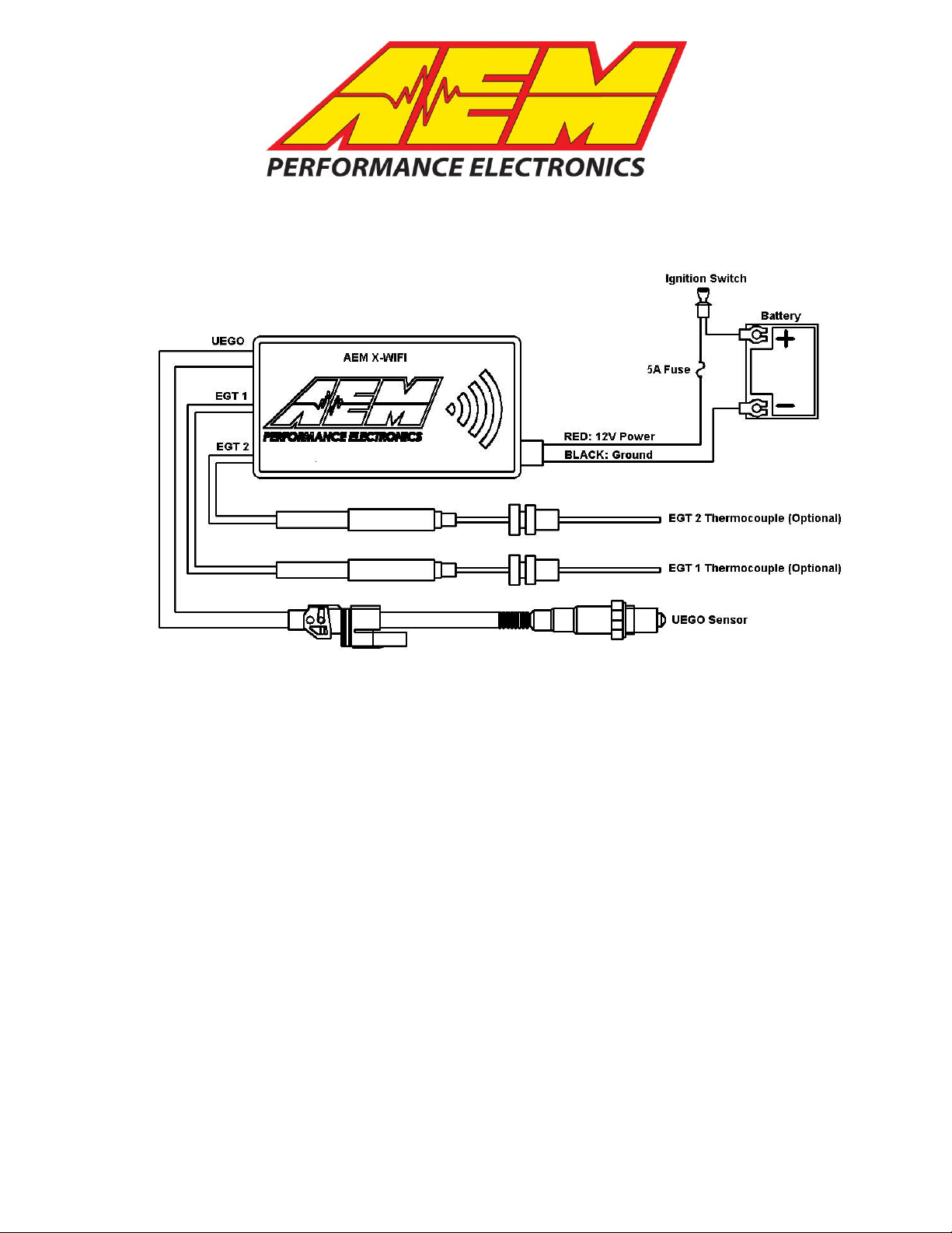
AEM X-WIFI EGT Connection Guide
Figure 1. Wiring Schematic
INSTALLATION
1. Disconnect the negative battery cable.
2. Using the supplied Stainless Steel 1/8”NPT compression mount, mount the EGT
thermocouple as shown in Figure 2. Common locations for mounting the EGT
thermocouple are 1-2 inches from the exhaust port, 2-3 inches before the turbine
inlet, or in the header collector.
3. Connect the EGT thermocouple to the extension harness as shown in Figure 3.
4. Connect the 3-pin connector on the thermocouple extension harness to either the
EGT 1 location or EGT 2 location as shown above in Figure 1.
When using both thermocouples for comparison (bank 1 EGT and bank 2 EGT for
example), make sure to mount both thermocouples in a similar fashion (distance from
port, tip depth, tube diameter, etc) so the readings are not influenced by installation
differences.
Page 2
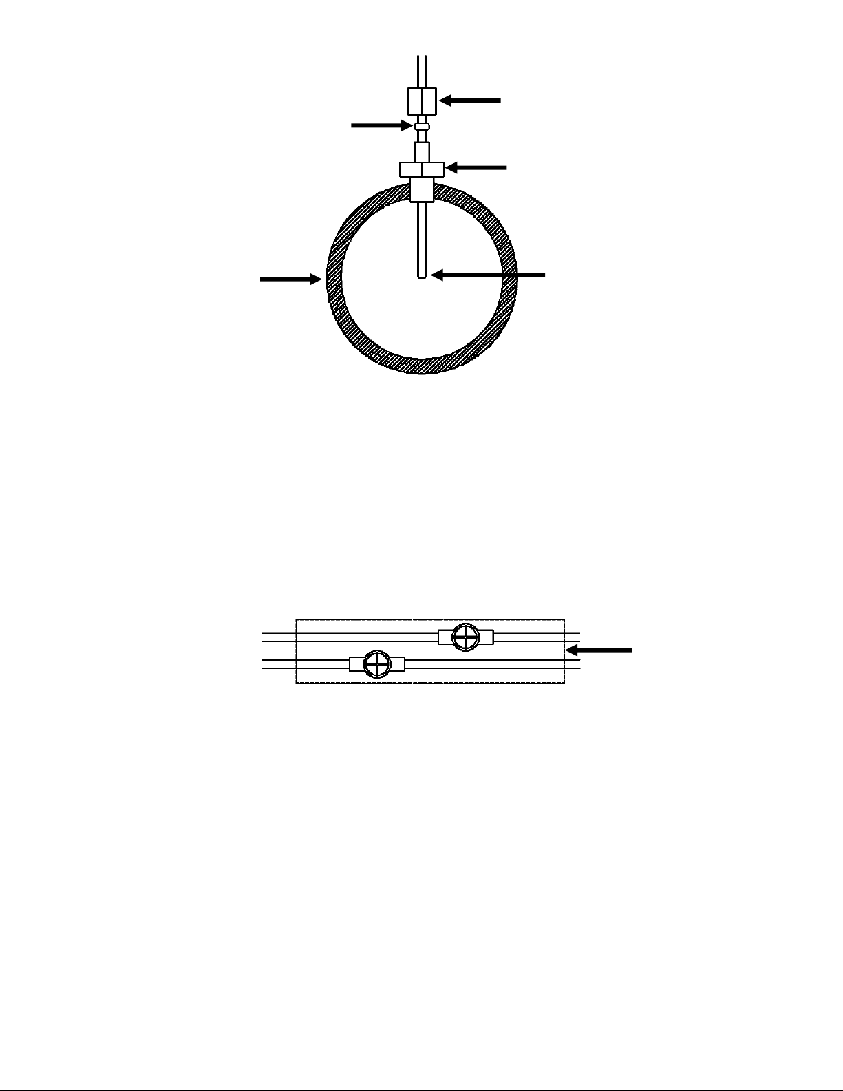
FERRULE SLEEVE
COMPRESSION NUT
THREADED BODY
PIPE/MANIFOLD
WITH 1/8” NPT
THREADS OR
13/32” HOLE
TIP OF THERMOCOUPLE
NEAR CENTER OF
PIPE/MANIFOLD
Figure 2. Thermocouple Mounting
HEAT SHRINK
Figure 3. Thermocouple to Cable Connection
Connecting the Thermocouple
Slide the supplied heat shrink onto the sensor cable. Connect the RED wire from the
thermocouple to the RED wire on the harness and the YELLOW wire from the
thermocouple to the YELLOW wire on the harness using the supplied 4-40 screws and
hex nuts. Make sure the connections are not touching. Center the heat shrink over the
connections and apply mild heat to the heat shrink until it shrinks over the connections.
See Figure 7.
Notes
If further tuning help is needed be sure to visit the video gallery or performance
electronics forum at www.aemelectronics.com for comprehensive instructional videos
and information.
A more detailed version of the instruction manual is available for download at
www.aemelectronics.com.
Page 2
 Loading...