

Page 1
WARNING:
The installation of this Fuel Rail Kit requires the removal and installation of fuel system
components. Improper assembly/installation may result in bodily injury or property
damage. If you are not qualified to perform this installation, please refer the installation
to a professional. Read and understand these instructions before attempting to install
this product.
FUEL
RAIL
AN ADAPTER KIT
Installation Instructions for part number:
25-391
1989-1999 Mitsubishi Eclipse Turbo 4G63
Fuel Rail AN Adapter Kit
ADVANCED ENGINE MANAGEMENT INC.
2205 126TH Street, Unit A Hawthorne, CA. 90250
Phone: (310) 484-2322 Fax: (310) 484-0152
Http://www.aempower.com
Part Number: 10-381
2002 Advanced Engine Management, Inc.
Page 2
! WARNING
Read and understand these instructions BEFORE attempting to install this product.
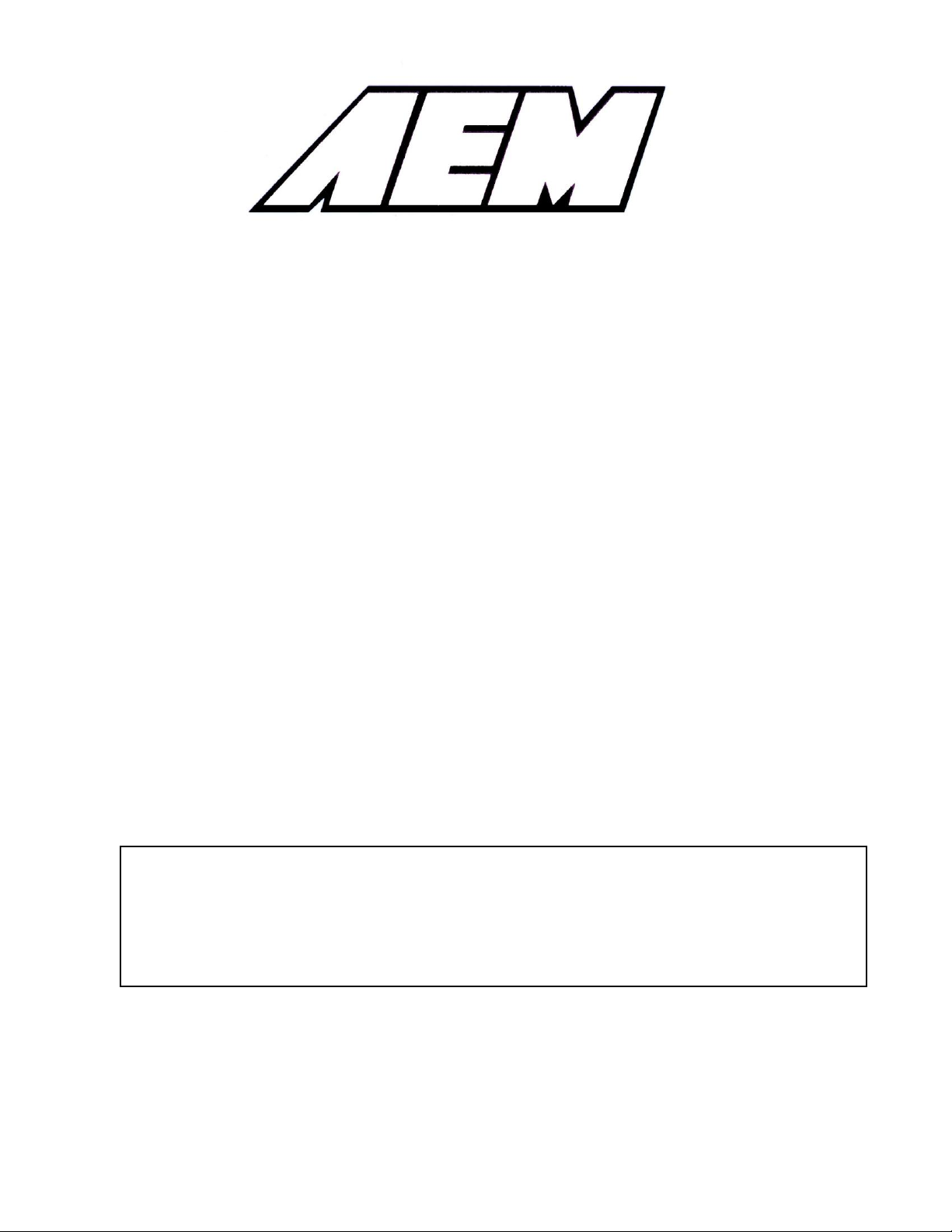
Dowel
pins
a) Remove the two flathead screws from the
bottom of the fuel rail.
b) Remove the dowel pins from the holes
exposed by the removal of the screws. It may
be necessary to push them through from the
access holes in the top of the rail using a paper
clip.
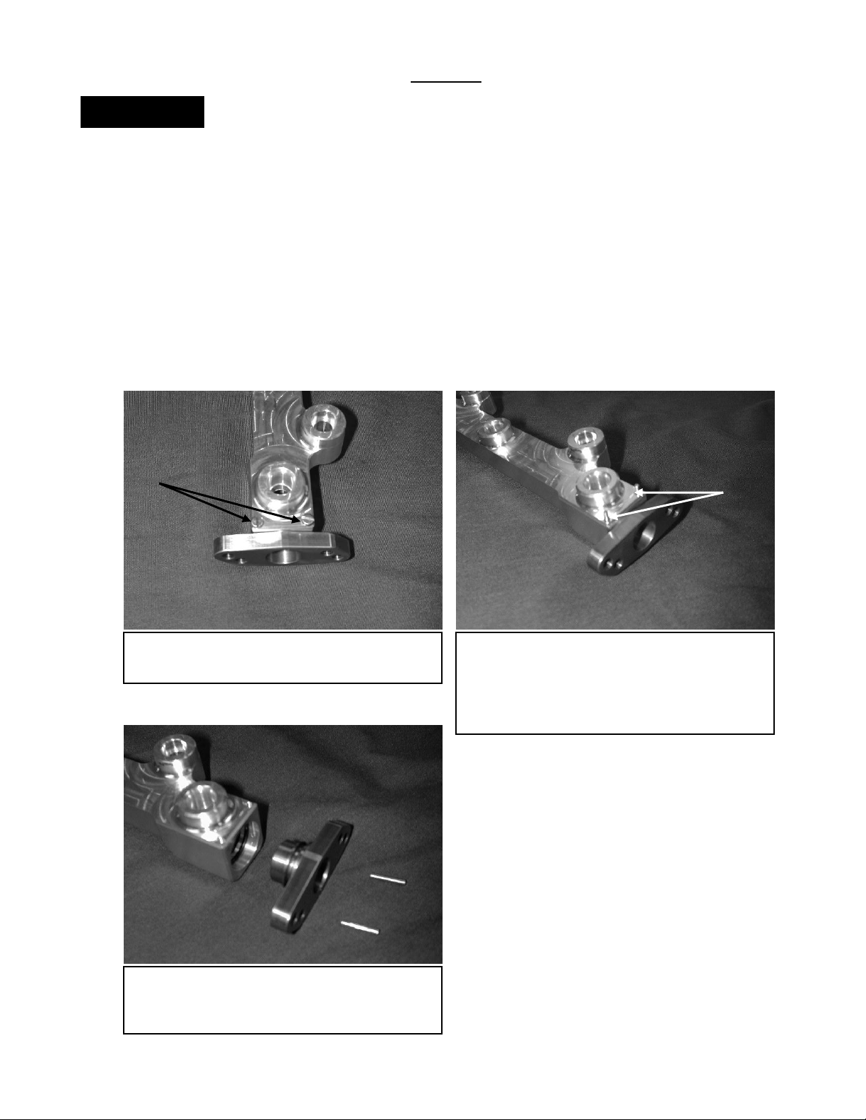
c) Pull the end adapter out of the fuel rail.
Remove the old o-rings and thoroughly clean
all surfaces.
Remove
Do not smoke while working on the fuel system.
Keep open flames or sparks away from your work area.
Be sure to relieve fuel pressure before working on fuel system.
1) Getting started
a) Make sure vehicle is parked on a level surface.
b) Set parking brake.
c) If engine has run within the past two hours let it cool down.
d) Clean area around the fuel rail so that dirt cannot get into the engine.
Note it is recommended to:
Replace all cushion rings, seal rings and fuel injector insulators when fuel rail is disassembled.
2) Disassembly of the AEM Fuel Rail
Page 3

3) Assembly of the AEM Fuel Rail
a) Make sure both ends of the fuel rail are
clean and free of debris and burrs.
b) Insert one 1-3024 o-ring into the inner
groove. Make sure the o-ring is evenly seated
in the groove.
c) Insert another 1-3024 o-ring up against the
first shoulder. Make sure the o-ring is seated
evenly against the shoulder and is past the
slots for the dowel pins.
Make sure o-ring is
past these slots.
d) Refer to this cut-away view for proper o-
ring installation. Warning: The o-rings MUST
be properly seated as shown in this
diagram. Improper installation may
damage the o-rings and cause leakage.
First o-ring goes
in this groove
Second o-ring goes
against this
O-rings MUST be past
the dowel pin slot
Warning: Improper assembly of the AEM fuel rail may result in leakage. Be sure to pressure test the
fuel rail on the vehicle before starting the engine or test-driving. If there is any sign of leakage, the
problem must be corrected before proceeding.
Page 4

f) Gently insert the end adaptor into the fuel
rail. Make sure the o-rings stay in place and
are not torn. Insert two 1-2061 dowel pins into
the dowel pin holes.
g) Insert and tighten two 1-2062 screws into
the dowel pin holes. Repeat steps b-g for the
other side of the fuel rail.
e) Lightly lubricate the tip of the end adapter
and the o-rings in the end of the fuel rail. Clean
engine oil works well.
AEM –AN
Adapter
Supplied –6
Crush Washer or
Earl’s Stat-O-Seal
(P/N 178009ERL)
Earl’s –6 to 9/16-18
Adapter (P/N 985006ERL)
Earl’s –6 90 Degree
Auto-Fit Hose End
This configuration works well on the inlet side of the fuel rail only. A line needs to be made from the
fuel filter to the fuel rail. Because this configuration extends off of the fuel rail so far, it is not
suitable for the return side of the fuel rail. The hose end will come into contact with the timing belt
cover if this configuration is used on the return side of the fuel rail.
Lubricate
Dowell Pins
4) Plumbing the AEM Fuel Rail
The AEM AN Adapter Kit is intended for use in custom fuel system applications. The AEM Universal
Fuel Pressure Regulator (P/N 25-302) may be mounted in a remote location and plumbed into the
fuel system using this kit. Shown below are suggested methods for attaching AN style lines to the
AEM Fuel Rail. Final fuel system configuration and plumbing is up to the end user.
Page 5

Qty.
Part Number
Description
2
2-645
Mitsubishi AN Adapter
4
1-3024
O-Ring (BUNA 70)
2
1-3007
Crush Washer, -6
1
10-381
Instructions
For Technical Inquiries
Please E-Mail us at
tech@aempower.com
This configuration works well on either the inlet or return side of the fuel rail. A line needs to be
constructed from the filter to the rail on the inlet side of the fuel rail. On the return side of the fuel rail,
a line needs to be made from the rail to the remote mounted regulator (AEM P/N 25-302), and from
the regulator’s outlet port to the vehicle’s fuel return line.
AEM –AN
Adapter
Supplied –6
Crush Washer or
Earl’s Stat-O-Seal
(P/N 178009ERL)
Earl’s –6 Swivel Seal Hose
End (P/N 849006ERL)
5) Finishing Touches
a) Connect the negative battery terminal.
b) Turn the ignition switch to the on position for approximately two seconds. Do not operate the starter.
Then turn the ignition switch to the off position.
c) Repeat this procedure three times, and then check all components that were removed during installation
for any signs of fuel leakage.
i. Be sure to check the area around the fuel inlet fitting, the injectors, the regulator,
and the 1/8” NPT plug. If these items were not installed correctly, they may be
prone to leakage.
d) If there are signs of leakage you MUST correct the leak before proceeding.
e) If there are no signs of leakage, then start engine and again check for leaks. If there is any sign of
leaking you MUST repair the leak before driving the vehicle.
Bill of Materials for Kit # 25-391
 Loading...