

Page 1

GD Midea Refrigeration Equipment Co. Ltd
MULTI SPLIT TYPE, HEAT PUMP AIR CONDITIONERS
Technical service manual 2005
R407C multi Series
Indoor Models
[A SERIES] [B SERIES]
EL-KFR26G/TN2Y-A EL-KFR26G/TN2Y-B
EL-KFR36G/TN2Y-A EL-KFR36G/TN2Y-B
Outdoor Models
M2OA-18HRN2 M2OA-21HRN2
M3OA-27HRN2 M3OA-30HRN2
Multi SERIES
Page 1 of 33
Page 2

1. Features
2. Specification
3. Dimensions
4. Refrigeration cycle diagram
5. Operation limits
6. Wiring diagram
7. Troubleshooting
8. Electronic function
9. Exploded view parts
10. Characteristic of temp. sensor
Page 2 of 33
Page 3

1.Features
1.1 Compact design
1.2 High efficiency and quiet operation
1.3 Unitary outdoor unit design
Page 3 of 33
Page 4
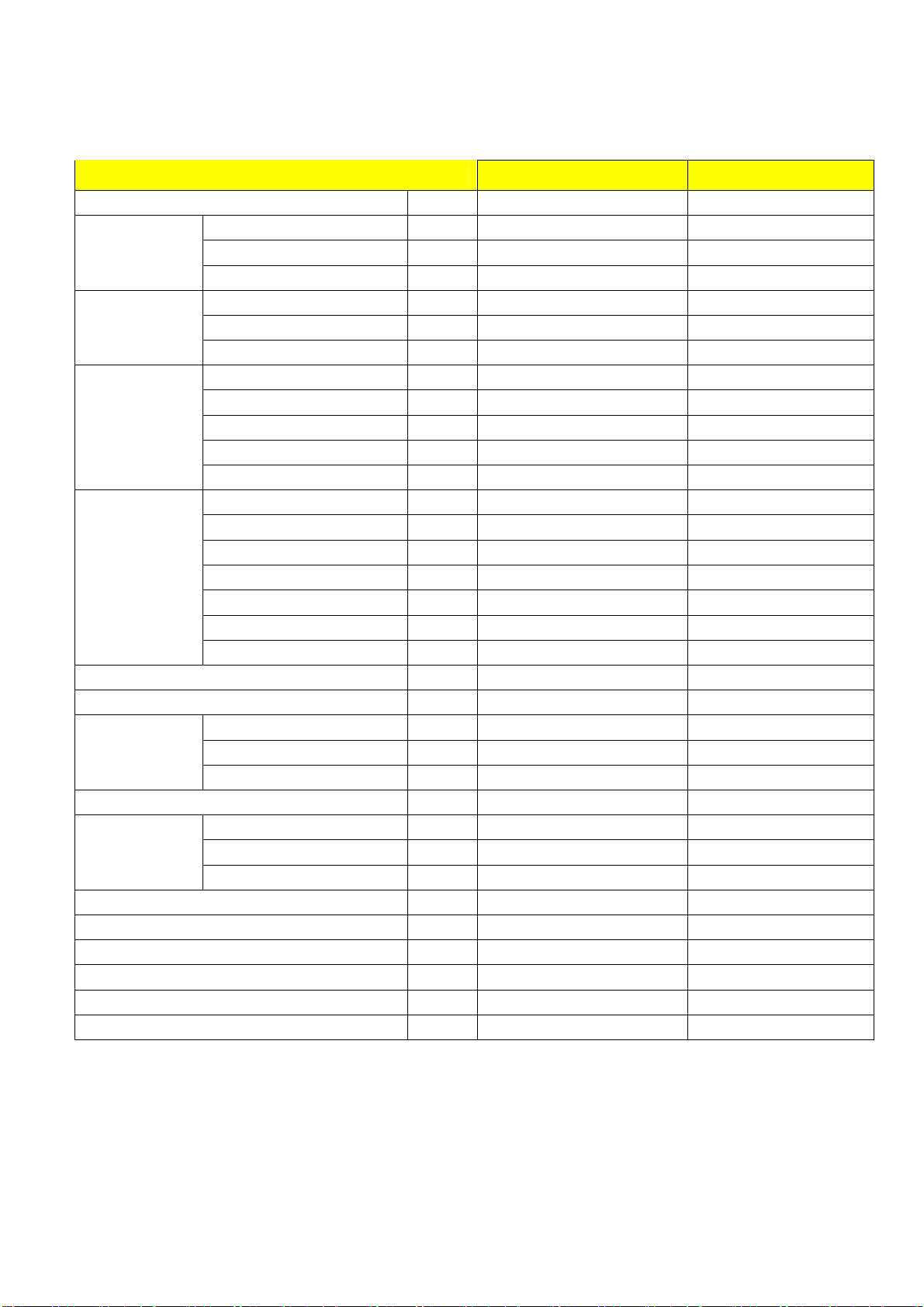
2 Specification
2.1 Indoor unit
Model EL-KFR26G/TN2Y-A(B) EL-KFR36G/TN2Y-A(B)
Power supply Ph-V-Hz 1, 220-240V~,50Hz 1, 220-240V~,50Hz
Capacity Btu/h 9000 12000
Cooling
Heating
Indoor fan motor
Indoor coil
Indoor air flow (Hi/Mi/Lo) m3/h 500/460/410 680/520/420
Indoor noise level (Hi/Mi/Lo) dB(A) 40.5/37.4/34.6 42.0/35.0/30.0
Indoor unit
Design pressure(Hi/Lo) MPa 2.8/1.2 2.8/1.2
Refrigerant piping
Connection wiring No No
Plug type 10A 16A
Thermostat type Electronic control Electronic control
Operation temp
Ambient temp
Application area m2 14-21 18-26
Input W 36.5 51.5
Rated current A 0.17 0.24
Capacity Btu/h 10000 13000
Input W 36.5 51.5
Rated current A 0.17 0.24
Model RPG13H RPG20D
Brand Welling WELLING
Input W 36.5 51.5
Capacitor uF 1.2 1.5
Speed(hi/mi/lo) r/min 1180/1080/1000 1250/1000/800
a.Number of rows 2 2
b.Tube pitch(a)x row pitch(b) mm 21x13.37 21×13.37
c.Fin spacing mm 1.3 1.3
d.Fin type (code) Hydrophilic aluminium Hydr0philiC aluminium
e.Tube outside dia.and type mm
f.Coil length x height x width mm 578X252X26.74 635×315×27.34
g.Number of circuits 2 2
Dimension (W*H*D) mm 750×250×214(210) 815x282x217
Packing (W*H*D) mm 837X340X295 915x360x295
Net/Gross weight Kg 9/11 10.5kg/12kg
Liquid side/ Gas side mm
Max. refrigerant pipe length m 10 10
Max. difference in level m 5 5
φ7 INNEGROOVE TUBE φ7, innergroove tube
Ф6.35/Ф9.53 Ф6.35/Ф12.7
℃
℃
17-30 17-30
18-45 18-45
Page 4 of 33
Page 5
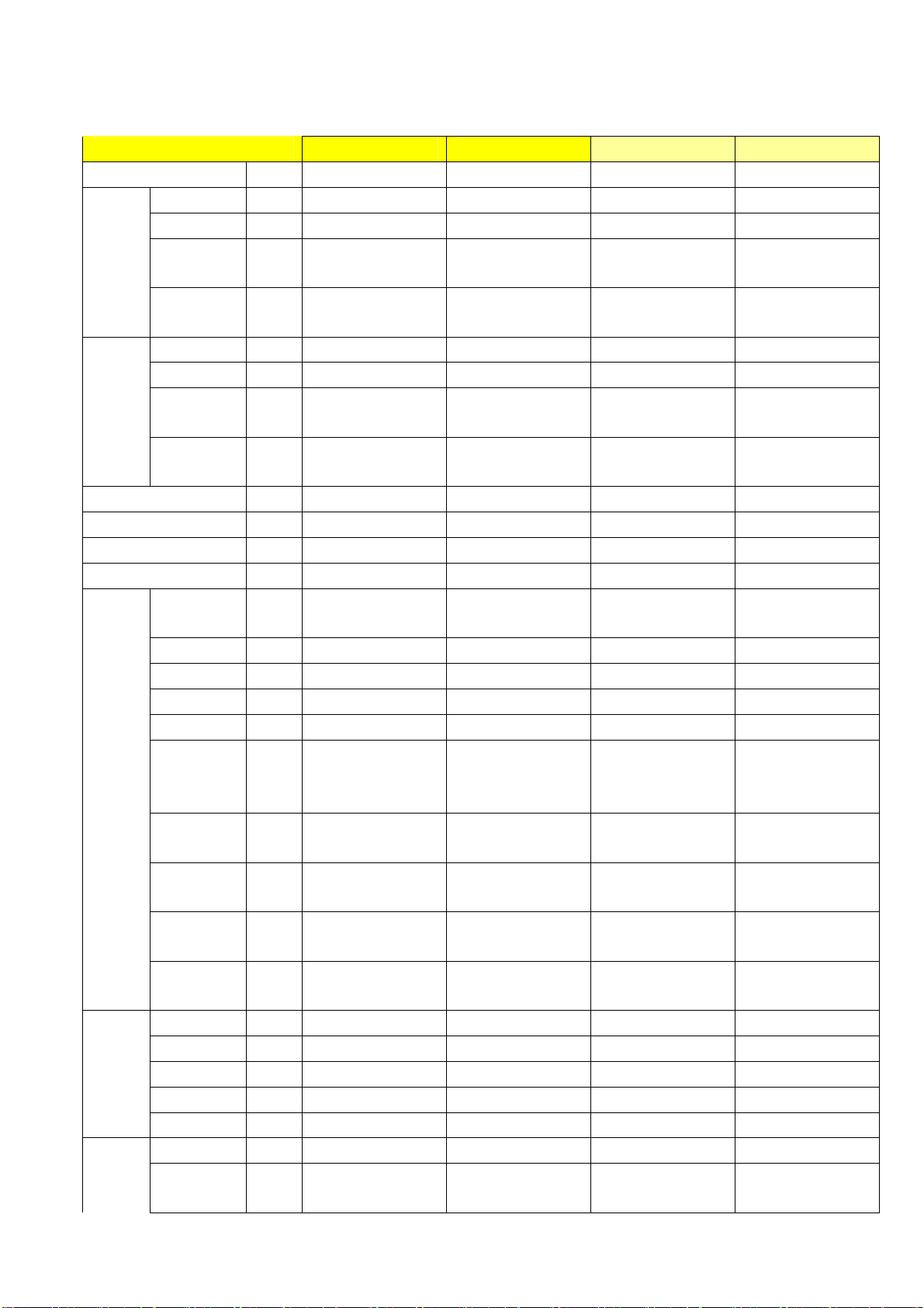
2.2 Outdoor unit
Model M2OA-18HRN2 M2OA-21HRN2 M3OA-27HRN2 M3OA-30HRN2
Power supply
Capacity Btu/h 9000X2 9000+12000 9000x3 9000x2+12000
Input W 1050X2 960+1100 1050X3 1800+1300
Cooling
Rated
current
EER
Capacity Btu/h 10600X2 10000+13000 10600x3 13000+20000
Input W 1080X2 960+1140 1080X3 1750+1300
Heating
Rated
current
COP
Moisture Removal L/h 1.0x2 1.0+1.2 1.0x3 1.0x2 +1.2
Max. input consumption W 1330X2 1500+1900 1330X3 2200+1800
Max. current A 6.0X2 7.0+8.0 10.0 +8.2 10.0 +8.2
Starting current A 19.8 19.8+30 40+30 40+30
Model PG180X1C-4DZ3X2
Type ROTARY Rotary Rotary Rotary
Brand GD TOSHIBA GD TOSHIBA GD Toshiba GD Toshiba
Capacity Btu/h 10800X2 10800+13650 18080; 13650 18080; 13650
Input W 1000X2 1000+1310 1760; 1310 1760; 1310
Rated
Compre
ssor
current(RLA
)
Locked rotor
Amp(LRA)
Thermal
protector
Capacitor uF 25X2 25+35
Refrigerant
oil
Model
Outdoor
fan
motor
Brand WeiLing WeiLing Welling Welling
Input W 154 154 107Wx2 107Wx2
Capacitor uF
Speed r/min
Outdoor
coil
a.Number of rows
b.Tube pitch(a)x
row pitch(b)
Ph-V-Hz
1Ph,220-240V,50Hz 1Ph,220-240V,50Hz 1Ph,220-240V,50Hz 1Ph,220-240V,50Hz
A 4.6X2 5+6 4.6X3 8.2+5.8
Btu/w
.h
8.6 8.8 8.5, 8.9, 8.5,
A 4.8X2 5+6 4.8X3 8.2+5.8
Btu/w
.h
9.8 9.6
PG180X1C-4DZ3+P
G225X2C-4FT
PG295X2CS-4KU1;
PG225X2C-4FT
9.6 10.2/ 9.6
PG295X2CS-4KU1;
PG225X2C-4FT
A 4.4X2 4.4+6.1 8.5; 6.1 8.5; 6.1
A 24X2 24+31 44, 31 44, 31
UP3QE0591-T61X2
UP3QE0591-T61+U
P3RE0591-T56
Internal Internal
35uF/440VAC;
35uF/440VAC
35uF/440VAC;
35uF/440VAC
ml 400X2 400+ 480 750; 480 750; 480
YDK50-4G1 YDK50-4G1
4uFx2 4uFx2
1150 1150
2 2
25.4x22 25.4x22
mm
YDK69-6 YDK69-6
4 4
900/670 900/670
2 2
25.4X22 25.4X22
Page 5 of 33
Page 6
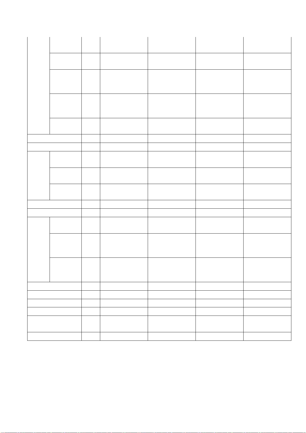
c.Fin
spacing
d.Fin type
(code)
e.Tube
outside
dia.and type
f.Coil length
x height x
width
g.Number of
circuits
Outdoor air flow m3/h
Outdoor noise level dB(A)
Dimension(
W*H*D)
Outdoor
unit
Refrigerant type g R407C/800X2 R407C/750+1000 R407C/ 1470+820 R407C/ 1470+820
Design pressure(Hi/Lo) MPa 2.8/1.2 2.8/1.2 2.6 2.6
Refriger
ant
piping
Connection wiring No No No No
Plug type No NO No No
Thermostat type Electronic control Electronic control Electronic control Electronic control
Operation temp
Ambient temp
Application area m2 (14-21)x2 14-21; 18-26 (14-21)x3 (14-21)x2,16-24
Packing
(W*H*D)
Net/Gross
weight
Liquid side/
Gas side
Max.
refrigerant
pipe length
Max.
difference in
level
mm
mm
mm
mm
mm
Kg
mm(in
ch)
m 10 10 10 (each unit) 10 (each unit)
m 5 5 5 (each unit) 5 (each unit)
℃
℃
1.7 1.7
HYDROPHILIC
ALUMINIUM
Ф9.53
INNERGROOVE
TUBE
810X610X44 810X610X44
12 12
1900 2070
58 58 60 62
895X345X655 895X345X655
1050X470X720 1050X470X720
73/77 60/65 90/94 90/94
Ф6.35/Ф9.53
17-30 17-30 17~30 17~30
18~45(cooling);
-7~30(heating)
HYDROPHILIC
ALUMINIUM
Ф9.53
INNERGROOVE
TUBE
Ф6.35/Ф9.53; Ф
6.35/Ф12.7
18~45(cooling);
-7~30(heating)
Ф9.53, Innergroove
1.5 1.5
Hydrophilic
aluminium
tube
813X812X44 813X812X44
5(A System);4(B
System)
1450x2 1450x2
860X830X330 860X830X330
983X915X425 983X915X425
Ф6.35/Ф9.53;Ф
6.35/Ф12.7
18~45(cooling);
-7~30(heating)
Hydrophilic
aluminium
Ф9.53, Innergroove
tube
5(A System);4(B
System)
Ф6.35/Ф9.53
18~45(cooling);
-7~30(heating)
Page 6 of 33
Page 7
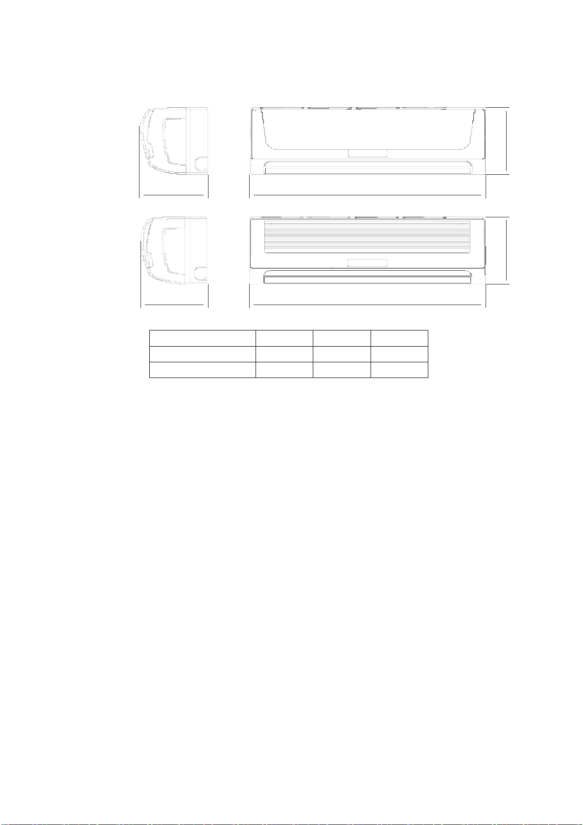
3.Dimensions
3.1 Indoor unit
Pan el A
Pan el B
C
D B
C
A B
A B C
EL-KFR26G/TN2Y-A(B)
EL-KFR36G/TN2Y-A(B)
214 750 250
217 815 282
Page 7 of 33
Page 8
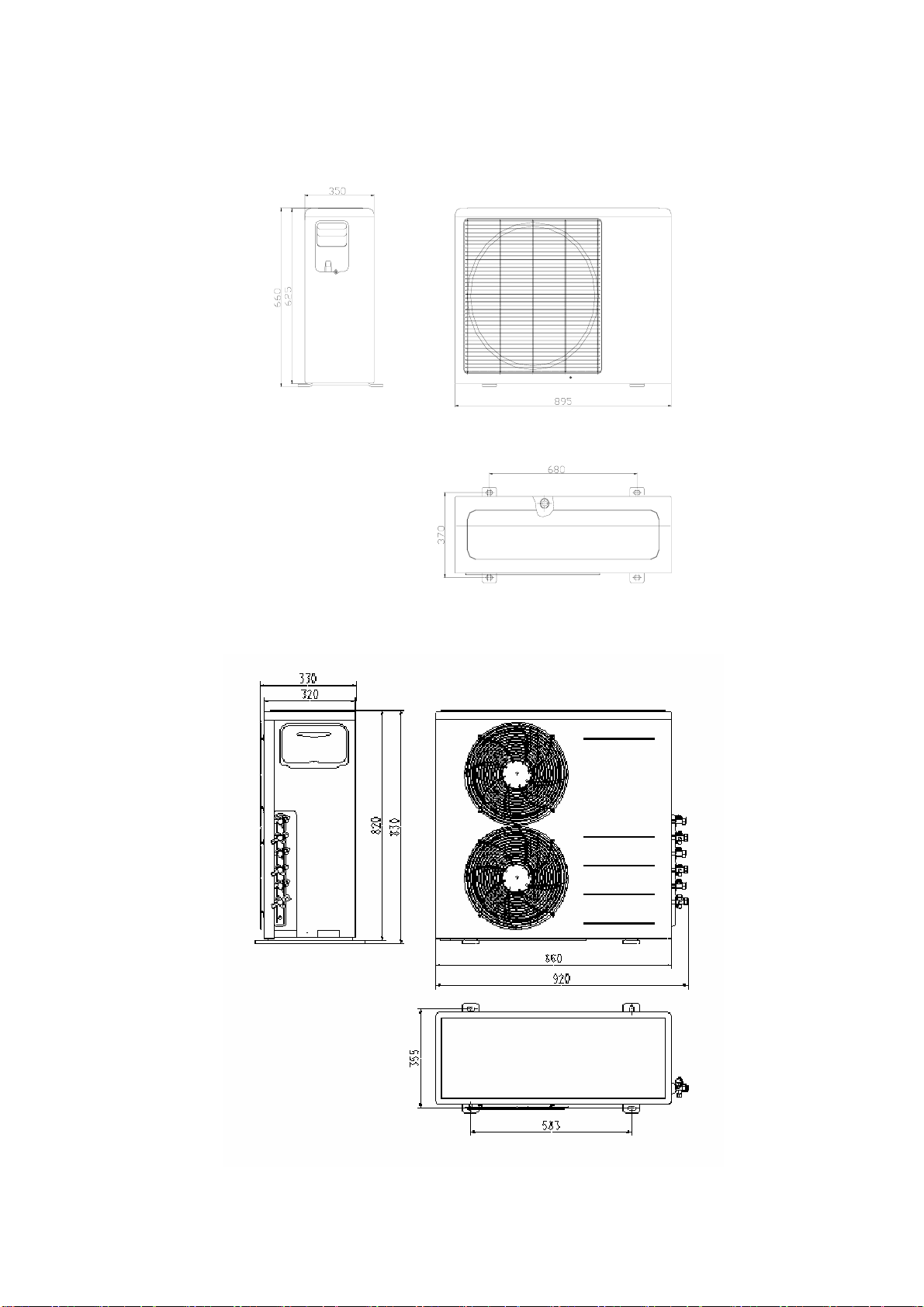
3.2 Outdoor unit
Outdoor unit 18K/21K
Outdoor unit 27K/30K
Page 8 of 33
Page 9
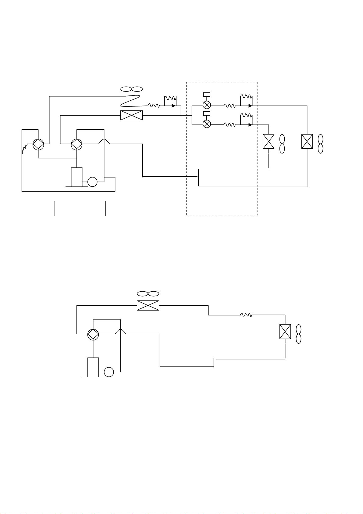
4.Refrigeration cycle diagram
“1 drive 3 system” is made up of one “1 drive 1 system” and one “1 drive 2 system”.
SV2
SV1
PMV1
PMV2
2#
1# T2
T1
Compressor
refrigeration distributor
1 drive 2 system
SV1:Primary four-way valve SV2:Secondary four-way valve PMV1,PMV2:Electronic expansive valve
T1,T2:Indoor pipe temperature sensor
Condenser
Four-way valve
Evaporator
Compressor
1 drive 1 system
Notice:For 1 drives 2 system, there are two individual refrigerant circuit and two compressors, but for the 1drive 2
system in the 1 drive three system, there is only one refrigerant circuit and only one compressor.
Page 9 of 33
Page 10
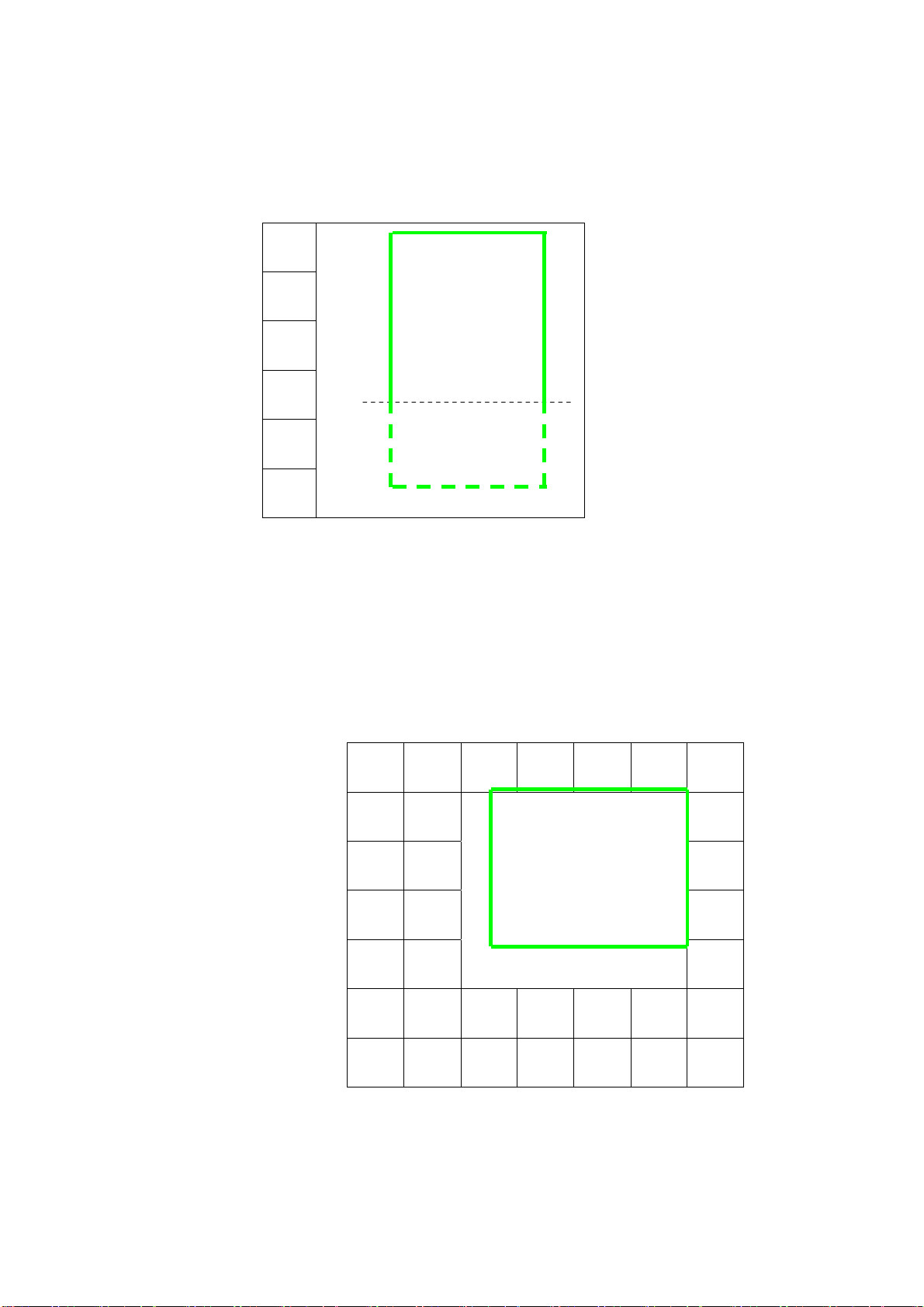
5.Operation limits
5.1Cooling operation
Outdoor unit air temp.℃ DB
45
17
-7
Indoor air temp.
Note: 1.The chart is the result from the continuous operation under constant air temperature
Condition. However, excludes the initial pull-down stage.
2.The operation range below the dashed is the result added the low ambient kit.
5.2Heating operation
COOLING
0 17 32
℃ DB
Indoor air temp. ℃ DB
30
25
20
15
10
5
Note : The chart is the result from the continuous operation under constant air
temperature conditions. However, excludes the initial pull-down stage.
-5 5 15 25
Outdoor unit air temp.
℃ DB
Page 10 of 33
Page 11

6.Wiring diagram
Indoor unit
A&B indoor unit
Page 11 of 33
Page 12
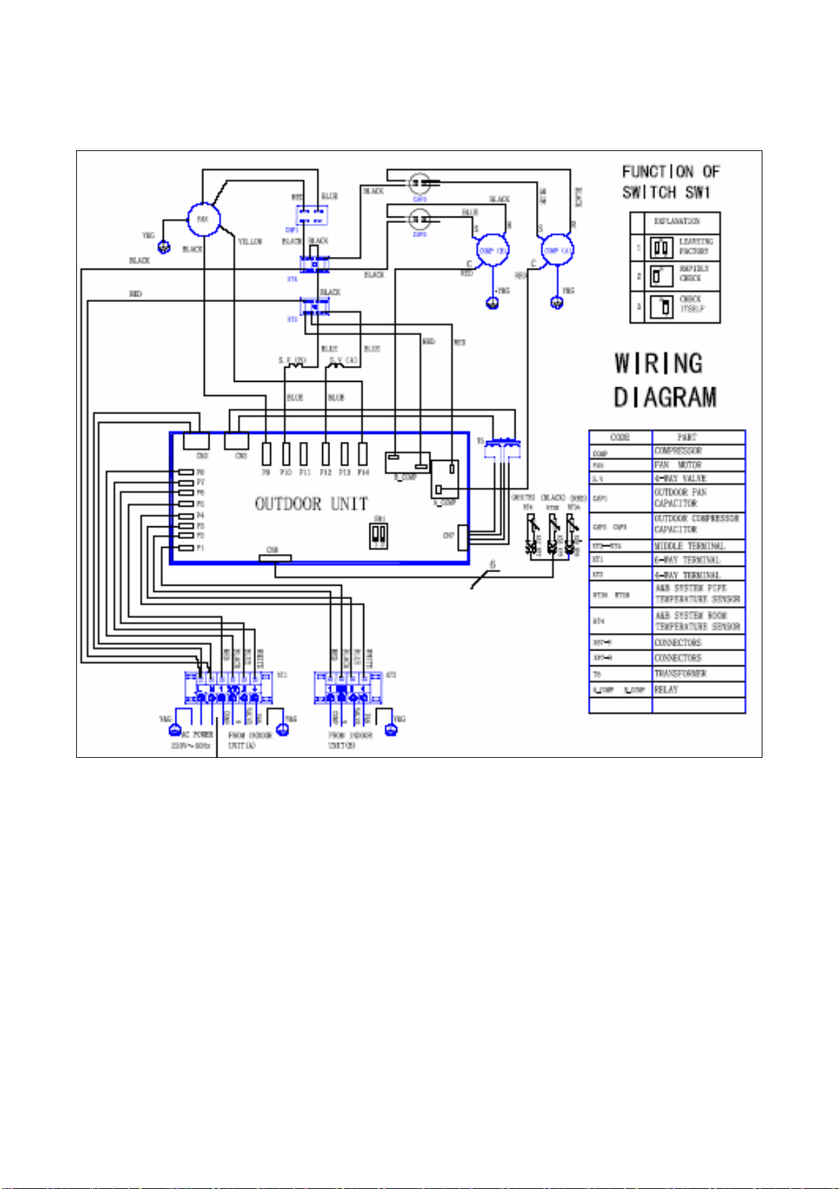
Outdoor unit
For 1 drive 2 outdoor unit
Page 12 of 33
Page 13

For 1 drive 3 outdoor unit
Page 13 of 33
Page 14

7.Troubleshooting
7.1 Indoor unit
7.1.1 Troubleshooting for indoor unit
Operation
lamp
Timer
lamp
Failure phenomenon
☆ X
☆
On
On Indoor room temp. or evaporator sensor is open circuit or short circuit
☆
☆ ☆
r Extinguish
☆ Flash at 5Hz
Indoor fan speed has been out of control for over 1 minute
EEROM error
No over-zero signal
Failure phenomenon Operation lamp Timer lamp
Indoor fan speed has been out of control for over 1 minute ☆ X
Is connector connection good?
No Yes
Is voltage being applied to the fan motor?
Repair the connector
Yes No
Fan motor is defective
Indoor PCB is defective
Failure phenomenon Operation lamp Timer lamp
Indoor room temp. or evaporator sensor is open circuit or short circuit ☆ On
Is connection to connector good?
Yes
Replace the sensor
No
Repair connector
Page 14 of 33
Page 15

Failure phenomenon Operation lamp Timer lamp
Over current protection of the compressor occurs 4 times X ☆
Operation lamp off and Timer lamp flashes
No Yes
After changing the main control board, check if the failure releases.
The voltage of power supply is too low (less than 187V)?
Yes
Indoor PCB is defective
Yes No
Power supply fault Outdoor unit fault (such as the compressor)
Failure phenomenon Operation lamp Timer lamp
EEROM error On ☆
EEROM error, indoor PCB is defective.
Failure phenomenon Operation lamp Timer lamp
No over-zero signal ☆ ☆
This is alarm signal when the main chip can’t detect over-zero signal. When such failure occurs, the main
control board must have fault.
7.2 Outdoor unit
Failure phenomenon LED1 LED2 LED3
Stand by
High temp. protect of condenser
Temp. sensor in condenser 1 is open circuit or short circuit
Temp. sensor in condenser 2 is open circuit or short circuit
☆ ☆ ☆
☆ ☆
☆
☆
☆ Flash at 2Hz
Page 15 of 33
Page 16

8 Electronic functions
8.1 Electric Control working environment
8.1.1 Input voltage: 145~260V
8.1.2 Input power frequency: 50Hz/60Hz
8.1.3 Ambient temperature: -7°C~+43°C
8.1.4 Indoor fan normal working amp is less than 1A,
8.1.5 Outdoors fan. Normal working amp is less than 1A
8.1.6 Four-way valve normal working amp is less than 0.5A.
8.1.7 Swing motor: DC12V.
8.2 Proper symbols and their meanings
TA: Indoor ambient temperature
TE: Indoor evaporator temperature
TS: Setting temperature through the remote controller
TE1: Anti-cold wind, from Fan Off to Breeze temperature
TE2: Anti-cold wind, from Breeze to Setting Fan Speed temperature
TE3: Anti-cold wind, from Setting Fan Speed to Breeze temperature
TE4: Anti-cold wind, from Breeze to Fan Off temperature
TE5: Evaporator low temperature protection entering temperature
TE6: Evaporator low temperature protection restoring temperature
TE7: Evaporator high temperature protection, compressor off temperature
TE8: Evaporator high temperature protection, fan off temperature
TE9: Evaporator high temperature protection, restoring temperature
T3: Outdoor unit pipe sensor
T4: Outdoor temperature sensor
8.3 Systematic functions.
Remote receiving.
Testing and forced run.
Position set for indoor unit wind vane.
LED displaying and alarm.
On or off Timer.
Protection for the compressor.
High temperature protection of indoor heat exchanger in heating mode.
Auto defrosting and heating recovery under heating mode.
Anti cold air under heating mode.
Anti frozen under cooling mode.
Page 16 of 33
Page 17

8.5 Protection
8.5.1 The compressor functions protection with a delay of three minutes.
8.5.2 High temp. protection of condenser.
8.5.3 Sensor protection at open circuit and breaking disconnection
8.5.4 Temperature Fuse break protection
8.5.5 Fan Speed is out of control. When Indoor Fan Speed is too high(higher than High
Fan+300RPM)or too low(lower than 400RPM), the entire unit stops and LED displays
failure information and can’t returns to normal operation automatically.
8.6 Fan-only mode
Fan speed is high/mid/low/ Auto
8.7 Cooling mode
The 4-way valve is closed under cooling mode.
The action of the compressor and the outdoor fan:
Condition Compressor Outdoor fan
TA> Ts+1 On On Temp. up
TA<Ts+1 Off Off
TA> Ts On On Tem p . do w n
TA<Ts Off Off
TA: Indoor ambient temperature
TS: Setting temperature through the remote controller
Auto fan under cooling mode:
Condition
T=Indoor Temp.-Setting Temp.
Temp. up
Tem p . do w n
T<3℃ Low
3℃<T<5℃ Mid.
T>5℃ High
T> 3℃ High
1℃<T<3℃ Mid.
T<1℃ Low
Indoor fan speed
Anti-freezing control to indoor evaporator under cooling mode
Condition
Temp. Time
T> TE6 On On Temp. up
T< TE6 >5 Minutes Off Off
T> TE5 On On Tem p . do w n
T< TE5 >5 Minutes Off Off
Compressor Outdoor fan
Condenser high-temperature protection under heating mode
T3 >65℃, turn off compressor.
TE5: Evaporator low temperature protection entering temperature
TE6: Evaporator low temperature protection restoring temperature
8.8 Dehumidifying mode
8.8.1 The 4-way valve is off in dehumidifying mode
8.8.2 Compressor and Indoor Fan actions in dehumidifying mode
Compressor run 5 minutes , and indoor fan run 5 minutes in low speed, then turn off the
Page 17 of 33
Page 18

compressor, indoor fan run 5 minutes in low speed. And repeat on and off cycle.
8.8.3 Low room temperature protection:
When room temperature decreases to below 10℃, the compressor and the outdoor fan
will stop(indoor fan is Breeze). Dehumidifying operation will be resumed when room
temperature restores to over 13℃.
8.8.4 Under dehumidifying mode, the anti-freezing function of the indoor heat exchanger is the
same as that of cooling mode.
8.9 Heating mode
8.9.1 Generally, the 4-way valve is open in heating mode, but it is closed in defrosting mode.
4-way valve must delay 2 minutes compared with compressor if the compressor changed
into non-heating mode or turned off. 4-way valve doesn't delay in dehumidifying mode.
8.9.2 Generally, the outdoor fan is turned off with the on-off action of compressor in heating
mode, except for the defrosting mode or the end of defrost.
8.9.3 Action conditions of compressor under heating mode: compressor must run for 7
minutes after starting and then judge temperature. Meanwhile other protections are still
valid.
Condition Compressor Outdoor fan
TA> Ts+3 Off Off Room temp. up
TA<Ts+3 On On
TA< Ts+2 On On Room temp. down
TA>Ts+2 Off Off
TA: Indoor ambient temperature
TS: Setting temperature through the remote controller
8.9.4 Indoor Fan actions under heating mode
Indoor Fan can be set at HIGH/MID/LOW/AUTO by using a remote controller, but
Anti-cold wind function has the priority.
Anti-cold wind control function under heating mode
Condition
TE
Indoor exchanger temp. up
Indoor exchanger temp. down
TE<TE1 Off
TE1<TE<TE2 Breeze
TE>TE2 Setting fan speed
TE> TE3 Setting fan speed
TE3<TE<TE4 Breeze
TE<TE4 Off
Indoor fan speed
TE: Indoor evaporator temperature
TE1: Anti-cold wind, from Fan Off to Breeze temperature
TE2: Anti-cold wind, from Breeze to Setting Fan Speed temperature
TE3: Anti-cold wind, from Setting Fan Speed to Breeze temperature
TE4: Anti-cold wind, from Breeze to Fan Off temperature
Page 18 of 33
Page 19

8.9.5 Auto wind under heating mode
Condition
T=Indoor Temp.-Setting Temp.
T<2℃ High Room temp. up
T>2℃ Mid.
T> 0℃ Mid. Room temp. down
T<0℃ High
Indoor fan speed
8.9.6 Indoor evaporator high-temperature protection under heating mode
Condition Compressor Outdoor fan
Indoor exchanger temp. up
TE<TE8 On On
TE8<TE<TE7 On Off
TE>TE7 Off Off
TE>TE9 Off Off Indoor exchanger temp. down
TE<TE9 On On
TE: Indoor evaporator temperature
TE7: Evaporator high temperature protection, compressor off temperature
TE8: Evaporator high temperature protection, fan off temperature
TE9: Evaporator high temperature protection, restoring temperature
8.10 Defrosting operation (Available for heating only).
8.10.1 Defrosting condition:
When T3<0℃ and compressor runs 40 minutes.
T3: Temp. of condenser.
8.10.2 Ending condition of defrost
If one of following conditions is satisfied, end the defrost and turn into heating:
A.The defrost time has reached to 10 minutes.
B.T3>20. ℃
8.10.3 Time sequence of the whole defrosting procedure is as follows
Compressor
ON
ON
4-way Valve
OFF
Outdoor Fan
ON
OFF
Page 19 of 33
Page 20

8.11 Automatic operation mode
8.11.1 The air conditioner automatically selects one of the following operation modes: cooling,
heating or ventilation according to the difference between room temp. (TA) and set temp.
(TS).
TA—TS Operation mode
TA— TS>2 ℃ Cooling
-1 ≤TA℃ —TS≤+2℃ Fan-only
TA— TS<- 1℃ Heating (Fan-only for cooling only type)
8.11.2 The indoor fan blows automatically in corresponding selected mode.
8.11.3 The motion of indoor fan’s vane should accord with the selected operation mode.
8.11.4 One mode should be carried out for at least 15 minutes once selected. If the compressor
cannot start for 15 minutes, reselect the operation mode according to the room temp.
and set temp.or reselect when the set temp. varies.
8.12 Forced cooling function
8.12.1 Select forced cooling function with the forced cooling button or the switch.
8.12.2 The compressor is unconditionally turned on, after 30 minutes cooling operation whose
fan mode is set as low, the A/C operates under the DRY mode with a set temp. of 24℃.
8.12.3 All protections of remote control cooling are available under forced cooling operation.
8.13 Forced Auto function
Select forced auto function with the forced auto button or the switch in the display
board.
In forced auto status the A/C operates under remote control mode with a set temp. of
24℃.
8.14 Timer Function Requirement
The maximum length of timer is 24 hours and the minimum resolving power is 15
minutes.
8.15 Economic Running
8.15.1 The economic running function is available under cooling, heating or auto mode.
8.15.2 Cooling:
The set temperature rise 1℃ per hour. Two hours later, the set temperature will
maintain as a constant and the air circulation is kept at low speed.
8.15.3 Heating:
The set temperature decrease 1℃ per hour. Two hours later, the set temperature will
maintain as a constant and the air circulation is kept at low speed (Cold air proof
function takes precedence over all).
8.15.4 Auto:
The economic running function operates in accordance with the selected running mode
by the auto mode.
Page 20 of 33
Page 21

8.16 Outdoor fan motor
T4: Outdoor temp.
T4 Outdoor fan motor
T4>27℃ High speed Cooling mode
T4<25℃ Low speed
T4>13℃ Low speed Heating mode
T4<11℃ High speed
Page 21 of 33
Page 22

9 Exploded view parts
9.1 INDOOR UNIT
Exploded View Parts for Model: EL-KFR26G/TN2Y-A(B) 220-240V~ 50Hz :Indoor Unit
No. Part Name Quantity BOM code No. Part Name Quantity BOM code
1 Front panel (type B) 1 2113039184 19 Evaporator temp sensor 1 2230130056
2 Front panel (type A) 1 2113039179 20 Evaporator 1 2153159019
Air cleaner 1 2113010212 21 Bearing holder 1 2273010201
3
Air cleaner holder 1 2113010217 22 Chassis 1
4 Air filter 2 2113039175 23 Installation plate 1 2123039002
5 Screw cap 3 2113039178 24 Back cover for chassis 1 2113010216
Window cover for
6
repairing 1 2113039183 25
Panel frame (type A) 1 2113039176 26 Fan motor 1 2240030005
7
Panel frame (type B) 1 2113039197 27 Cross flow fan, assy 1 2113010219
8 Display board assy 1 2333039081 28 Motor cover 1 2113010203
Holder for display
9
board 1 2113039199 29
10 Air out frame assy 1 2113039177 30 Remote Controller 1 2335509179
11 Horizontal louver 1 2113039027 31 Transformer 1 2230090029
12 Louver holder I 1 2113031305 32 Cover for E-parts box 1 2113019182
13 Air out frame 1 2113039028 33 Wire joint, 5p 1 2243019081
14 Louver holder II 1 2113031306 34 E-Parts box 1 2113159004
15 Vertical louver 10 2113031365 35 Main control board 1 2135029046
16 Louver motor 1 2240020006 36 Copper nut, TLM-A01 1 2160032000
17 Drain hose 1 2113000001 37 Copper nut, TLM-B02 1 2160032001
18 Indoor temp sensor 1 2243069052
Clamp for connecting
pipe 1 2113010204
Holder for remote
controller 1 2113139022
2113031343
Page 22 of 33
Page 23

Exploded View Parts for Model: EL-KFR36G/TN2Y-A(B) 220-240V~ 50Hz :Indoor
Unit
No. Part Name Quantity BOM code No. Part Name Quantity BOM code
1 Front panel (type B) 1 2113159018 19 Evaporator temp sensor 1 2243069051
2 Front panel (type A) 1 2113159016 20 Evaporator 1 2153159020
Air cleaner 1 2113010212 21 Bearing holder 1 2273010201
3
Air cleaner holder 1 2113010217 22 Chassis 1 2113132342
4 Air filter 2 2113132312 23 Installation plate 1 2123050005
5 Screw cap
Window cover for
6
repairing 1 2113159005 25 Fan motor 1 2240030213
7 Panel frame 1 2113159015 26 Cross flow fan, assy 1 2110020008
8 Display board assy 1 2333159010 27 Motor cover 1 2113132314
Holder for display
9
board 1 2113159030 28
10 Air out frame assy 1 2113159007 29 Remote Controller 1 2335509179
11 Horizontal louver 1 2113159031 30 Transformer 1 2230090029
12 Louver holder I 1 2113051554 31 Cover for E-parts box 1 2113139036
13 Air out frame 1 2113159032 32 Wire joint, 5p 1 2230145064
14 Louver holder II 1 2113051555 33 E-Parts box 1 2113139141
15 Vertical louver 11 2113159033 34 Main control board 1 2135029047
16 Louver motor 1 2240020006 35 Copper nut, TLM-A01 1 2160032000
17 Drain hose 1 2110102007 36 Copper nut, TLM-C03 1 2160032002
18 Indoor temp sensor 1 2243069052
3 2113132323 24
Clamp for connecting
pipe 1 2113010204
Holder for remote
controller 1 2113139022
Page 23 of 33
Page 24

9.2 Universal Outdoor Unit
M2OA-18HRN2 220~240V,50Hz: Outdoor Unit
9
8
12
5
4
2
3
1
44
6
7
45
43
10
11
20
21
13
14
19
4142
15
16
18
23
22
39
40
25
24
36
37
38
No. Part Name Quantity SALE CODE BOM CODE
1 Clamp for front net 6 10112121801 2113511801
2 Front net 1 10718111822 2125024203
3 Front clapboard
1
53818121807 2125024227
4 Small Handle 1 10109121802 2113500006
5 Strenghten board for front clapboard 1 10718111801 2125024213
6 Strenghten board for motor holder II 1 53818121809 2125024229
7 Propeller fan 1 53818121810 2110030014
8 Condenser
1
10718121801 2155029055
9 Cover 1 10718111803 2125024204
10 Fan motor 1 53818121811 2240042009
17
27
26
28
29
30
31
32
33
35
34
11 Holder for fan motor 1
12 Outdoor temp sensor 1
13 Condenser temp sensor 1
14 Separating board 1
15 Rear net 1
16 Rear right clapboard 1
17 Big handle 1
Page 24 of 33
10718111828
2125024224
10909121819 2244532622
10121121816
2244050002
53821121802 2125024233
10718111806
10718121811
10718121821
2125024210
2125024214
2115029004
Page 25

18 Installation plate for valves 1
10718111817
2125024209
19 Compressor B 1
20 Compressor A 1
21 Chassis 1
22 4-Ways valve for unit A 1 10409121808 2160069006
23 4-Ways valve for unit B 1 10409121808 2160069006
24 Compressor capacitor for unit A 1 10309121820 2240100402
25 Compressor capacitor for unit B 1 10309121820 2240100402
26 Capacitor clamp 2 10109121822 2120010005
27 Main control board 1 10718121810 2135029600
28 Transformer 1 10718121808 2230090015
29 Installation board for E-parts 1 10718121820 2125024222
30 Fan motor capacitor 1 10718121804 2240110404
31 Wire joint, 4p 1 10718121807 2230145003
32 Wire joint for multiplexer 1 10718121806 2230145017
33 Washer for wire joint 1 10112121817 2113500004
34 Clamp for wiring 1 10112121816 2121990001
35 Wire joint, 6p 1 10718121805 2230145030
36 Liquid pipe valve for unit A 1 10721121803 2160071515
37 Gas pipe valve for unit A 1 10718121822 2160071007
38 Liquid pipe valve for unit B 1 10721121803 2160071515
39 Gas pipe valve for unit B 1 10718121822 2160071007
40 Water collector 1 10718111816 2113560000
41 Gas valve assy, unit A 1 10718121813 2165029070
42 Gas valve assy, unit B 1 10718121815 2165029071
43 Liquid valve assy, unit A 1 10718121812 2165029072
44 Liquid valve assy, unit B 1 10718121814 2165029075
45 Strenghten board for motor holder I 1 53818121808 2125024228
10718121817
10718121817
53818121812
2140061730
2140061730
2125024231
Page 25 of 33
Page 26

M2OA-21HRN2 220~240V,50Hz: Outdoor Unit
9
8
12
5
4
2
1
3
44
45
6
7
46
43
44
10
11
20
21
13
14
19
4142
4243
15
16
18
23
22
41
39
40
25
24
36
38
No. Part Name Quantity SALE CODE BOM CODE
1 Clamp for front net 6 10112121801 2113511801
2 Front net 1 10718111822 2125024203
3 Front clapboard
1
53818121807 2125024227
4 Small Handle 1 10109121802 2113500006
5 Strenghten board for front clapboard 1 10718111801 2125024213
6 Strenghten board for motor holder II 1 53818121809 2125024229
7 Propeller fan 1 53818121810 2110030014
8 Condenser
1
10721121801 2155029061
9 Cover 1 10718111803 2125024204
10 Fan motor 1 53818121811 2240042009
17
27
26
28
29
30
31
32
33
37
34
35
11 Holder for fan motor
12 Outdoor temp sensor
13 Condenser temp sensor
14 Separating board
15 Rear net
16 Rear right clapboard
17 Big handle
18 Installation plate for valves
1 10718111828 2125024224
1 10909121819 2244532622
1 10121121816 2244050002
1 53821121802 2125024233
1 10718111806 2125024210
1 10718121811 2125024214
1 10718121821 2115029004
1 10718111817 2125024209
Page 26 of 33
Page 27

19 Compressor B
1 10718121817 2140061730
20 Compressor A
21 Chassis
22 4-Ways valve for unit A 1 50118121804 2160060051
23 4-Ways valve for unit B 1 10409121808 2160069006
24 Compressor capacitor for unit A 1 30324313020 2240100602
25 Compressor capacitor for unit B 1 10309121820 2240100402
26 Capacitor clamp 1 10109121822 2120010005
27 Main control board 1 10718121810 2135029600
28 Transformer 1 10718121808 2230090015
29 Installation board for E-parts 1 10718121820 2125024222
30 Fan motor capacitor 1 10718121804 2240110404
31 Wire joint, 4p 1 10718121807 2230145003
32 Wire joint for multiplexer 1 10718121806 2230145017
33 Washer for wire joint 1 10112121817 2113500004
34 Clamp for wiring 1 10112121816 2121990001
35 Wire joint, 6p 1 10718121805 2230145030
36 Liquid pipe valve for unit A 1 10721121803 2160071515
37 Gas pipe valve for unit A 1 10721121810 2160071008
38 Liquid pipe valve for unit B 1 10721121803 2160071515
39 Gas pipe valve for unit B 1 10718121822 2160071007
40 Water collector 1 10718111816 2113560000
41 Capacitor clamp 1 31116313015 2120010009
42 Gas valve assy, unit A 1 10721121804 2165029090
43 Gas valve assy, unit B 1 10718121815 2165029071
44 Liquid valve assy, unit A 1 10721121802 2165029091
45 Liquid valve assy, unit B 1 10721121805 2165029096
46 Strenghten board for motor holder I 1 53818121808 2125024228
1 10721121807 2140061562
1 53818121813 2125024230
Page 27 of 33
Page 28

M3OA-27HRN2 220-240V 50Hz : Outdoor Unit
6
5
4
3
2
1
30
56
52
51
11
10
9
8
7
26
27
28
29
47
46
55
31
32
50
49
53
48
12
13
14
15
16
17
25
35
34
33
45
44
36
37
43
42
41
54
18
19
20
21
22
23
24
38
39
40
NO. Part Name Quantity Sale code BOM code
1 Front net 2
2 Front clapboard
1
3 Propeller fan 2
4 Fan motor 2
5 Holder for fan motor 1
6 Fixing board for fan motor holder 1
7 Chassis 1
8 Condensator, unit B 1
9 Condensator, unit A 1
10 Cover 1
11 Small Handle 1
12 Rear net 1
13 Left supporting bar 1
10830121801 2125029012
10830121802 2125029016
10830121803 2115029007
10830121804 2240041609
10830121805 2125029025
10830121806 2125029006
10830121807 2125019001
10830121808 2155019018
10830121809 2155019019
10830121810 2125029003
10830121811 2115029006
10830121812 2115029050
10830121813 2125029008
14 Outdoor temp sensor 1
15 Separating board 1
Page 28 of 33
53930121801 2230131063
10830121814 2125019002
Page 29

16 Right clapboard 1
10830121815 2125019003
17 Big Handle 1
10718121821 2115029004
18 Installation plate for valves 1 10830121816 2125019004
19 Liquid pipe valve, unit A1 1 10830121817 2160074097
20 Gas pipe valve, unit A1 1 10718121822 2160071007
21 Liquid pipe valve, unit A2 1 10830121817 2160074097
22 Gas pipe valve, unit A2 1 10718121822 2160071007
23 Liquid pipe valve, unit B 1 10830121817 2160074097
24 Gas pipe valve, unit B 1 20607111802 2160072097
25 Condenser temp sensor 2 10121121816 2244050002
26 4-way valve, unit B 1 50118121804 2160060051
27 Compressor, unit B 1 10721121807 2140061562
28 4-way valve, R407C control, unit A 1 10409121808 2160069006
29 4-way valve, unit A 1 50118121804 2160060051
30 Compressor, unit A 1 10830121823 2140061870
31 Electric expansive valve (EEV) 2 10827121801 2160130009
32 Gas pipe temp sensor 1 50224121048 2244200406
33 Relay 2 11318111004 2230080071
34 Transformer 1 10830121843 2230090044
35 Transformer 1 10718121808 2230090015
36 Main control board 1 10830121827 2135019250
37 Wire joint for multiplexer 6 10718121806 2230145017
38 Fan motor capacitor 2 10718121804 2240110404
39 Installation box for E-parts 1 10830121828 2125019005
40 Washer for wire joint 3 10112121817 2113500004
41 Clamp for wiring 1 10118121823 2124540027
42 Wire joint, 3p 1 10109111802 2230145014
43 Wire jiont, 5p 3 10830121829 2230145090
44 Control board for R407C distributor 1 10827121807 2138950300
45 Compressor capacitor 2
30324313020 2240100602
46 Capacitor clamp 2
47 Water collector 1
48 Low Pressure Valve Ass'y 1
49 Low Pressure Valve Ass'y 1
Page 29 of 33
10909121816 2123521303
10830121831 2115029002
10827121802 2165019027
10827121803 2165019046
Page 30

50 Low Pressure Valve Ass'y 1
10827121804 2165019091
51 High Pressure Valve Ass'y 1
52 High Pressure Valve Ass'y 1
53 Wire for 4-valve 3
54 Wire Clamp 1
55 Wire for EEV 2
56 Copper nut, TLM-A01 3
M3OA-30HRN2 220-240V 50Hz : Outdoor Unit
6
7
5
4
3
2
1
30
28
29
10827121805 2165019036
10827121806 2165019065
51836122805 2160060036
10112121816 2121990001
13327113806 2160130010
10909121012 2160032000
11
10
9
8
26
27
12
13
14
15
16
17
25
35
34
33
36
37
18
19
20
21
22
23
24
38
56
31
57
52
51
50
32
49
47
46
55
53
48
45
43
44
42
41
54
NO. Part Name Quantity Sale code BOM code
1 Front net 2
2 Front clapboard
1
3 Propeller fan 2
4 Fan motor 2
5 Holder for fan motor 1
6 Fixing board for fan motor holder 1
7 Chassis 1
8 Condensator, unit B 1
Page 30 of 33
10830121801 2125029012
10830121802 2125029016
10830121803 2115029007
10830121804 2240041609
10830121805 2125029025
10830121806 2125029006
10830121807 2125019001
10830121808 2155019018
39
40
Page 31

9 Condensator, unit A 1
10830121809 2155019019
10 Cover 1
11 Small Handle 1
12 Rear net 1
13 Left supporting bar 1
14 Outdoor temp sensor 1
15 Separating board 1
16 Right clapboard 1
17 Big Handle 1
10830121810 2125029003
10830121811 2115029006
10830121812 2115029050
10830121813 2125029008
53930121801 2230131063
10830121814 2125019002
10830121815 2125019003
10718121821 2115029004
18 Installation plate for valves 1 10830121816 2125019004
19 Liquid pipe valve, unit A1 1 10830121817 2160074097
20 Gas pipe valve, unit A1 1 10718121822 2160071007
21 Liquid pipe valve, unit A2 1 10830121817 2160074097
22 Gas pipe valve, unit A2 1 10718121822 2160071007
23 Liquid pipe valve, unit B 1 10830121817 2160074097
24 Gas pipe valve, unit B 1 10830121822 2160072199
25 Condenser temp sensor 2 10121121816 2244050002
26 4-way valve, unit B 1 50118121804 2160060051
27 Compressor, unit B 1 10721121807 2140061562
28 4-way valve, R407C control, unit A 1 10409121808 2160069006
29 4-way valve, unit A 1 50118121804 2160060051
30 Compressor, unit A 1 10830121823 2140061870
31 Electric expansive valve (EEV) 2 10827121801 2160130009
32 Gas pipe temp sensor 2 50224121048 2244200406
33 Relay 2 11318111004 2230080071
34 Transformer 1 10830121843 2230090044
35 Transformer 1 10718121808 2230090015
36 Main control board 1 10830121827 2135019250
37 Wire joint for multiplexer 6 10718121806 2230145017
38 Fan motor capacitor 2 10718121804 2240110404
39 Installation box for E-parts 1 10830121828 2125019005
40 Washer for wire joint 3 10112121817 2113500004
41 Clamp for wiring 1 10118121823 2124540027
42 Wire joint, 3p 1 10109111802 2230145014
Page 31 of 33
Page 32

43 Wire jiont, 5p 3 10830121829 2230145090
44 Control board for R407C distributor 1 10827121807 2138950300
45 Compressor capacitor 2
46 Capacitor clamp 2
47 Water collector 1
48 Low Pressure Valve Ass'y 1
49 Low Pressure Valve Ass'y 1
50 Low Pressure Valve Ass'y 1
51 High Pressure Valve Ass'y 1
52 High Pressure Valve Ass'y 1
53 Wire for 4-valve 3
54 Wire Clamp 1
55 Wire for EEV 2
56 Copper nut, TLM-A01 3
57
Copper nut, TLM-C03 1 10912121019 2160032002
30324313020 2240100602
10909121816 2123521303
10830121831 2115029002
10827121802 2165019027
10827121803 2165019046
10830121820 2165019056
10827121805 2165019036
10827121806 2165019065
51836122805 2160060036
10112121816 2121990001
13327113806 2160130010
10909121012 2160032000
Page 32 of 33
Page 33

10. Characteristic of temp. sensor
Temp.℃ Resistance KΩ Temp.℃ Resistance KΩ Temp.℃ Resistance KΩ
-10 62.2756 17 14.6181 44 4.3874
-9 58.7079 18 13.918 45 4.2126
-8 56.3694 19 13.2631 46 4.0459
-7 52.2438 20 12.6431 47 3.8867
-6 49.3161 21 12.0561 48 3.7348
-5 46.5725 22 11.5 49 3.5896
-4 44 23 10.9731 50 3.451
-3 41.5878 24 10.4736 51 3.3185
-2 39.8239 25 10 52 3.1918
-1 37.1988 26 9.5507 53 3.0707
0 35.2024 27 9.1245 54 2.959
1 33.3269 28 8.7198 55 2.8442
2 31.5635 29 8.3357 56 2.7382
3 29.9058 30 7.9708 57 2.6368
4 28.3459 31 7.6241 58 2.5397
5 26.8778 32 7.2946 59 2.4468
6 25.4954 33 6.9814 60 2.3577
7 24.1932 34 6.6835 61 2.2725
8 22.5662 35 6.4002 62 2.1907
9 21.8094 36 6.1306 63 2.1124
10 20.7184 37 5.8736 64 2.0373
11 19.6891 38 5.6296 65 1.9653
12 18.7177 39 5.3969 66 1.8963
13 17.8005 40 5.1752 67 1.830
14 16.9341 41 4.9639 68 1.7665
15 16.1156 42 4.7625 69 1.7055
16 15.3418 43 4.5705 70 1.6469
Page 33 of 33
 Loading...