


AEG-Electrolux ES3CR27PSGMB, EU7705C, EXM21HC7, EXM18HC7, EXM27HC7 User Manual
...GD Midea Refrigeration Equipment Co. Ltd
MULTI SPLIT TYPE, HEAT PUMP AIR CONDITIONERS
Technical service manual 2005
R407C multi Series
Indoor Models
[A SERIES] |
[B SERIES] |
EL-KFR26G/TN2Y-A EL-KFR26G/TN2Y-B EL-KFR36G/TN2Y-A EL-KFR36G/TN2Y-B
Outdoor Models
M2OA-18HRN2 M2OA-21HRN2
M3OA-27HRN2 M3OA-30HRN2
Multi SERIES
Page 1 of 33
1.Features
2.Specification
3.Dimensions
4.Refrigeration cycle diagram
5.Operation limits
6.Wiring diagram
7.Troubleshooting
8.Electronic function
9.Exploded view parts
10.Characteristic of temp. sensor
Page 2 of 33
1.Features
1.1Compact design
1.2High efficiency and quiet operation
1.3Unitary outdoor unit design
Page 3 of 33
2Specification
2.1Indoor unit
|
|
Model |
|
EL-KFR26G/TN2Y-A(B) |
EL-KFR36G/TN2Y-A(B) |
|
Power supply |
|
Ph-V-Hz |
1, 220-240V~,50Hz |
1, 220-240V~,50Hz |
|
|
|
|
|
|
|
|
Capacity |
Btu/h |
9000 |
12000 |
|
Cooling |
|
|
|
|
|
Input |
W |
36.5 |
51.5 |
|
|
|
|
|
|
|
|
|
Rated current |
A |
0.17 |
0.24 |
|
|
|
|
|
|
|
|
Capacity |
Btu/h |
10000 |
13000 |
|
Heating |
|
|
|
|
|
Input |
W |
36.5 |
51.5 |
|
|
|
|
|
|
|
|
|
Rated current |
A |
0.17 |
0.24 |
|
|
|
|
|
|
|
|
Model |
|
RPG13H |
RPG20D |
|
|
|
|
|
|
|
|
Brand |
|
Welling |
WELLING |
|
Indoor fan motor |
|
|
|
|
|
Input |
W |
36.5 |
51.5 |
|
|
|
|
|
|
|
|
|
Capacitor |
uF |
1.2 |
1.5 |
|
|
|
|
|
|
|
|
Speed(hi/mi/lo) |
r/min |
1180/1080/1000 |
1250/1000/800 |
|
|
|
|
|
|
|
|
a.Number of rows |
|
2 |
2 |
|
|
|
|
|
|
|
|
b.Tube pitch(a)x row pitch(b) |
mm |
21x13.37 |
21×13.37 |
|
|
|
|
|
|
|
|
c.Fin spacing |
mm |
1.3 |
1.3 |
|
Indoor coil |
|
|
|
|
|
d.Fin type (code) |
|
Hydrophilic aluminium |
Hydr0philiC aluminium |
|
|
|
|
|
|
|
|
|
e.Tube outside dia.and type |
mm |
φ7 INNEGROOVE TUBE |
φ7, innergroove tube |
|
|
|
|
|
|
|
|
f.Coil length x height x width |
mm |
578X252X26.74 |
635×315×27.34 |
|
|
|
|
|
|
|
|
g.Number of circuits |
|
2 |
2 |
|
|
|
|
|
|
|
Indoor air flow (Hi/Mi/Lo) |
m3/h |
500/460/410 |
680/520/420 |
|
|
|
|
|
|
|
|
Indoor noise level (Hi/Mi/Lo) |
dB(A) |
40.5/37.4/34.6 |
42.0/35.0/30.0 |
|
|
|
|
|
|
|
|
|
Dimension (W*H*D) |
mm |
750×250×214(210) |
815x282x217 |
|
Indoor unit |
|
|
|
|
|
Packing (W*H*D) |
mm |
837X340X295 |
915x360x295 |
|
|
|
|
|
|
|
|
|
Net/Gross weight |
Kg |
9/11 |
10.5kg/12kg |
|
|
|
|
|
|
|
Design pressure(Hi/Lo) |
MPa |
2.8/1.2 |
2.8/1.2 |
|
|
|
|
|
|
|
|
|
Liquid side/ Gas side |
mm |
Ф6.35/Ф9.53 |
Ф6.35/Ф12.7 |
|
Refrigerant piping |
|
|
|
|
|
Max. refrigerant pipe length |
m |
10 |
10 |
|
|
|
|
|
|
|
|
|
Max. difference in level |
m |
5 |
5 |
|
|
|
|
|
|
|
Connection wiring |
|
|
No |
No |
|
|
|
|
|
|
|
Plug type |
|
|
10A |
16A |
|
|
|
|
|
|
|
Thermostat type |
|
|
Electronic control |
Electronic control |
|
|
|
|
|
|
|
Operation temp |
|
|
17-30 |
17-30 |
|
|
|
|
|
|
|
Ambient temp |
|
|
18-45 |
18-45 |
|
|
|
|
|
|
|
Application area |
|
m2 |
14-21 |
18-26 |
|
|
|
|
|
|
Page 4 of 33

2.2 Outdoor unit
|
|
Model |
|
|
M2OA-18HRN2 |
|
|
M2OA-21HRN2 |
|
|
M3OA-27HRN2 |
|
|
M3OA-30HRN2 |
|
||
|
Power supply |
Ph-V-Hz |
|
1Ph,220-240V,50Hz |
1Ph,220-240V,50Hz |
1Ph,220-240V,50Hz |
1Ph,220-240V,50Hz |
||||||||||
|
|
|
|
|
|
|
|
|
|
|
|
|
|||||
|
|
Capacity |
Btu/h |
|
9000X2 |
9000+12000 |
|
|
9000x3 |
|
|
9000x2+12000 |
|||||
|
|
|
|
|
|
|
|
|
|
|
|
|
|||||
|
|
Input |
W |
|
1050X2 |
960+1100 |
|
|
1050X3 |
|
1800+1300 |
|
|||||
|
|
|
|
|
|
|
|
|
|
|
|
|
|
|
|
|
|
|
Cooling |
Rated |
A |
|
4.6X2 |
5+6 |
|
|
4.6X3 |
|
8.2+5.8 |
|
|||||
|
current |
|
|
|
|
|
|||||||||||
|
|
|
|
|
|
|
|
|
|
|
|
|
|
|
|
|
|
|
|
|
|
|
|
|
|
|
|
|
|
|
|
|
|
|
|
|
|
EER |
Btu/w |
8.6 |
|
8.8 |
|
8.5, |
|
8.9, 8.5, |
|
||||||
|
|
.h |
|
|
|
|
|||||||||||
|
|
|
|
|
|
|
|
|
|
|
|
|
|
|
|
|
|
|
|
|
|
|
|
|
|
|
|
|
|
|
|||||
|
|
Capacity |
Btu/h |
|
10600X2 |
10000+13000 |
|
|
10600x3 |
|
13000+20000 |
|
|||||
|
|
|
|
|
|
|
|
|
|
|
|
|
|||||
|
|
Input |
W |
|
1080X2 |
960+1140 |
|
|
1080X3 |
|
1750+1300 |
|
|||||
|
|
|
|
|
|
|
|
|
|
|
|
|
|
|
|
|
|
|
Heating |
Rated |
A |
|
4.8X2 |
5+6 |
|
|
4.8X3 |
|
8.2+5.8 |
|
|||||
|
current |
|
|
|
|
|
|||||||||||
|
|
|
|
|
|
|
|
|
|
|
|
|
|
|
|
|
|
|
|
|
|
|
|
|
|
|
|
|
|
|
|
|
|
|
|
|
|
COP |
Btu/w |
9.8 |
|
9.6 |
|
9.6 |
|
10.2/ 9.6 |
|
||||||
|
|
.h |
|
|
|
|
|||||||||||
|
|
|
|
|
|
|
|
|
|
|
|
|
|
|
|
|
|
|
|
|
|
|
|
|
|
|
|
|
|
|
|||||
|
Moisture Removal |
L/h |
|
1.0x2 |
1.0+1.2 |
|
|
1.0x3 |
|
|
1.0x2 +1.2 |
||||||
|
|
|
|
|
|
|
|
|
|
|
|
||||||
|
Max. input consumption |
W |
|
1330X2 |
1500+1900 |
|
|
1330X3 |
|
2200+1800 |
|
||||||
|
|
|
|
|
|
|
|
|
|
|
|||||||
|
Max. current |
A |
|
6.0X2 |
7.0+8.0 |
|
10.0 +8.2 |
|
10.0 +8.2 |
|
|||||||
|
|
|
|
|
|
|
|
|
|
|
|||||||
|
Starting current |
A |
19.8 |
|
19.8+30 |
|
40+30 |
|
40+30 |
|
|||||||
|
|
|
|
|
|
|
|
|
|
|
|
||||||
|
|
Model |
|
|
PG180X1C-4DZ3X2 |
|
PG180X1C-4DZ3+P |
|
PG295X2CS-4KU1; |
PG295X2CS-4KU1; |
|||||||
|
|
|
|
|
G225X2C-4FT |
|
PG225X2C-4FT |
|
|
PG225X2C-4FT |
|||||||
|
|
|
|
|
|
|
|
|
|
|
|||||||
|
|
|
|
|
|
|
|
|
|
|
|
|
|||||
|
|
Type |
|
|
ROTARY |
|
Rotary |
|
Rotary |
|
|
Rotary |
|||||
|
|
|
|
|
|
|
|
|
|
|
|
|
|||||
|
|
Brand |
|
|
GD TOSHIBA |
|
GD TOSHIBA |
|
GD Toshiba |
|
|
GD Toshiba |
|||||
|
|
|
|
|
|
|
|
|
|
|
|
|
|
||||
|
|
Capacity |
Btu/h |
|
10800X2 |
10800+13650 |
|
18080; |
13650 |
|
18080; |
13650 |
|
||||
|
|
|
|
|
|
|
|
|
|
|
|
|
|
||||
|
|
Input |
W |
|
1000X2 |
1000+1310 |
|
1760; |
1310 |
|
1760; |
1310 |
|
||||
|
|
|
|
|
|
|
|
|
|
|
|
|
|
|
|
|
|
|
|
Rated |
|
|
|
|
|
|
|
|
|
|
|
|
|
|
|
|
Compre |
current(RLA |
A |
|
4.4X2 |
4.4+6.1 |
|
8.5; |
6.1 |
|
8.5; |
6.1 |
|
||||
|
) |
|
|
|
|
|
|
|
|
|
|
|
|
|
|
|
|
|
ssor |
|
|
|
|
|
|
|
|
|
|
|
|
|
|
|
|
|
|
|
|
|
|
|
|
|
|
|
|
|
|
|
|
|
|
|
Locked rotor |
A |
|
24X2 |
24+31 |
|
44, |
31 |
|
44, |
31 |
|
|||||
|
|
|
|
|
|
||||||||||||
|
|
Amp(LRA) |
|
|
|
|
|||||||||||
|
|
|
|
|
|
|
|
|
|
|
|
|
|
|
|
|
|
|
|
|
|
|
|
|
|
|
|
|
|
|
|
|
|
|
|
|
|
Thermal |
|
|
|
|
|
UP3QE0591-T61+U |
|
Internal |
|
|
Internal |
||||
|
|
protector |
|
|
UP3QE0591-T61X2 |
|
P3RE0591-T56 |
|
|
|
|||||||
|
|
|
|
|
|
|
|
|
|
|
|
|
|||||
|
|
|
|
|
|
|
|
|
|
|
|
|
|
|
|||
|
|
Capacitor |
uF |
|
25X2 |
25+35 |
|
|
35uF/440VAC; |
|
|
35uF/440VAC; |
|||||
|
|
|
|
|
35uF/440VAC |
|
|
35uF/440VAC |
|||||||||
|
|
|
|
|
|
|
|
|
|
|
|
|
|||||
|
|
|
|
|
|
|
|
|
|
|
|
|
|
|
|
|
|
|
|
Refrigerant |
ml |
|
400X2 |
400+ 480 |
|
750; |
480 |
|
750; |
480 |
|
||||
|
|
oil |
|
|
|
|
|||||||||||
|
|
|
|
|
|
|
|
|
|
|
|
|
|
|
|
|
|
|
|
|
|
|
|
|
|
|
|
|
|
|
|||||
|
|
Model |
|
|
YDK69-6 |
|
YDK69-6 |
|
YDK50-4G1 |
|
|
YDK50-4G1 |
|||||
|
|
|
|
|
|
|
|
|
|
|
|
|
|||||
|
Outdoor |
Brand |
|
|
WeiLing |
|
WeiLing |
|
Welling |
|
|
Welling |
|||||
|
fan |
|
|
|
|
|
|
|
|
|
|
|
|||||
|
Input |
W |
154 |
|
154 |
|
|
107Wx2 |
|
|
107Wx2 |
||||||
|
motor |
|
|
|
|
|
|
|
|
|
|
|
|||||
|
Capacitor |
uF |
4 |
|
4 |
|
|
4uFx2 |
|
|
4uFx2 |
||||||
|
|
|
|
|
|
|
|
|
|
|
|
||||||
|
|
Speed |
r/min |
900/670 |
|
900/670 |
|
1150 |
|
1150 |
|
||||||
|
|
|
|
|
|
|
|
|
|
|
|
|
|
|
|
||
|
Outdoor |
a.Number of rows |
|
2 |
|
2 |
|
|
|
2 |
|
|
|
2 |
|
||
|
coil |
b.Tube pitch(a)x |
mm |
|
|
|
|
|
|
|
25.4x22 |
|
|
25.4x22 |
|||
|
|
row pitch(b) |
|
25.4X22 |
|
25.4X22 |
|
|
|
||||||||
|
|
|
|
|
|
|
|
|
|
|
|
|
|||||
|
|
|
|
|
|
|
|
|
|
|
|
|
|
|
|
|
|
Page 5 of 33

|
c.Fin |
mm |
|
|
1.5 |
1.5 |
|
|
spacing |
1.7 |
1.7 |
||||
|
|
|
|
||||
|
|
|
|
|
|
|
|
|
d.Fin type |
|
HYDROPHILIC |
HYDROPHILIC |
Hydrophilic |
Hydrophilic |
|
|
(code) |
|
ALUMINIUM |
ALUMINIUM |
aluminium |
aluminium |
|
|
|
|
|
|
|
|
|
|
e.Tube |
|
Ф9.53 |
Ф9.53 |
|
|
|
|
outside |
mm |
INNERGROOVE |
INNERGROOVE |
Ф9.53, Innergroove |
Ф9.53, Innergroove |
|
|
dia.and type |
|
TUBE |
TUBE |
tube |
tube |
|
|
|
|
|
|
|
|
|
|
f.Coil length |
|
|
|
|
|
|
|
x height x |
mm |
|
|
813X812X44 |
813X812X44 |
|
|
width |
|
810X610X44 |
810X610X44 |
|
|
|
|
|
|
|
|
|
|
|
|
g.Number of |
|
|
|
5(A System);4(B |
5(A System);4(B |
|
|
circuits |
|
12 |
12 |
System) |
System) |
|
|
|
|
|
|
|
|
|
Outdoor air flow |
m3/h |
1900 |
2070 |
1450x2 |
1450x2 |
||
|
|
|
|
|
|
||
Outdoor noise level |
dB(A) |
58 |
58 |
60 |
62 |
||
|
|
|
|
|
|
|
|
|
Dimension( |
mm |
|
|
860X830X330 |
860X830X330 |
|
|
W*H*D) |
895X345X655 |
895X345X655 |
||||
|
|
|
|
||||
Outdoor |
|
|
|
|
|
|
|
Packing |
mm |
|
|
983X915X425 |
983X915X425 |
||
unit |
(W*H*D) |
1050X470X720 |
1050X470X720 |
||||
|
|
|
|||||
|
|
|
|
|
|
|
|
|
Net/Gross |
Kg |
|
|
|
|
|
|
weight |
73/77 |
60/65 |
90/94 |
90/94 |
||
|
|
||||||
|
|
|
|
|
|
|
|
Refrigerant type |
g |
R407C/800X2 |
R407C/750+1000 |
R407C/ 1470+820 |
R407C/ 1470+820 |
||
|
|
|
|
|
|
||
Design pressure(Hi/Lo) |
MPa |
2.8/1.2 |
2.8/1.2 |
2.6 |
2.6 |
||
|
|
|
|
|
|
|
|
|
Liquid side/ |
mm(in |
Ф6.35/Ф9.53 |
Ф6.35/Ф9.53; Ф |
Ф6.35/Ф9.53;Ф |
Ф6.35/Ф9.53 |
|
|
Gas side |
ch) |
6.35/Ф12.7 |
6.35/Ф12.7 |
|||
|
|
|
|||||
|
|
|
|
|
|
|
|
Refriger |
Max. |
|
|
|
|
|
|
refrigerant |
m |
10 |
10 |
10 (each unit) |
10 (each unit) |
||
ant |
|||||||
pipe length |
|
|
|
|
|
||
piping |
|
|
|
|
|
||
|
|
|
|
|
|
||
Max. |
|
|
|
|
|
||
|
|
|
|
|
|
||
|
difference in |
m |
5 |
5 |
5 (each unit) |
5 (each unit) |
|
|
level |
|
|
|
|
|
|
|
|
|
|
|
|
|
|
Connection wiring |
|
No |
No |
No |
No |
||
|
|
|
|
|
|
|
|
Plug type |
|
|
No |
NO |
No |
No |
|
|
|
|
|
|
|
||
Thermostat type |
|
Electronic control |
Electronic control |
Electronic control |
Electronic control |
||
|
|
|
|
|
|
||
Operation temp |
|
17-30 |
17-30 |
17~30 |
17~30 |
||
|
|
|
|
|
|
|
|
Ambient temp |
|
18~45(cooling); |
18~45(cooling); |
18~45(cooling); |
18~45(cooling); |
||
-7~30(heating) |
-7~30(heating) |
-7~30(heating) |
-7~30(heating) |
||||
|
|
|
|||||
|
|
|
|
|
|
||
Application area |
m2 |
(14-21)x2 |
14-21; 18-26 |
(14-21)x3 |
(14-21)x2,16-24 |
||
|
|
|
|
|
|
|
|
Page 6 of 33
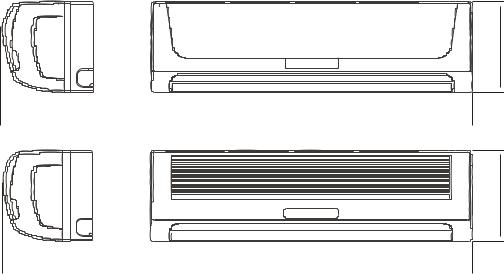
3.Dimensions
3.1 Indoor unit
Panel A
D |
|
|
|
|
B |
|||
|
|
|
|
|
|
|
|
|
|
|
|
|
|
|
|
|
|
C
Panel B
C
|
|
|
|
|
|
|
A |
|
|
|
B |
||
|
|
|
||||
|
|
|
|
|
|
|
|
A |
B |
C |
EL-KFR26G/TN2Y-A(B) |
214 |
750 |
250 |
EL-KFR36G/TN2Y-A(B) |
217 |
815 |
282 |
Page 7 of 33
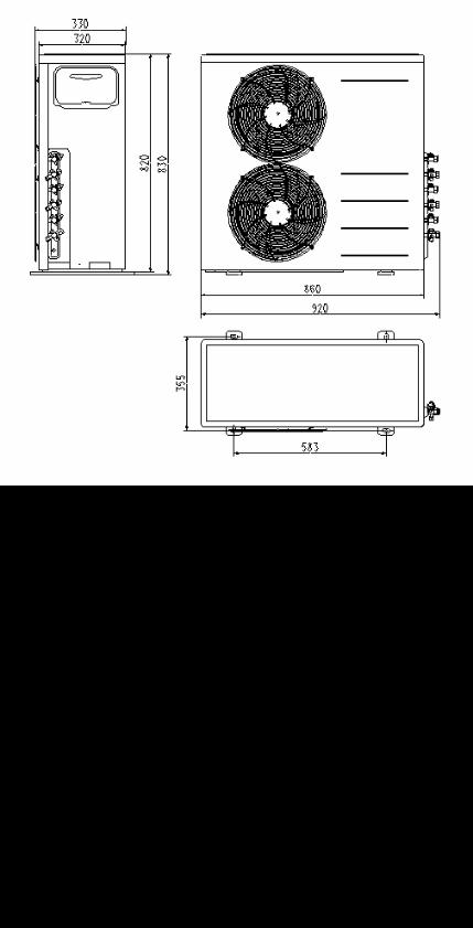
3.2 Outdoor unit
Outdoor unit 18K/21K
Outdoor unit 27K/30K
Page 8 of 33

4.Refrigeration cycle diagram
“1 drive 3 system” is made up of one “1 drive 1 system” and one “1 drive 2 system”.
PMV1
PMV2
SV2 SV1
T2 |
2 |
1 |
|
T1
Compressor
refrigeration distributor
1 drive 2 system
SV1 Primary four-way valve SV2 Secondary four-way valve PMV1 PMV2 Electronic expansive valve T1 T2 Indoor pipe temperature sensor
Condenser
Four-way valve
Evaporator
Compressor
1 drive 1 system
Notice For 1 drives 2 system, there are two individual refrigerant circuit and two compressors, but for the 1drive 2 system in the 1 drive three system, there is only one refrigerant circuit and only one compressor.
Page 9 of 33
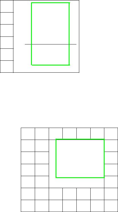
5.Operation limits
5.1Cooling operation
Outdoor unit air temp. DB
45
COOLING
17
-7
0 17 32 Indoor air temp. DB
Note: 1.The chart is the result from the continuous operation under constant air temperature Condition. However, excludes the initial pull-down stage.
2.The operation range below the dashed is the result added the low ambient kit.
5.2Heating operation
Indoor air temp. DB
30
25
20
15
10
5
-5 5 15 25 Outdoor unit air temp. DB
Note : The chart is the result from the continuous operation under constant air temperature conditions. However, excludes the initial pull-down stage.
Page 10 of 33
 Loading...