

Page 1
INSTRUCTION BOOK
GB
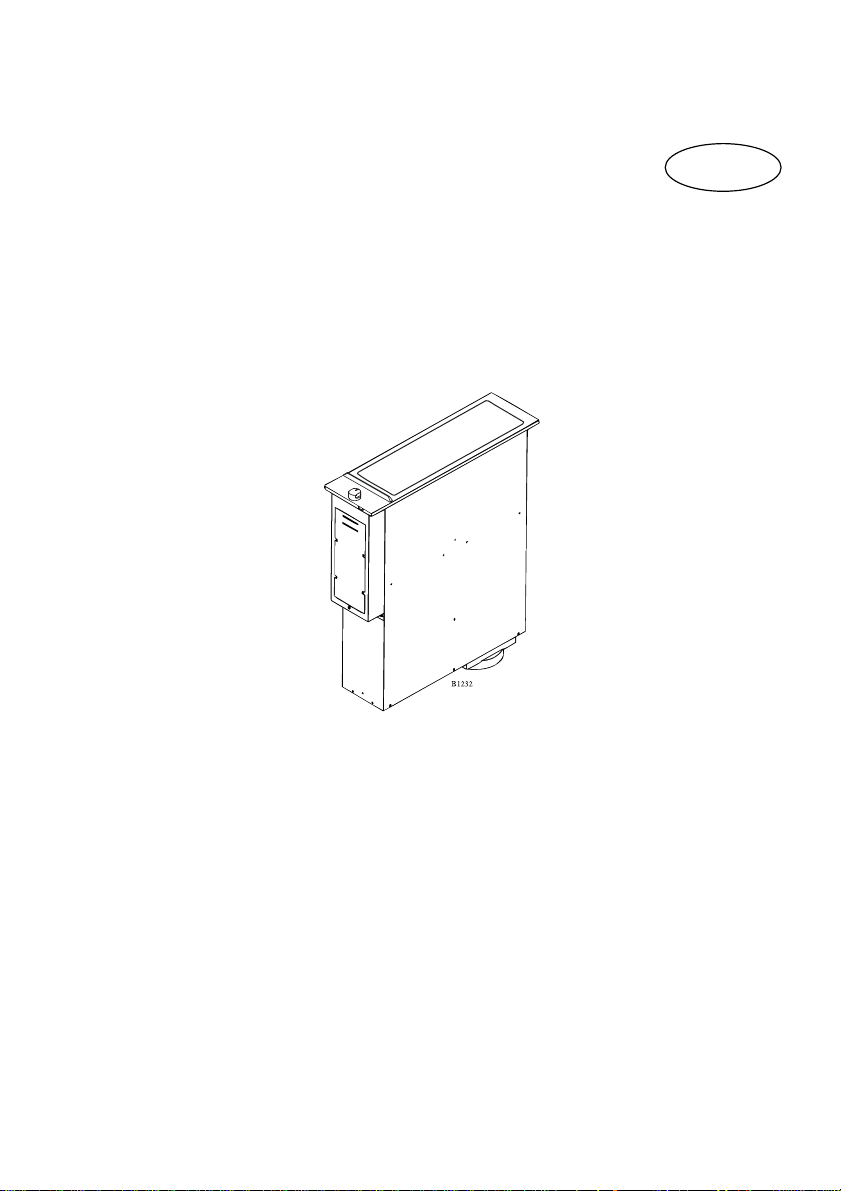
Downdraft worktop extractor
115 DD-m GB 949600730
1
Page 2

Your New Appliance
Thank you for purchasing an AEG appliance.
To enable you to use your new hob efficiently and safely, please read this
instruction book carefully before installing or using the appliance, and retain
for future reference. Should the hob be transferred to a new owner please
ensure this instruction book is left with the appliance in order that the new
owner can get to know the functions of the appliance and the relevant
warnings.
If you require further assistance or advice, please contact our Customer Care
Department either by letter or telephone:
Customer Care Department
AEG Domestic Appliances
55-77 High Street
Slough
SL1 1DZ
Tel: 08705 350350
2
Page 3
Table of contents
Content Page no.
For the user
Your new appliance ...................................................................................... 2
Safety information ........................................................................................ 4
Description of the product ......................................................................... 5
The functions of the worktop extractor ................................................ 5
Pilot light ............................................................................................... 6
How to use the worktop extractor ............................................................ 7
Operation .............................................................................................. 7
Choice of height and extraction speed ........................................7
Choice of extraction direction ..................................................... 8
Cleaning and maintenance ....................................................................... 10
Splashguard ........................................................................................ 10
Stainless steel surfaces ....................................................................... 11
Grease filter ........................................................................................ 12
Something not working ............................................................................. 18
Service and spare parts ............................................................................ 19
Guarantee conditions ................................................................................ 20
For the installer
Fitting .................................................................................................. 13
Installation .................................................................................................. 15
Electrical connnection ............................................................................... 16
Unpacking .................................................................................................. 17
Technical data ............................................................................................. 17
How to read the operating instructions:
1... 2...Step by step
Safety information
3
Hint and tips
Environmental information
Page 4
Safety information
These warnings are provided in the
interests of your safety. Ensure you
fully understand them before installing
or using the appliance. Your safety is of
paramount importance. If you are
unsure about the meaning of these
warnings contact the Customer Care
Department for assistance.
Installing
This hob must be installed according to
the instrucionts supplied. Any electrical
installation work must be undertaken
by a qualified electrician/ competent
person.
Do not alter the specifications or
attempt to modify the appliance in any
way.
During Use
This product is for domestic use only.
Maintenance and Cleaning
This appliance can be a fire hazard if
the grease filter is not cleaned
regularly
Service
Under no circumstances should you
attempt to repair the appliance
yourself. Repairs carried out by
inexperienced persons may cause
injury for more serious
malfunctioning. Contact your local
AEG Service Force Centre.
Never leave frying pans unattended
during use as overheated fat and oil
might catch fire.
Never do flambe cooking near this
extractor unit.
Child Safety
This appliance is designed to be
operated by adults. Children should not
be allowed to tamper with the controls
or play with the appliance.
4
Page 5
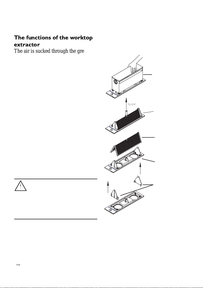
Description of the product
The functions of the worktop
extractor
The air is sucked through the grease
filter and then blown via the vent hose
to the vent duct and out into the
atmosphere.
As opposed to an ordinary extractor,
the worktop extractor is placed next to
the cooker. The worktop extractor can
be adjusted to two heights, the lower
and upper positions. For each height
there are two suction speeds to choose
from. It is always possible to select a
suitable height and suction speed
depending on what you fry and cook.
In addition to height and extraction
speed you can select extraction
direction. The worktop extractor can
be set to suck equally from the right
and left or to suck only from the right
or the left.
Top cabinet
Black plastic tube
Grease filter
Plastic tray
When the worktop extractor is
installed together with a gas
hob, the worktop extractor
must only be load in the upper
position. See the “installation”
section.
End pieces
5
Page 6
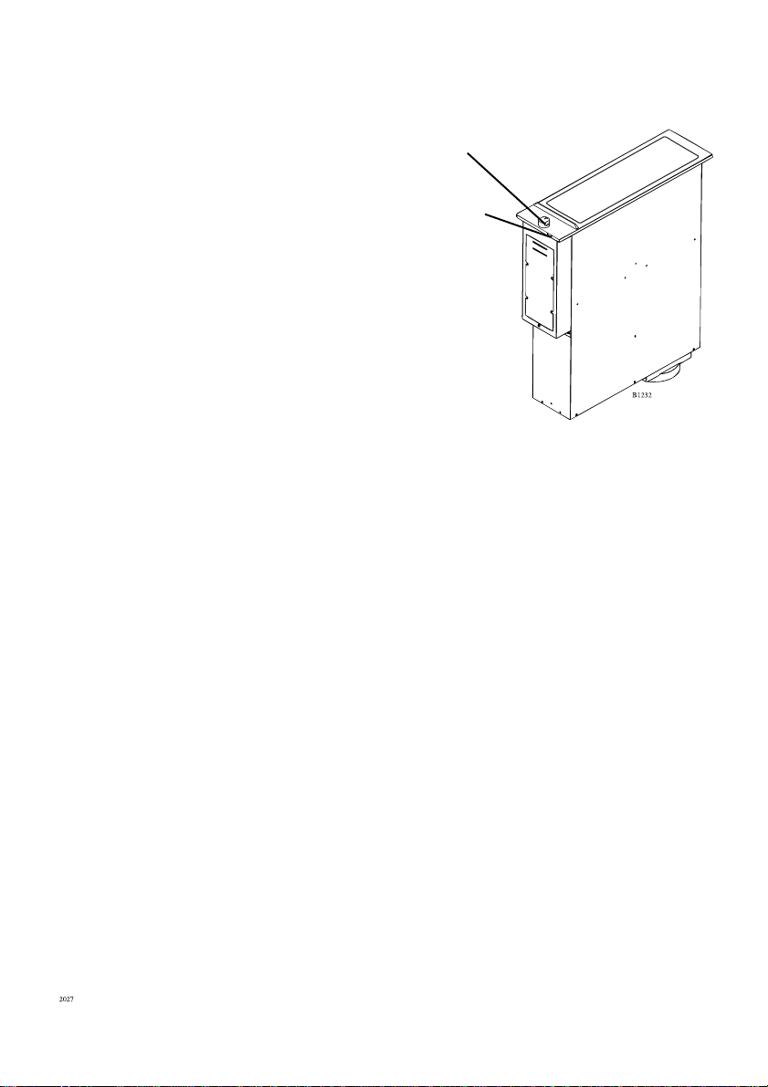
Pilot light
The pilot light is located on the front
of the product. The pilot light comes
on when the product is switched on
and extinguishes when the product is
switched off.
The extraction capacity of the
worktop extractor
The extraction capacity is 370m³/h at
the high extraction speed and 211m³/h
at the low extraction speed.
The extraction capacity of the worktop
extractor is reduced with every bend of
the vent hose/duct.
The capacity is also reduced in
proportion to any increase in the length
of the vent hose/duct. The less
resistance the exhaust air meets, the
better the extraction capacity and the
less noise from the worktop extractor.
If an installation has a 6 m long vent
hose (with a diameter of 125 mm) and
two 90˚ bends, the extraction capacity
will become max. 330 m³/h and min
190m3/h.
Control button
Pilot light
6
Page 7
How to use the worktop
extractor
Never leave the worktop
extractor unattended while
deep fat frying or heating fats
and oils. Do not flambé in
immediate vicinity of an
operating worktop extractor.
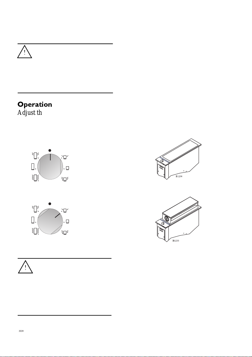
Operation
Adjust the height and extraction
speeds of the worktop extractor as
follows:
Worktop extractor disconnected
Worktop extractor in lower
position.
Low extraction speed
Switched off
High extraction speed
When the worktop
extractor is installed
together with a gas hob, the
worktop extractor must
only be load in the upper
position. See the
“installation” section.
7
Page 8
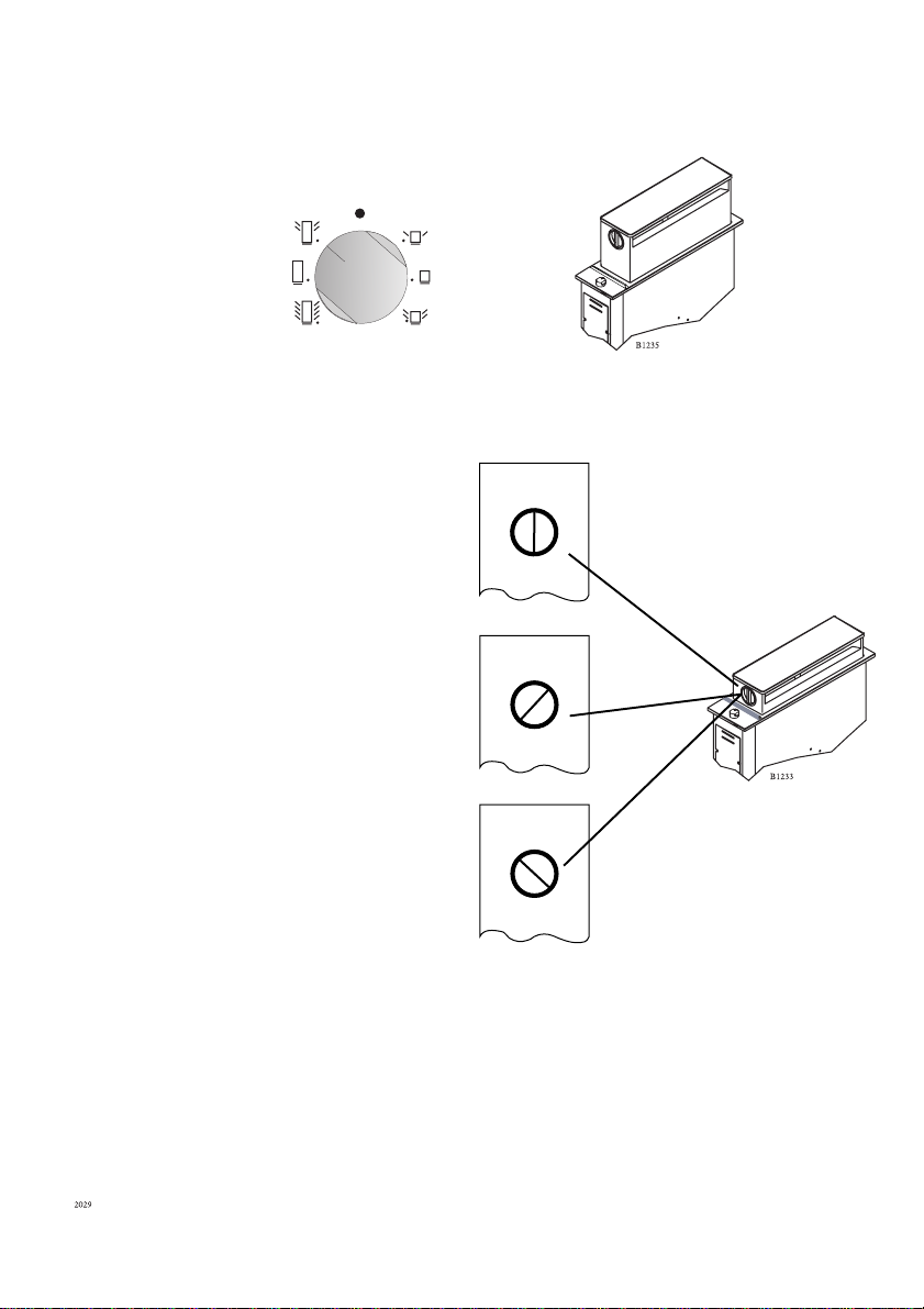
Worktop extractor in upper position.
Low extraction speed
Switched off
High extraction speed
Select the extraction direction as
follows:
Extraction from both the right and the
left
Extraction from the right
Extraction from the left
8
Page 9

Use the worktop extractor
correctly
To have the worktop extractor
working correctly, the kitchen
windows should be kept closed to
lower the pressure in the room.
On the other hand to obtain maximum
effect a window should be open in
another room.
9
Page 10

Cleaning and maintenance
Before carrying out any
maintenance or cleaning isolate
the extractor from the mains
supply.
The extractor must be kept
clean as build up of grease or fat
can be a fire hazard
Splashguard
The splashguard can be removed to make
it easier to clean the surface.
What to do:
1. Hold the splashguard as shown
in the diagram
2. Lift the splashguard straight up
3. Clean the top surface as
described in “cleaning the steel
surface”
Be aware of the two retaining
pegs, which are sharp.
4. Replace the splashguard in
position ENSURE that it is
fitted the correct way round.
Never use hard or sharp
implements to lift off the
splashguard.
Do not wash the splashguard
in a dishwasher.
The hob must not be used
with the splashguard off.
10
Page 11

Stainless steel surfaces
Clean the appliance after use with a
soft cloth well wrung out in warm
water, use a small amount of liquid
detergent for stubborn soiling.
Stainless steel parts may become straw
coloured with use, use a proprietary
stainless steel cleaner to remove this
straw discolouration.
Never use metal wool, metal sponges
or other abrasive cleaning agents.
11
Page 12

Grease filter
To maintain optimum extraction
capacity of the worktop extractor and
to avoid fire hazards, the grease filter
should be cleaned at least once a
month.
Proceed as follows:
1. Place the worktop extractor in the
upper extraction position.
2. Lift off the top cabinet. The top
cabinet can be washed in ordinary
washing up liquid or in a
dishwasher.
3. Lift off the black plastic tube – can
be cleaned in the same way as the
top cabinet.
4. Lift off the grease filter – can be
cleaned in the same way as the top
cabinet.
5. To ease cleaning of the plastic tray,
the end pieces can be lifted off and
cleaned in the same way as the top
cabinet.
The worktop extractor must not
be activated when the top
cabinet is not fitted.
12
Page 13

Fitting
The worktop extractor can be fitted in
any type of kitchen worktop with a
thickness of between 28 and 40 mm.
Location
It is recommended that you install the
worktop extractor in continuation of
the hob. If two or more hobs are
installed, the worktop extractor should
be placed between the units so that you
can take full advantage of the variable
extraction direction.
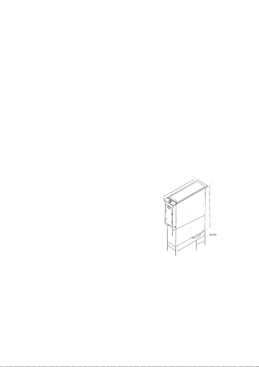
Clamping
When the worktop extractor is fitted,
the enclosed clamp should be fitted in
the slot which best fits the thickness of
the kitchen worktops or the worktop
frame. Secure the clamp with a
manual screwdriver.
Dimensions
The hole for the chosen combination
must be cut as a rectangular hole. The
width of the hole is always: 490 mm
for all combinations.
The length of the hole equals the sum
of the external measures of length of
all the units - 20 cm.
Minimum distance
to side wall:
150 mm
Reinforcement
beams
13
Minimum distance
to rear wall (nonflammable material):
50 mm
Page 14

Fitting reinforcement beams
All 145 mm and 290 mm units come
with a reinforcement beam. A
reinforcement beam must be fitted
between each unit. The beam should
not be screwed onto the worktop, but
be kept in place by the frame section
of the units.
145 mm:
Worktop extractor
290 mm:
Ceramic glass with two hotplates
Gas with two burners
Solid plate with two hotplates
Combi-grill/fryer
Ceramic grill
Wok
Fryer
580 mm:
Ceramic glass with four hotplates
Gas with four burners
The capacity is also reduced in
proportion to any increase in the length
of the vent hose/duct. The less
resistance the exhaust air meets, the
better the extraction capacity and the
less noise from the worktop extractor.
If an installation has a 6 m long vent
hose (with a diameter of 125 mm) and
two 90˚ bends, the extraction capacity
will become max. 330 m³/h and min
190m3/h.
720 mm:
Ceramic glass with four hotplates
The extraction capacity of the
worktop extractor
The extraction capacity is 370m³/h at
the high extraction speed and 211m³/h
at the low extraction speed.
The extraction capacity of the worktop
extractor is reduced with every bend of
the vent hose/duct.
14
Page 15

Installation
This extractor unit must be
installed according to the
instructions supplied. Any
electrical installation work must
be undertaken by a qualified
electrican/competent person.
Do not alter the specifications or
attempt to modify the appliance
in any way.
The ducting system for this
appliance must not be connected
any existing ventilation system
which is being used for any other
purpose.
Connection to outlet
Connection to a vent duct must be
carried out in accordance with current
regulations.
The work top extractor is supplied with
a connection piece to connect a pipe or
duct with a diameter of 125 mm.
Connection with a square pipe is
possible, but it requires individual
adjustment. The outlet of the extractor
without the connection piece is 159 x
152 x 100 mm.
15
Page 16

Electrical connection
The connection must be completely
tight regardless of the connection
chosen.
To install cable, remove front cover as
shown.
Connection
Min. cable dimension: 0.75 mm²
Cable type: HO5VV-F
IMPORTANT
Installation next to a gas unit
To install the work top extractor next
to a gas hob, proceed as follows:
Disconnect the wires from settings 1,
2, 4, 5 (blue, green, yellow, orange) of
the selector. Also disconnect green
and orange wires from setting 1 of the
micro switch. Do not reconnect these
two wires.
Insert a connecting wire between
settings 1, 2 and 4, 5 of the selector.
The connecting wires are located in the
lower right corner of the selector.
Reconnect blue wire to setting 1 and
yellow wire to setting 4. Now the
work top extractor can only be
operated in the upper position.
The extractor must be connected via an
external switch with a contact
gap of min. 3 mm (the main switch
may be used)
16
Blue
Green
Red
Yellow
Orange
Grey
Blue
Red
Yellow
Grey
Connecting wire
Page 17
132
433
125
490
600
145
510
Unpacking
Check that the worktop extractor has
no faults and is undamaged on
delivery.
Transport damage
Any damage from transport which
you have not carried out yourself must
be reported to the retailer within one
week of receipt.
Technical data
Electrical connections:
Voltage: 230-240 V
Max. power used: 90 watts
Electrical connection: 1 phase,
neutral and
earth
Serial number
You will find the serial number of the
hobs on the rating plate, which is on
the underside of the hob.
We recommned you write this number
on the cover of this instruction, so that
you have this information to in the
case of any service requirements.
Dimensions:
Maximum extraction speed: 370 m3/h
Minimum extraction speed: 211 m3/h
Outlet connection:
Round duct or hose: Ø 125 mm
Square duct: 100 x 150 mm
17
Page 18

Something not working
If the appliance is not working correctly, please carry out the following checks
before contacting your local AEG Service Force Centre.
IMPORTANT: If you call out an engineer to a fault caused by incorrect use or
installation, a charge will be made even if the appliance is under guarantee.
Symptom
Solution
The worktop extractor is not
working
If after all these checks, your appliance still does not operate correctly, contact
your local AEG Service Force Centre.
In-guarantee customers should ensure that the above checks have been made as
the engineer will make a charge if the fault is not a mechanical or electrical
breakdown.
Please note that it will be necessary to provide proof of purchase for any inguarantee service calls.
Check the worktop extractor is plugged
in and the electrical supply is swithced
on.
Check that the R.C.C.B. has not triped
(if fitted)
Check that the main house fuse has not
blown. Replace if necessary
18
Page 19

Service & spare parts
In the event of your appliance requiring service, or if you wish to purchase spare
parts, contact your local AEG Service Force Centre by telephoning:
08705 929 929
Your call will automatically be routed to the Service Centre covering your post
code area.
In-guarantee customers should ensure that the recommended checks under the
heading "Something Not Working" have been made as the engineer will make a
charge if the fault is not a mechanical or electrical breakdown.
Please note that proof of purchase is required for in-guarantee service calls.
Help us to help you
Please determine your type of enquiry before writing or telephoning. When you
contact us we need to know:
1. Your name, address, post code and telephone number
2. Clear and concise details of the fault.
3. Date of purchase
4. The model and serial number
This information can be found on the rating plate.
Customer Care
For general enquiries concerning your AEG appliance, or for further information
on AEG products, you are invited to contact our Customer Care Department by
letter or telephone:
Customer Care Department
AEG Domestic Appliances
55-77 High Street
Slough, Berkshire
SL1 1DZ
Tel 08705 350350
19
Page 20

Guarantee conditions
AEG offer the following guarantee to
the first purchaser of this appliance:
1. The guarantee is valid for 12
months commencing when the
appliance is handed over to the first
retail purchaser, which must be
verified by purchase invoice or
similar documentation.
2. The guarantee covers all parts or
components which fail due to faulty
workmanship or faulty material.
The guarantee does not cover
appliances where defects or poor
performance are due to misuse,
accidental damage, neglect, faulty
installation, unauthorised
modification or attempted repair,
commercial use or failure to
observe requirements and
recommendations set out in the
instruction book.
3. Should guarantee repairs be
necessary the purchaser must
inform the nearest AEG Service
Force Centre. AEG reserves the
right to stipulate the place of repair
(i.e., the customer's home, place of
installation or AEG workshop).
4. The guarantee or free replacement
includes both labour and materials.
5. Repairs carried out under guarantee
do not extend the guarantee period
for the appliance. Parts removed
during guarantee repairs become
the property of AEG.
6. The purchaser's statutory rights are
not affected by this guarantee.
European guarantee
If you should move to another country
within Europe then your guarantee
moves with you to your new home
subject to the following qualifications:
The guarantee starts from the date you
first purchased your product.
The guarantee is for the same period
and to the same extent for labour and
parts as exists in the new country of
use for this brand or range of products.
This guarantee relates to you and
cannot be transferred to another user.
The product is installed and used in
accordance with our instructions and is
only used domestically, i.e. a normal
household.
The product is installed taking into
account regulations in your new
country.
20
Page 21

Before you move please contact your
nearest Customer Care centre, listed
below, to give them details of your new
home. They will then ensure that the
local service organisation is aware of
your move and able to look after you
and your appliances.
France
Senlis +33 (0) 44 62 29 29
Germany
Nürnberg +49 (0) 911 323 2600
Italy
Pordenone +39 (0) 1678 47053
Sweden
Stockholm +46 (0) 8 738 79 10
UK
Slough + 44 (0) 1753 219899
21
Page 22

22
Page 23

23
Page 24

24
325 88-1550 Rev. 3-018
 Loading...