

Page 1

OPERATING INSTRUCTIONS
TKS-CS
Compact Station for Connecting the Solar Inverter to Medium Voltage
8000031355
EN
AEG Power Solutions GmbH, Warstein-Belecke
Department: PS AE
Revision: 01
Revision date: 15/10/2012 / Hagelstein
Released: 15/10/2012 / Songur
Document no.: 8000043213_BAL_en
Page 2

Compact Station TKS-CS - Operating Instructions
Revision Service
Status Revision Date Name
00 07/08/2012 Hagelstein
01 Corrections (pages 6, 15, 21) 15/10/2012 Hagelstein
Page 2 of 39 8000043213 BAL
Page 3

Table of Contents
Compact Station TKS-CS - Operating Instructions
1 General Information .................................................... 6
1.1 Validity .......................................................................... 6
1.2 Appropriate Use ............................................................ 6
1.3 List of Abbreviations ...................................................... 6
2 Safety ........................................................................... 7
2.1 Installation Location ....................................................... 7
2.2 Lightning Protection ....................................................... 7
3 Scope of Delivery ........................................................ 8
4 Equipment Specifications ........................................... 9
4.1 Structure ....................................................................... 9
4.2 Dimensions ................................................................. 10
4.3 Low-Voltage Box ......................................................... 10
4.3.1 AC Connections .......................................................... 11
4.3.2 ISO Small Distribution Box .......................................... 12
4.3.3 Communications Cabinet PV LoG-MH ........................ 13
4.3.4 Central Earthing System ............................................. 13
4.4 Medium-Voltage System ............................................. 14
4.5 Transformer................................................................. 15
5 Functional Description.............................................. 16
6. Transport ................................................................... 17
7 Assembly ................................................................... 18
7.1 Setting in Place ........................................................... 18
7.2 Installation ................................................................... 19
7.2.1 Low-Voltage Box ......................................................... 19
7.2.2 ISO Small Distribution Box .......................................... 20
7.2.3 Communication Interface PV.LoG-MH......................... 20
7.2.4 Central Earthing System ............................................. 21
7.2.5 Medium-Voltage System ............................................. 21
7.2.6 Medium-Voltage Transformer ...................................... 22
7.3 Tightening Torques for Screw Connections ................. 23
8 Start-up ...................................................................... 24
9 Operation ................................................................... 24
10 Servicing .................................................................... 25
10.1 Obligation to Keep a Written Record ........................... 27
10.2 Maintenance and Inspection ........................................ 28
10.2.1 Visual Inspection ......................................................... 28
10.2.2 Cleaning ...................................................................... 28
10.2.3 Functional Test ............................................................ 29
10.2.4 Testing/Measuring ....................................................... 29
10.2.5 Care ............................................................................ 30
10.2.5.1 Lubrication .................................................................. 30
10.2.5.2 Replacing the Axial Ventilator ...................................... 30
8000043213 BAL Page 3 of 39
Page 4

Compact Station TKS-CS - Operating Instructions
10.3 Repairs ........................................................................ 31
10.3.1 Testing after Repairs ................................................... 31
10.3.2 Replacement Work ...................................................... 31
10.3.2.1 Replacing the Transformer .......................................... 31
10.3.2.2 Replacing the MV Switchgear ..................................... 33
10.4 Maintenance Schedule ................................................ 34
10.5 Storing Spare Parts ..................................................... 35
11 Decommissioning and Dismantling ......................... 36
11.1 Removing Connection Cables ..................................... 36
11.2 Dismantling ................................................................. 36
11.3 Disposal ...................................................................... 37
11.3.1 Statutory Provisions .................................................... 37
11.3.2 Chemical System Components ................................... 37
List of Tables ............................................................................... 39
List of Figures ............................................................................. 39
Page 4 of 39 8000043213 BAL
Page 5

Compact Station TKS-CS - Operating Instructions
AEG Power Solutions GmbH
Emil-Siepmann-Strasse 32
59581 Warstein
Germany
+49 2902 763 100
Fax: +49 2902 763 645
E-mail: service.aegpss@aegps.com
Internet: http://www.aegps.com
8000043213 BAL Page 5 of 39
Page 6

Compact Station TKS-CS - Operating Instructions
1 General Information
1.1 Validity
These instructions relate to the technical specifications of the
equipment at the time of publication. These instructions are a
component part of the system.
Legal claims arising from this contractual relationship shall only be
recognised by AEG Power Solutions GmbH subject to the terms
agreed under the warranty obligation in the main contract.
1.2 Appropriate Use
The compact station TKS-CS is designed for use in solar power
stations with one or two Protect PV inverters, in accordance with
IEC 62271-202. The compact station is intended for outdoor
installation.
An output-related transformer for electrical isolation and outputdependent medium-voltage switchgear for feeding into the local
medium-voltage mains are installed in the compact station.
The equipment may only be used for this purpose. Any other use
constitutes misuse and can endanger personal safety.
1.3 List of Abbreviations
Abbreviation Meaning
CS Compact Station
MH Metal Housing
Further information can be found in the Protect PV Inverter Operating
Instructions (BAL).
Page 6 of 39 8000043213 BAL
Page 7

Compact Station TKS-CS - Operating Instructions
2 Safety
The qualified skilled personnel are responsible for safety.
The member of personnel who is responsible for the equipment
must ensure that only suitably qualified persons are allowed
access to the equipment.
To ensure safety in the electrical operating areas, these areas
should be lockable; i.e. suitable locking systems should be
installed by the owner on all exterior doors of the compact station.
2.1 Installation Location
The equipment is intended for use outdoors as an enclosed
electrical unit.
• Environmental conditions: ( technical data) in accordance
with DIN EN 60721-3-4.
• Freely accessible air vents for heat dissipation.
• Ground pressure: min. 250 kN/m
Refer to the technical data for additional criteria.
When selecting the installation location, regional regulations
governing noise emissions must be taken into account.
Do not install the equipment in areas subject to flooding or those
with a high groundwater level.
2
( excavation plan)
2.2 Lightning Protection
The connection to the potential equalisation system of the
foundation provides the equipment with effective protection against
lightning strikes.
The manufacturer’s specifications must be implemented effectively
in order to provide the photovoltaic system with suitable lightning
protection measures.
Further safety information can be found in the Protect PV Inverter Operating
Instructions (BAL).
8000043213 BAL Page 7 of 39
Page 8

Compact Station TKS-CS - Operating Instructions
3 Scope of Delivery
Check that the following components have been delivered with the
equipment:
• 1x compact station TKS-CS inc.:
• Technical documents comprising:
Available to order
AEG Service can also provide the following documents:
• Spare parts list
• Service book
To place an order, please contact:
AEG Power Solutions GmbH
Emil-Siepmann-Strasse 32
59581 Warstein
Germany
+49 2902 763 100
Fax: +49 2902 763 645
E-mail:
Internet: http://www.aegps.com
− Transformer corresponding to nominal output
− Medium-voltage system corresponding to nominal output
− Low-voltage box
− Power supply and auxiliary power supply
− Technical data
− Installation and operating instructions
− Drawings/circuit diagrams
service.aegpss@aeg.com
Page 8 of 39 8000043213 BAL
Page 9
Compact Station TKS-CS - Operating Instructions
4 Equipment Specifications
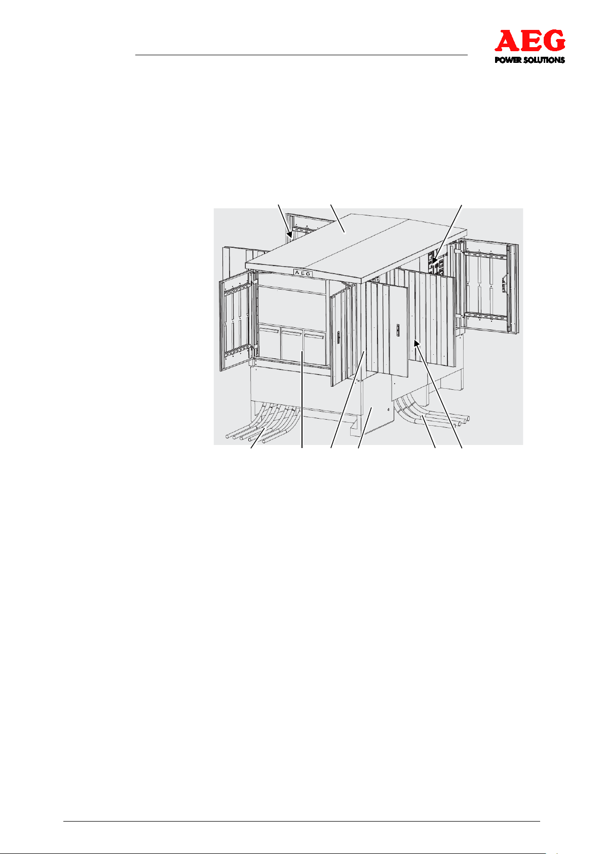
4.1 Structure
The compact station TKS-CS consists of a metal housing with a
detachable roof structure and a concrete base.
The concrete base comprises a warp-resistant foundation with an
oil and water-tight trough in the transformer compartment.
1 2 3
4 5 6 7 8 9
Figure 1 - Compact station TKS-CS
1 Transformer compartment
2 Roof structure
3 ISO small distribution box,
PV.LoG
4 MV branch - feed
5 MV switchgear
6 Wall structure
7 Concrete base
8 AC feed from MH
9 Low-voltage box
The wall and door structures are designed with double walls and
forced ventilation. An additional axial ventilator is installed in the
door of the transformer compartment for ventilation purposes.
8000043213 BAL Page 9 of 39
Page 10
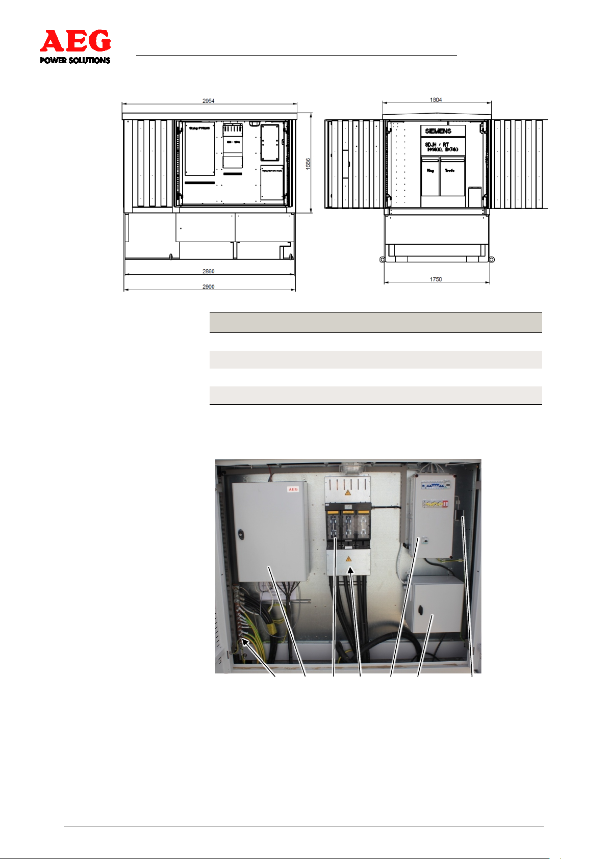
4.2 Dimensions
Compact Station TKS-CS - Operating Instructions
Figure 2 - Compact station side views
Dimension [mm]
Height of metal housing with roof 1686.5
4.3 Low-Voltage Box
Height of concrete base 780
MH depth (roof) 1750 (1804)
MH width (roof) 2900 (2954)
Table 1 - Dimensions
1 2 3 4 5 6 7
Figure 3 - Low-voltage box (example)
1 Central earthing system
2 Communications cabinet PV.LoG-MH
3 Load interrupter s witch, 3 -pin
4 LV connections with protective cover
Page 10 of 39 8000043213 BAL
5 ISO small distribution
box
6 Battery cabinet
7 Socket outlet with
earthing contact
Page 11
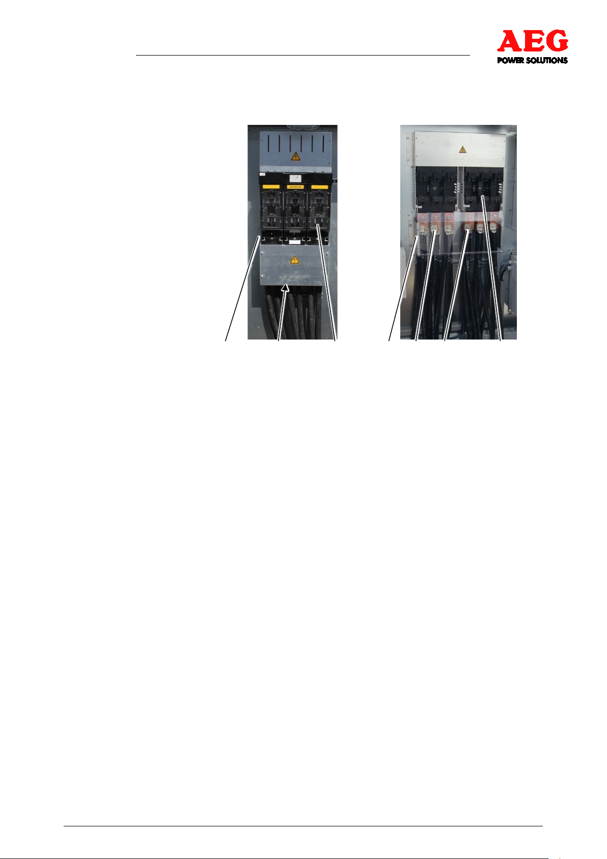
4.3.1 AC Connections
Compact Station TKS-CS - Operating Instructions
The low-voltage box must remain closed during operation.
1 2 3 4 5 5 3
Figure 4 - Low-voltage boxes (example)
1 LV box for an MH
2 AC connection - 1Q0 with steel
sheet protective cover
3 Load interrupter switch
4 LV box for two MH
5 AC connection -1Q0/ 2Q 0 with
Makrolon protective cover
8000043213 BAL Page 11 of 39
Page 12
Compact Station TKS-CS - Operating Instructions
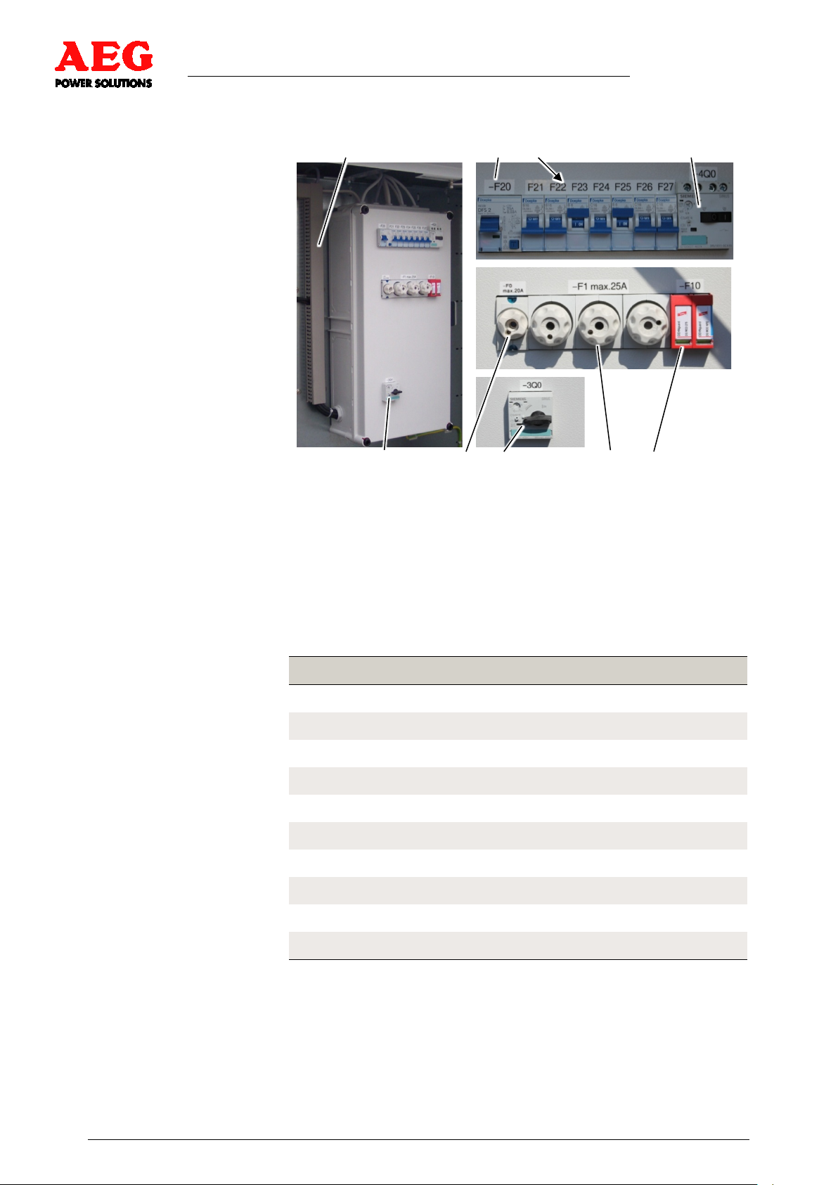
4.3.2 ISO Small Distribution Box
1 2 3 4
5 6 5 7 8
Figure 5 - ISO small distribution box (example)
1 Cable duct (internal)
2 -F20 - FI switch 25 A
3 F21 - 27 miniature circuit
breakers
4 -4Q0 - motor protection switch
6 -F0 - fuse max. 20 A
Sub-distribution
7 -F1 - fuses max. 25 A
Auxiliary transformer
8 -F10 - overvoltage protection
Fan
5 -3Q0 - motor protection switch
Auxiliary transf or mer
Fuse
F21
F22
F23
F24
F25
F26
F27
-F0
16 A Socket outlet with earthing contac t
16 A Door contacts and lighting
6 A Medium-voltage tripping
16 A Power supply PV.LoG-MH
6 A Axial fan
16 A optional
16 A optional
20 A Sub-distribution supply
-F1
-F10
Table 2 - Fuses
25 A Auxiliary transformer
Overvoltage protection
Page 12 of 39 8000043213 BAL
Page 13

Compact Station TKS-CS - Operating Instructions
4.3.3 Communications Cabinet PV LoG-MH
1
5
2 6
7
3
8
3 9
4
Figure 6 - PV.LoG-MH (example)
1 Data logger
2 Fuses
3 UPS 24 V DC
4 Short-circuit and
overvoltage protection
5 Ethernet coupler
6 Data acquisition boards
7 CAN overvoltage protection
8 Terminal strip
9 Shield terminals
The compact station TKS-CS features the PV.LoG-MH and a
variety of interfaces for monitoring and control.
Data exchange between the PV.LoG-MH and the MH station
control systems, the PV.IcX, and the transfer station takes place
via Ethernet, modbus, CAN bus and FO cables.
For further information, refer to the PV.LoG-MH Operating
Instructions.
4.3.4 Central Earthing System
1
2
3
4
5
6
7
Figure 7 - Central earthing system (example)
8000043213 BAL Page 13 of 39
Page 14

Compact Station TKS-CS - Operating Instructions
Sub-distribution
No.
1
2
3
4
5
6
7
Table 3 - Potential equalising strip
The central earthing system is preinstalled on the potential
equalising strip in the compact station.
4.4 Medium-Voltage System
H07V-K
[mm2]
70 Low-voltage box
95 Cable entry
70 Station housing
16
16 Communications cabinet PV.LoG-MH
70 Medium-voltage system
70 Transformer
Name
Figure 8 - MV switchgear (example)
The installed MV switchgear (example) is an interior system with
cable branch line (K) and transformer branch line (T) modules.
Further information on the MV switchgear is available in the
installation and operating instructions included in the scope of
delivery.
Page 14 of 39 8000043213 BAL
Page 15

4.5 Transformer
Compact Station TKS-CS - Operating Instructions
1 2 3 4 5 4 6
7 8 2
Figure 9 - Transformer (example)
1 Temperature sensor/indication
2 Earth terminal
3 MV porcelain isolator
4 MV connection to MV system
5 LV connection to LV box
6 Oil fill level valve
7 Transport securing device
8 Cooling fins
All internal connections to and from the transformer are
preinstalled in the compact station.
The transformer is on vibration dampers and is secured for
transport. The transport securing device does not need to be
removed for operation.
The transformer is equipped with temperature and oil level
monitoring equipment, which is connected to the PV.LoG-MH and
emits a warning if abnormal values occur.
For further information, refer to the transformer documentation.
8000043213 BAL Page 15 of 39
Page 16

Compact Station TKS-CS - Operating Instructions
=
~
PV.500-MH
PV.IcX
max. 1 to 8
PV.SuN
optional
PV.LoG-MH
Transfer station
Switchgear
PV.ControL
Transformer-
Monitoring
CAN bus, max. 2 x 500 m
FO, ring max. 4 km
Modbus/RS485, max. 2 x 500 m
Ethernet/COM server, max. 80 m
Power cable
TKS-CS.500
=
~
PV.500-MH
PV.IcX
max. 1 to 8
=
~
PV.500-MH
PV.IcX
max. 1 to 8
PV.SuN
optional
Transformer
PV.LoG-MH
Transformer-
Monitoring
Energy meter
Internet
connection
Radio and ripple
control /
power utility
interface
4 x relay
Transformer
RS485/current-voltage transformer
TKS-CS.1000
5 Functional Description
Figure 10 - Equipment diagram (example)
The station equipment is configured in accordance with the
required nominal output.
One or two Protect PV inverters can be connected to a compact
station TKS-CS.
The PV.Control or Skycontrol unit is adapted to the power station
capacity and the local feed conditions.
Further functional information can be found in the Protect PV Inverter
Operating Instructions (BAL).
Page 16 of 39 8000043213 BAL
Page 17

DANGER
6. Transport
Compact Station TKS-CS - Operating Instructions
Suspended loads during transport
Possibility of death or crushing.
Select lifting gear according to the total weight to be
transported.
Do not step under suspended loads.
Secure the danger zone.
Wear personal protective equipment.
8000043213 BAL Page 17 of 39
Figure 11 - Crane transport
The station may only be lifted using the crane rings on the
longitudinal sides. The crane rings on the face sides are only
intended for transport securing purposes and for dragging/towing
the stations while they are raised. Raising the stations using the
crane rings on the face sides is not permitted.
The load-carrying equipment used (ropes/belts) must have a
sufficient carrying capacity. The weight of the station is dependent
on the equipment configuration; please see the technical data.
The load must be evenly distributed between all four ropes/belts.
Lifting at one side is not permitted.
No people or objects may be on the platforms in front of the station
doors during lifting.
Page 18

7 Assembly
7.1 Setting in Place
Compact Station TKS-CS - Operating Instructions
The compact station TKS-CS does not need a foundation. The
concrete base serves as its foundation.
1 2 3 4 5 2 3 5
Figure 12 - Setting the compact station in place
1 Ground
2 Concrete base
4 Transport eyelets
5 Transport rod
3 Metal housing
Using the construction pit pin, create a construction pit on clear
ground.
The system may only be installed by crane
( Chapter 6 - Transport).
Remove the transport rod after the system has been installed.
Page 18 of 39 8000043213 BAL
Page 19

Compact Station TKS-CS - Operating Instructions
WARNING
i
7.2 Installation
7.2.1 Low-Voltage Box
i
Hinge side of the door when closing
Fingers or hands may be crushed.
Do not hold the hinge side of the door.
Take care while closing the cabinet door.
Observe the bending radius of the supply lines.
With one bend:
bending radius = 10 x diameter of supply line.
1
2
3
4
5
Figure 13 - LV box
1 LV box protective cover
2 Load interrupter NH4 - 1250 A
3 Connection panel NH4
(Cu busbars)
Connection Design *) Torque
L1-3:U, V, W max. 3x240 mm2, M12 2 15.5
PE max. 3x120 mm2, M12 2 15.5
4 Cable lug
5 Protective cover
(Nm)
*) 2 = cable lug connection
8000043213 BAL Page 19 of 39
Table 4 - LV box connections
1. Remove the protective cover from the connection panel.
The order of the conductors (L1, L2, L3) must be adhered to.
Page 20

Compact Station TKS-CS - Operating Instructions
2. Establish the AC power connections and PE connections using
the cable lug in accordance with the circuit diagram, and using
the relevant tightening torque.
3. Remove any cable debris and tools from the equipment and
replace the protective cover on the connection panel.
7.2.2 ISO Small Distribution Box
1 6
7
2 8
3
4 5
Figure 14 - ISO small distribution box (example)
1 Residual-current-operated circuitbreaker
2 Back-up fuse sub-distribution
3 Terminal strips
4 Motor protection switch
Auxiliary transformer
5 Screw connections
6 Miniature circuit breakers
7 Fuses, max. 25 A
8 Overvoltage protection
5
The ISO small distribution box is preinstalled in the compact
station.
To open the ISO small distribution box, unscrew the four screw
connections. The cover can then be pulled out towards the front.
Establish the connections in accordance with the circuit diagram.
7.2.3 Communication Interface PV.LoG-MH
The communications cabinet PV.LoG-MH includes batteries, which
are installed in the cabinet or in a separate box.
Install the communications cabinet PV.LoG-MH in accordance with
the PV.LoG installation instructions. Wiring is carried out in
accordance with the circuit diagram.
Data is exchanged between the PV.IcX combiner boxes or the
PV.ControL and the PV.LoG-MH via CAN bus ( *.USP and
operating instructions for PV.LoG and PV.ControL).
Page 20 of 39 8000043213 BAL
Page 21

Compact Station TKS-CS - Operating Instructions
7.2.4 Central Earthing System
Connect the active earthing to the potential equalising strip
according to the circuit diagram.
7.2.5 Medium-Voltage System
1 2
Figure 15 - Medium-voltage sy stem (ex ample)
1 Cable branch line L1/L2/L3 (left flap), external AC connections
2 Transformer branch line (right flap),
internal AC connections from transformer to load interrupter switch
The MV system is preinstalled in the compact station.
Use the power cables supplied for the system AC connections,
and connect in accordance with the manufacturer's installation
instructions located in the system. Insert the branch cable into the
compact station from below.
8000043213 BAL Page 21 of 39
Page 22

Compact Station TKS-CS - Operating Instructions
7.2.6 Medium-Voltage Transformer
1 2 2
3 4 5 6 3 4
Figure 16 - Transformer (example)
1 Earth connection
Transformer cover
2 LV connection with
porcelain isolator
3 MV porcelain isolator
4 MV elbow connector
5 Voltage tap changer
6 Retaining plate with cable clips
The oil transformer is preinstalled and wired in the compact
station TKS-CS. The LV connections are established in
accordance with DIN EN 50386. Transformer and MV connections
with porcelain isolators comply with DIN EN 504180.
During replacement work, establish the electrical cabling
connections as normal and connect the three earthing terminals
( manufacturer's technical operating documentation).
Page 22 of 39 8000043213 BAL
Page 23

Compact Station TKS-CS - Operating Instructions
7.3 Tightening Torques for Screw Connections
Thread
Electrical
connection
[Nm]
Cheese head
screw strength
category 5.8
Mechanical connection
Hexagon screw
strength category
8.8
[Nm] [Nm] [Nm]
Slotted cheese
head screw
DIN 84
M4
M5
M6
M8
M10
M12
M16
M20
M24
Table 5 - Tightening torques
1.2 1.3 2.0 1.2
2.0 2.65 4.0 2.0
3.0 4.4 7.0 2.5
6.0 10.5 17.0 3.5
10.0 - 33.0 4.0
15.5 - 56.0 -
30.0 - 140.0 -
52.0 - 260.0 -
80.0 - 445.0 -
These values apply to electrical and mechanical screw
connections. They do not apply to floor attachment with dynamic
stress applied.
8000043213 BAL Page 23 of 39
Page 24

DANGER
8 Start-up
Compact Station TKS-CS - Operating Instructions
Working with voltages up to 1 kV
Risk to life due to electric shock.
Comply with BGV A3, DIN VDE 0105-100 (EN 50110,
IEC 61243).
Skilled personnel with a Working with Live Current
certificate.
Special AEG Power Solutions software and hardware tools must
be used for initial start-up. Only skilled personnel trained by
AEG PS are in a position to use these tools correctly and to
perform initial start-up.
Once the equipment has been fully installed, the following aspects
must be checked:
• Screw connections properly tightened
• Cable connections properly established
• Tools removed
• Protective covers properly installed
9 Operation
The system is operated as a result of power emerging from the Protect PV
inverter; this is determined by the power plant control system.
Page 24 of 39 8000043213 BAL
Page 25

DANGER
DANGER
i
DANGER
DANGER
10 Servicing
Compact Station TKS-CS - Operating Instructions
Contact with voltage
Risk to life due to electric shock.
Press emergency off.
Move the victim away from live parts using dry insulating
material.
Get medical help and inform the control room.
Disconnect the equipment safely.
Working with voltages up to 1 kV
Risk to life due to electric shock.
Comply with BGV A3, DIN VDE 0105-100 (EN 50110,
IEC 61243).
Skilled personnel with a Working with Live Current
certificate.
DANGER
Residual voltage from capacitors
Risk to life due to electric shock.
Observe discharge time.
Disconnect the equipment safely.
Keep the equipment clean to minimise leakage currents.
Contact with leakage current
Risk to life due to electric shock.
Disconnect the equipment safely.
8000043213 BAL Page 25 of 39
Toppling of cargo during transport by industrial trucks
Possibility of death or crushing.
Lift cargo under its centre of gravity.
Secure the cargo and danger zone.
Wear personal protective equipment.
Page 26

Compact Station TKS-CS - Operating Instructions
WARNING
WARNING
WARNING
i
ATTENTION
Insufficient ventilation of e q u ipment
Equipment may overheat.
Keep air vents clear.
Ensure the equipment is sufficiently ventilated.
Heat generation in resistors
Risk of burning.
Do not touch hot components.
Hinge side of the door when closing
Fingers or hands may be crushed.
Do not hold the hinge side of the door.
Take care while closing the cabinet door.
Entry of water into electrical equipment
Risk to life due to electric shock.
Do not use water to clean the cabinets.
Do not place any vessels containing fluids (beverage cups,
5 safety rules
1. Disconnect safely.
2. Secure the equipment against being switched back on.
3. Verify that all poles are de-energised.
4. Earth the equipment, close the earthing switch and short-
5. Provide protection in the form of covers or barriers
for example) on electrical equipment.
circuit the equipment.
for any neighbouring live parts.
Page 26 of 39 8000043213 BAL
A safe disconnection certificate or a release certificate
i
according to DIN VDE 0105-100 (EN 50110) must be
presented prior to all maintenance and repair work.
The owner must draw up a safe disconnection procedure and
brief personnel on this.
Page 27

Compact Station TKS-CS - Operating Instructions
i
The owner is responsible for correct servicing of the systems and
the equipment. This also applies to system components that fall
within the responsibility of the grid operator.
In order to ensure uninterrupted availability of the equipment,
preventive servicing work should be carried out based on the
maintenance schedule. Regular maintenance reduces the risk of
breakdowns and disruption due to technical faults.
To maintain the validity of the warranty:
• Regular maintenance must be carried out and documented
according to the maintenance schedule.
• Only original AEG PS spare parts (or spare parts purchased
from AEG PS) may be used.
For further details, please refer to the provisions of the individual
contracts.
The owner must define work instructions for carrying out
servicing work, giving details of:
- Ambient conditions
i
- Tools, equipment, means of protection and auxiliary
equipment
- Suitable personal protective equipment and organisational
safety measures.
Servicing work must be carried out in accordance with
BGV A3 (DIN VDE 0100/VDE 0105) and DIN 31051
(DIN EN 13306).
AEG PS will rescind all obligations such as warranty
agreements, service contracts, etc. entered into by AEG PS or
i
10.1 Obligation to Keep a Written Record
Inspection results and details of any servicing work carried out
must be recorded in writing. Experience has shown that the best
way to document inspection results is in the form of a test report.
The following information must be recorded:
its representatives without prior notice, in the event of
anything other than original AEG PS spare parts being used.
• Maintenance schedule
• Date of the measure carried out
• Work performed
• Any special notes on the work performed
• Persons who carried out the work
• Signatures of the persons who carried out the work
• Signature of the person responsible (supervisor)
8000043213 BAL Page 27 of 39
Page 28

Compact Station TKS-CS - Operating Instructions
i
i
A correct test report, completed in full, is important for technicians
as evidence of exoneration in case of later complaints or for
investigations in case of damage. For this reason, test reports
should be retained for a long time (around 10 years).
10.2 Maintenance and Inspection
10.2.1 Visual Inspection
Visual inspections should be carried out in accordance with
DIN EN 13018.
Inspections must involve careful checks for the following in the
equipment:
• Mechanical damage
• Corrosion, thermal changes to and tightness of the
electrical connections
• Moisture
• Accumulation of conductive dirt or dust
• Defective fuses
• Foreign bodies
• Fans dirty or damaged (M2 and M3 when the waste air
duct is open)
• Filter mat dirty or damaged
Safety devices and warning notices should be checked for damage
and legibility.
If there is condensation in the equipment, the internal heating
device should be checked to determine whether it is working
properly.
10.2.2 Cleaning
Only equipment tested in accordance with DIN VDE 0680 may
be used for cleaning.
If there is condensation in the equipment parts that are to be
cleaned, cleaning must not be carried out.
The cleaning procedure used must comply with the relevant
regulations and provisions of the accident prevention regulation
VBG 4 "Elektrische Anlagen und Betriebsmittel" (Electrical
installations and equipment) and DIN VDE 0105-100 (Operation of
electrical installations). Only specially trained electricians may
carry out cleaning work when the equipment is live.
Page 28 of 39 8000043213 BAL
Page 29

i
10.2.3 Functional Test
Compact Station TKS-CS - Operating Instructions
The log for dry-cleaning low-voltage installations using a vacuum
cleaner must be completed before and after cleaning work. Circuit
and installation markings should be noted before cleaning, so that
if a marking is damaged or falls off, this can be rectified.
Always perform a functional test after completing any
i
Electrical equipment must only be started up if it is in perfect
working order and must be kept in this condition.
Following repair, replacement or modification work, a functional
test must be performed in accordance with the commissioning log.
For repeat tests, functional testing of the equipment or its
components need only be carried out to an extent that verifies the
safety of the equipment.
servicing work and before starting operation.
10.2.4 Testing/Measuring
The aim of testing/measuring is to verify that the electrical
equipment complies with the installation standards.
In the case of recurrent tests, all measurements must be taken in
accordance with the initial start-up and DIN VDE 0105100, and
compliance with all values/limits must be verified.
The equipment has various diagnostic functions (some of which
are optional), which can significantly reduce the time required for
maintenance work and troubleshooting.
Self-diagnosis:
This is activated when the equipment is switched on. Internal
auxiliary programs monitor the bus system, the control PCBs and
the sensors (amongst other things), and signal any faults that
occur.
Data logger:
Measured data, parameters and fault indications are saved
continuously. Measured data and performance data, as well as
fault histories, can be read out and evaluated as required.
i
All measuring and monitoring devices used for testing must
comply with the standards DIN VDE 0413/EN 61557 and
DIN 0404, and must be tested and calibrated regularly in
accordance with ISO 9001:2000.
The operating instructions describe how to output
performance and fault histories.
8000043213 BAL Page 29 of 39
Page 30

Compact Station TKS-CS - Operating Instructions
BGV A2 requires the owner to perform repeat tests at stipulated
times in order to verify that the electrical equipment is in perfect
working order.
At stipulated times, the owner must check that the fault current,
differential current and fault voltage protection devices are
functioning properly.
Carry out manual insulation testing.
10.2.5 Care
10.2.5.1 Lubrication
Carry out the following care measures for the station:
• Lubricate hinges, rods and guide rails after cleaning.
• Lubricate the ball bearings in the axial ventilator after
around 20,000 operating hours or a maximum of 4 years,
according to the manufacturer's specifications.
10.2.5.2 Replacing the Axial Ventilator
WARNING
Rotating parts
Injury to fingers and hands possible.
Do not reach into rotating parts.
De-energise fans.
1 2 3 4 5 6
Figure 17 - Replacing the axial ventilator
1 Housing plate with M9
2 Protective screen
3 Impeller
4 Connection cable with seal
5 Drive motor
6 Weather-proof cover
The axial ventilator must be replaced if it is defective or runs out of
round. As a precaution, it should be changed every 4 years (when
bearing lubrication is due).
Remove the axial ventilator in accordance with the manufacturer's
specifications and send it to the manufacturer for maintenance.
Page 30 of 39 8000043213 BAL
Page 31

Compact Station TKS-CS - Operating Instructions
10.3 Repairs
Only AEG PS skilled personnel may carry out repairs and
modifications on the compact station CS.xx.
If you want other personnel to carry out this work, this will need to
be authorised by means of written approval from AEG PS.
Only original AEG PS spare parts (or spare parts purchased from
AEG PS) may be used.
10.3.1 Testing after Repairs
Each time the equipment is repaired or modified, all recurrent
tests/measurements are to be carried out and documented in
accordance with DIN VDE 0105 (initial start-up log) once the work
is complete.
10.3.2 Replacement Work
10.3.2.1 Replacing the Transformer
The transformer can be accessed via the detachable roof or a
door. It can only be replaced when the roof structure has been
removed.
1 2 3 2
Figure 18 - Replacing the transformer, 1 (example)
1 Temperature sensor
2 Internal connections to
MV system
3 Internal connections from
low-voltage box
1. Disconnect the equipment safely.
2. Remove all connections from the transformer, and secure the
equipment.
8000043213 BAL Page 31 of 39
Page 32

Compact Station TKS-CS - Operating Instructions
i
1 2 3
Figure 19 - Station roof
1 Roof structure
2 Screw connection
3 Station frame
The roof structure weighs around 130 kg. Comply with
Directive 90/269/EEC (handling of loads).
3. Open all doors and unscrew the 6 roof structure screw
connections. Completely remove the roof structure from the
compact station TKS.CS ( roof removal: Bosecker).
1 2 3
Figure 20 - Replacing the transformer, 2 (example)
1 Low-voltage box
2 Transformer
4. Attach the transformer to the transport eyelets and carefully lift
it using lifting gear.
Page 32 of 39 8000043213 BAL
3 Transformer compartment
Page 33

Compact Station TKS-CS - Operating Instructions
5. Place a new transformer in the compact station's trough and
establish the connections. Finally, replace and align the roof
structure, and establish the screw connections ( transformer
operating instructions).
10.3.2.2 Replacing the MV Switchgear
1 2
3 4
Figure 21 - Partial top view TKS-CS (example)
1 Transformer compartment
2 Low-voltage box
3 Medium-voltage compartment
4 MV switchgear
1. Disconnect the equipment safely.
2. Remove all connections from the MV switchgear, and secure
the equipment.
3. Unscrew the screws of the MV switchgear and remove it from
the compact station using an industrial truck ( MV switchgear
BAL).
8000043213 BAL Page 33 of 39
Page 34

Compact Station TKS-CS - Operating Instructions
i
10.4 Maintenance Schedule
The maintenance schedule does not release the owner from his
obligation to create his own maintenance and operating
instructions for the location and to document them fully as quickly
as possible.
Maintenance instructions supplied by component manufacturers
must be included in the detailed specifications relating to the scope
of maintenance work.
Ongoing
Check the measured results of the equipment for plausibility.
Replace defective measuring instrumentation at the end of production.
Data bus:
Ongoing functional testing in operation.
For recurrent measurements and measurements after repair
work as per BGV A3, compliance with the DIN VDE 0105-100
inspection intervals is mandatory .
Monthly
Test lamps and replace diodes if required.
Check the function of the system's internal measuring instrumentation
by comparing the values during operation with the values displayed.
Check the function of the measuring instruments and accessory
systems required for operation and servicing.
Check the interior area and equipment for moisture and, if necessary,
establish the cause and dry the equipment.
Clean the interior areas of the compact station (operating area).
Every 6 months
Check the fastenings and function of the electrical connections of all
components in the compact station.
Check the function of the fault current, differential current and fault
voltage protective circuits.
Carry out recurrent measurements in accordance with DIN VDE 0105.
Check the axial ventilator for damage and whether it is working
correctly (rotation), and repair or replace if necessary.
Check the axial ventilator and weath er -proof cover for dirt, and clean if
necessary.
Check the function of the overtemperature warning system by opening
the sensor path.
Page 34 of 39 8000043213 BAL
Page 35

Compact Station TKS-CS - Operating Instructions
Annually
Measuring and monitoring devices must comply with the VDE 0413
standard.
Check and calibrate all measuring instruments.
Check that the equipment as a whole is in perfect working order:
- Check housing and roof structure for damage
- Check line connections for dirt and corrosion
- Check protective covers for damage and check their
fastenings
Check all input, monitoring and output values in the equipment and
also in interaction with the external control system. Check the control
behaviour of the equipment and readjust, correct or change the limit
values if required.
Check the function of the peripheral connections, i.e. all connections of
the various accessory systems, and repair them if required.
Clean the equipment to minimise creepage currents (do not use water).
Comply with BGV A3, DIN VDE 0105-100 during this process.
Check that the safety signs are complete and legible, and replace if
required.
(Must be checked by an expert every 2 years.)
Check the function of the lighting in the compact station, and rep lace if
necessary.
Every 2 years
Check of the safety signs in the operating area and in the equipment
by an expert.
Every 4 years
Replace the axial ventilator and clean the weather-proof cover.
10.5 Storing Spare Parts
i
The AEG PS customer service department will be happy to send
you a spare parts list on request.
When ordering spare parts, you must provide the component
designation, installation location and component number as
well as the unit number of the component.
8000043213 BAL Page 35 of 39
Page 36

Compact Station TKS-CS - Operating Instructions
i
11 Decommissioning and Dismantling
The compact station TKS-CS can be decommissioned or
dismantled for the purposes of changing its location or disposal.
Before beginning any work on the equipment, it must be deenergised. For this purpose, the five safety rules of electrical
engineering in accordance with DIN VDE 0105 (EN 50110) must
be observed:
5 safety rules
1. Disconnect safely.
2. Secure the equipment against being switched back on.
3. Verify that all poles are de-energised.
4. Earth the equipment, close the earthi ng switch and short-
circuit the equipment.
5. Provide protection in the form of covers or barriers
for any neighbouring live parts.
The owner must draw up a safe disconnection procedure and
brief personnel on this.
11.1 Removing Connection Cables
• Disconnect power terminals.
• Disconnect the power supply and auxiliary power supply.
• Disconnect all external control cables.
• Disconnect the earthing line clips from the central earthing
system.
11.2 Dismantling
DANGER
Suspended loads during transport
Possibility of death or crushing.
Select lifting gear according to the total weight to be
transported.
Do not step under suspended loads.
Secure the danger zone.
Wear personal protective equipment.
Page 36 of 39 8000043213 BAL
Page 37

11.3 Disposal
Compact Station TKS-CS - Operating Instructions
DANGER
Toppling of cargo during transport by industrial trucks
Possibility of death or crushing.
Lift cargo under its centre of gravity.
Secure the cargo and danger zone.
Wear personal protective equipment.
If necessary, secure the transformer to prevent it slipping.
Att ach suitable load-carrying eq uipment to the compact station
(using the transport eyelets on the concrete base).
Lift the equipment carefully and remove cables.
11.3.1 Statutory Provisions
Equipment at the end of its life is electrical scrap.
In commercial contexts, the manufacturer is responsible for the
disposal of electrical scrap unless otherwise agreed. Electrical
scrap must always be disposed of by an expert.
Electronic scrap consists of valuable materials which can be
reclaimed as secondary raw materials, but it also contains
environmentally harmful substances.
Commercial disposal companies have information on the best way
to recycle material (e.g. in the form of a Recycling Handbook).
For example, it is possible to recycle:
• PCBs and circuit boards
• Electronic components, EPROMs, ICs and relays
• Chips, processors, hard disks and drives
• Batteries
Electrical and electronic scrap may only be disposed of in
compliance with local legislation and regulations German
Electrical and Electronic Equip ment Act, 200 2/9 6/E C
(WEEE) and the Basel Convention.
11.3.2 Chemical System Components
AEG PS complies with the restrictions on the use of hazardous
substances in electrical and electronic units according to the
German Electric and Electronic Equipment Act Section 5
(2002/95/EC).
8000043213 BAL Page 37 of 39
Page 38

Compact Station TKS-CS - Operating Instructions
Do not dispose of old batteries with refuse. They contain
environmentally harmful materials (Hg, Cd or Pb).
Ensure compliance with local legislation and regulations
governing the storage, handli ng and disp os al of batteries.
Components such as plastics and insulating materials should be
disposed of as industrial waste and should be recycled.
Page 38 of 39 8000043213 BAL
Page 39

List of Tables
List of Figures
Compact Station TKS-CS - Operating Instructions
Table 1 - Dimensions ............................................................................... 10
Table 2 - Fuses ........................................................................................ 12
Table 3 - Potential equalising strip .......................................................... 14
Table 4 - LV box connections .................................................................. 19
Table 5 - Tightening torqu e s .................................................................... 23
Figure 1 - Compact station TKS-CS .......................................................... 9
Figure 2 - Compact station side views ..................................................... 10
Figure 3 - Low-voltage box (example) ..................................................... 10
Figure 4 - Low-voltage boxes (example) ................................................. 11
Figure 5 - ISO small distribution box (example) ...................................... 12
Figure 6 - PV.LoG-MH (example) ............................................................ 13
Figure 7 - Central earthing system (example) ......................................... 13
Figure 8 - MV switchgear (example) ........................................................ 14
Figure 9 - Transformer (example) ............................................................ 15
Figure 10 - Equipment diagram (example) .............................................. 16
Figure 11 - Crane transport ..................................................................... 17
Figure 12 - Setting the compact station in place ..................................... 18
Figure 13 - LV box ................................................................................... 19
Figure 14 - ISO small distribution box (example) .................................... 20
Figure 15 - Medium-voltage system (example) ....................................... 21
Figure 16 - Transformer (example) .......................................................... 22
Figure 17 - Replacing the axial ventilator ................................................ 30
Figure 18 - Replacing the transformer, 1 (example) ................................ 31
Figure 19 - Station roof ............................................................................ 32
Figure 20 - Replacing the transformer, 2 (example) ................................ 32
Figure 21 - Partial top view TKS-CS (example) ....................................... 33
8000043213 BAL Page 39 of 39
 Loading...