

Page 1
Instructions Manual
Manuel d’Instructions
Bedienungsanleitung
Gebruiksaanwijzing
Kullanim Kilavuku
EFA 90540 X
EFA 12540 X
Page 2

EN
Instructions Manual
INDEX
RECOMMENDATIONS AND SUGGESTIONS......................................................................................................................7
CHARACTERISTICS..............................................................................................................................................................8
INSTALLATION ....................................................................................................................................................................10
USE.......................................................................................................................................................................................14
MAINTENANCE....................................................................................................................................................................16
2
2
Page 3

FR
Manuel d’Instructions
SOMMAIRE
CONSEILS ET SUGGESTIONS ..........................................................................................................................................18
CARACTERISTIQUES.........................................................................................................................................................19
INSTALLATION ....................................................................................................................................................................21
UTILISATION........................................................................................................................................................................25
ENTRETIEN..........................................................................................................................................................................27
3
3
Page 4

DE
Bedienungsanleitung
INHALTSVERZEICHNIS
EMPFEHLUNGEN UND HINWEISE....................................................................................................................................29
CHARAKTERISTIKEN..........................................................................................................................................................30
MONTAGE............................................................................................................................................................................32
BEDIENUNG.........................................................................................................................................................................36
WARTUNG............................................................................................................................................................................38
4
4
Page 5

NL
Gebruiksaanwijzing
INHOUDSOPGAVE
ADVIEZEN EN SUGGESTIES.............................................................................................................................................40
EIGENSCHAPPEN...............................................................................................................................................................41
INSTALLATIE .......................................................................................................................................................................43
GEBRUIK..............................................................................................................................................................................47
ONDERHOUD ......................................................................................................................................................................49
5
5
Page 6

TR
Kullanim Kilavuku
IÇERIKLER
TAVSIYELER VE ÖNERILER ..............................................................................................................................................51
ÖZELLIKLER........................................................................................................................................................................52
MONTAJ...............................................................................................................................................................................54
KULLANIM............................................................................................................................................................................58
BAKIM...................................................................................................................................................................................60
6
6
Page 7
EN
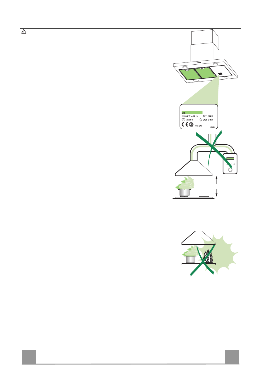
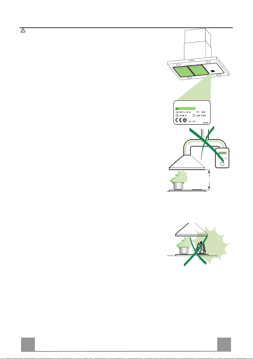
RECOMMENDATIONS AND SUGGESTIONS
650 mm min.
The Instructions for Use apply to several versions of thi s appliance. Ac-
cordingly, you may find descriptions of individual features that do not apply to your specific appliance.
INSTALLATION
• The manufacturer will not be held liable for any damages resulting fr om
incorrect or improper installation.
• The minimum safety distance b etween the cooker top and the extr actor
hood is 650 mm.
• Check that the mains voltage corres ponds to that i ndicated on the rati ng
plate fixed to the inside of the hood.
• F or Class I appliances, check t hat the domestic power s upply guara ntees
adequate earthing.
Connect the extractor to the exhaust fl ue through a pipe of minimum di -
ameter 120 mm. The route of the flue must be as short as possible.
• Do not connect the extractor hood to exhaust ducts carrying combustion
fumes (boilers, fireplaces, etc.).
• If the extractor is us ed in conjunction with non -electrical appliances (e. g.
gas burning appliances), a sufficie nt degree of aeration must be guara nteed in the room in order to prevent the backflow of exhaust g as. The
kitchen must have an opening communicati ng directly wi th the open air in
order to guarantee the entry of clean air.
USE
• The extractor hood has been designe d exclusively for domestic use to
eliminate kitchen smells.
• Never use the hood for purposes other than for which it has ben designed.
• Never leave high naked flames under the hood when it is in operation.
• Adjust the flame intensity to direct it onto the bottom of the pan only, m aking sure that it does not engulf the sides.
• Deep fat fryers must be continuously moni tor ed du ring use: overheated oil
can burst into flames.
• Do not flambè under the range hood; risk of fire
• This appliance is not intended f or use by pe rsons (incl uding c hildr en) wit h
reduced physical, sensory or mental capabilities, or lack of experience
and knowledge, unless they have been given supervision or instruction
concerning use of the appliance by a person responsible for their safety.
• Children should be supervised to ensure that they do not pl ay with the
appliance
MAINTENANCE
• Switch off or unplug the appl iance from the m ains supply before carrying
out any maintenance work.
• Clean and/or replace the Filters after the specified time period.
• Clean the hood using a damp cloth and a neutral liquid detergent.
7
7
Page 8
EN
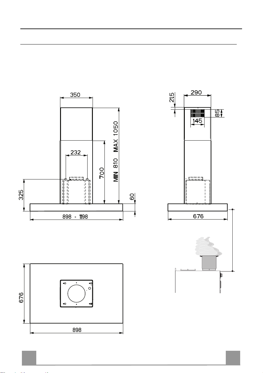
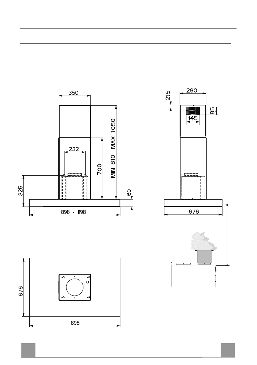
CHARACTERISTICS
Dimensions
650 min.
8
8
Page 9
EN
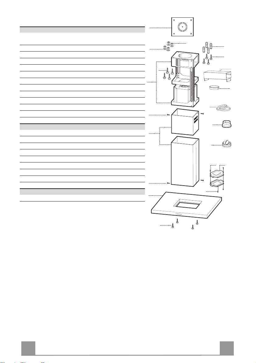
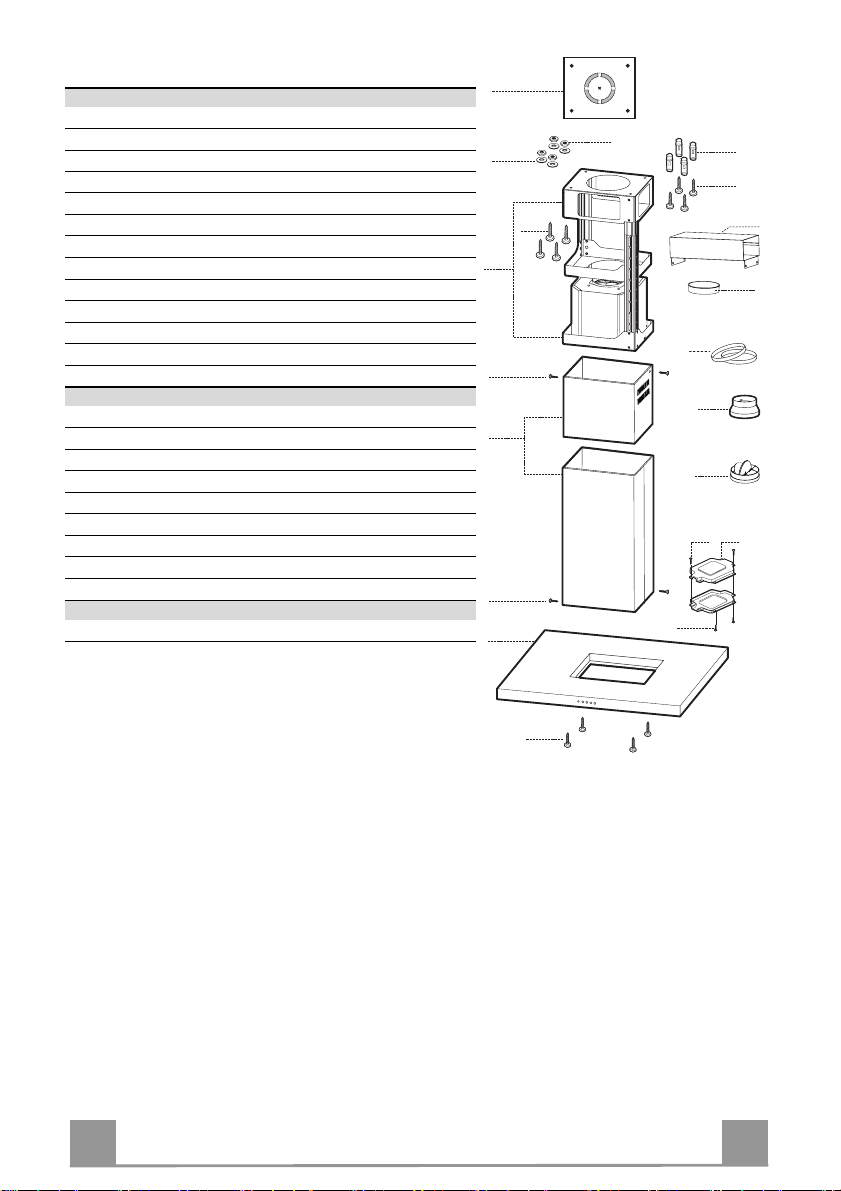
Components
Ref. Q.ty Product Components
1 1 Hood Body, complete with: Controls, Light, Blower,
Filters
2 1 Telescopic Chimney comprising:
2.1 1 Upper Section
2.2 1 Lower Section
7.1 1 Telescopic frame compl ete with extractor, consi sting of:
7.1a 1 Upper frame
7.1b 1 Lower frame
9 1 Reducer Flange ø 150-120 mm
10 1 Flange ø 150
10a 1 Dumper ø 150mm
15 1 Air Outlet Connection
24 1 Junction box
25 2 Pipe clamps
Ref. Q.ty Installation Components
11 4 Wall Plugs ø 10
12c 6 Screws 2,9 x 6,5
12e 2 Screws 2,9 x 9,5
12f 4 Screws M6 x 10
12g 4 Screws M6 x 80
12h 4 Screws 5,2 x 70
21 1 Drilling template
22 4 6.4 mm int. di a washers
23 4 M6 nuts
Q.ty Documentation
1 Instruction Manual
7.1
21
22
12c
2
12c
1
7.1a
12g
7.1b
2.1
2.2
23
12c
25
12e
11
12h
15
10
9
10a
24
12f
9
9
Page 10
EN 110
INSTALLATION
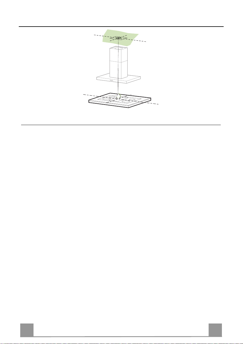
Drilling the Ceiling/shelf and fixing the frame
DRILLING THE CEILING/SHELF
• Use a plumb line to mark the centre of the hob on the ceiling/support shelf.
• Place the drilling template 21 provided on the ceiling/support shelf, making sure that the
template is in the correct position by lining up the axes of the template with those of the hob.
• Mark the centres of the holes in the template.
• Drill the holes at the points marked:
• For concrete ceilings, drill for plugs appropriate to the screw size.
• For hollow brick ceilings with wall thickness of 20 mm: drill ø 10 mm(immediately insert
the Dowels 11 supplied).
• For wooden beam ceilings, drill according to the wood screws used.
• For wooden shelf, drill ø 7 mm.
• For the power supply cable feed, drill ø 10 mm.
• For the air outlet (Ducted Versio n), drill according to t he diameter of the external air exhaust duct connection.
• Insert two screws of the following type, crossing them and leaving 4-5 mm from the ceiling:
• For concrete ceilings, use the appropriate plugs for the screw size (not provided).
• for Cavity ceiling with inner space, with wall thickness of approx. 20 mm, Screws 12h,
supplied.
• For wooden beam ceilings, use 4 wood screws (not provided).
• For wooden shelf, use 4 screws 12g with washers 22 and nuts 23, provided.
Page 11
EN 111
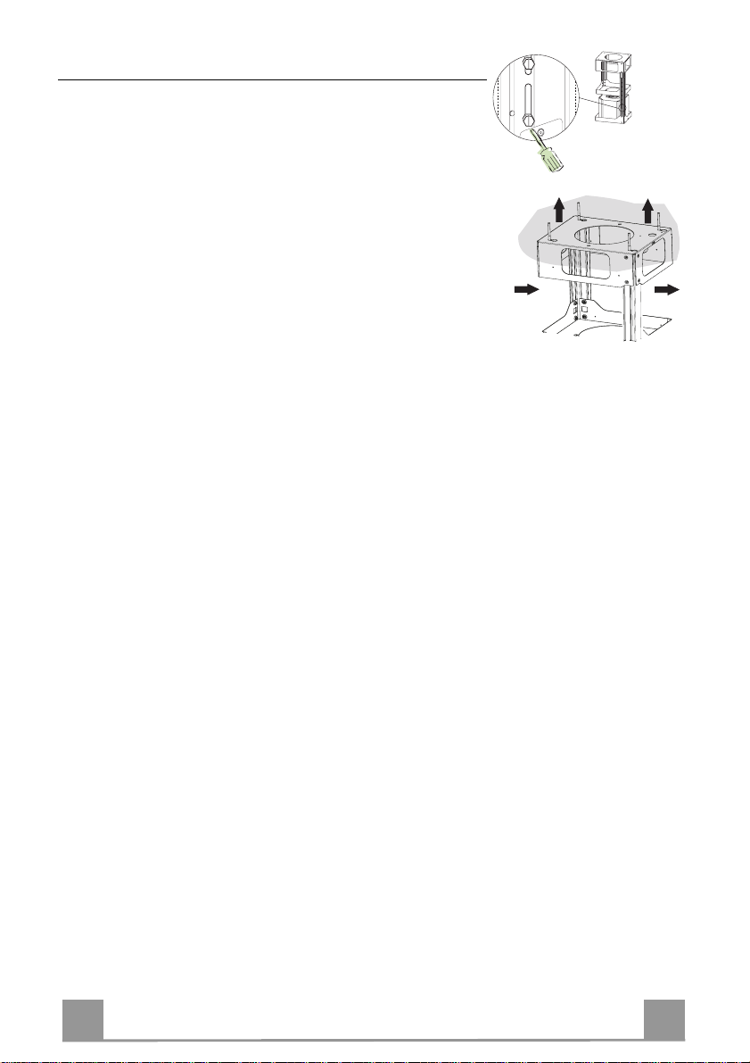
Fixing the frame
2
2
1
1
• Loosen the two screws fasten ing the lower chimney and remove this from the lower frame.
• Loosen the two screws fastening the upper chimney and remove this from the upper frame.
If you wish to adjust the height o f the frame, proceed as follows:
• Unfasten the eight metric screws joining the two columns, located at the sides of the frame.
• Adjust the frame to the h eight required, then replace all t he
screws removed as above.
• Insert the upper chimney stack from above, and leave it running free on the frame.
• Lift up the frame, fit the frame slots onto the screws up to the
slot end positions.
• Tighten the two screws and fasten the other two screws provided with the hood.
Before tightening the screws completely it is possible to adjust
the frame by turning it. Make sure that the screws do not come
out of their seats in the slotted holes.
• The frame mountings must be secure to withstand the weight
of the hood and any stresses caused by the occasional side
thrust applied to the device.
On completion, check that the base is stab le, even if the frame
is subjected to bending.
• In all cases where the ceiling is not strong enough at the suspension point, the installer must provide strengthening using
suitable plates and backing pieces anchored to the structurally
sound parts.
Page 12
EN 112
Connections
ø 120
25
9
10a
10a
ø 150
25
15
10
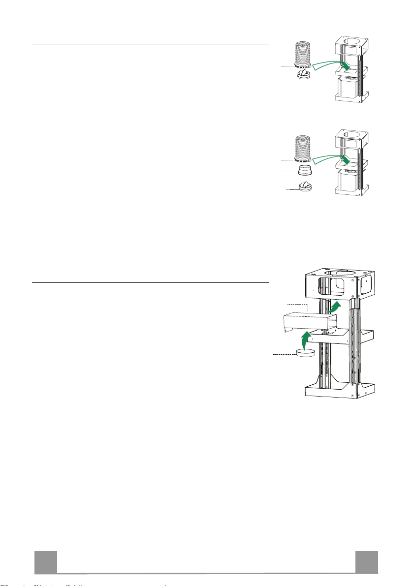
DUCTED VERSION AIR EXHAUST SYSTEM
When installing the ducted version, connect the hood to the
chimney using either a flexible or rigid pipe ø 150 or 120mm, the
choice of which is left to the installer.
To install a ø 150
• To install the dumper 10a.
• Fix the pipe in position using sufficient pipe clamps (not supplied).
To install a ø 120
• To install a ø 120 mm air exhaust connection, insert the reducer flange 9 on the dumper 10a.
• Fix the pipe in position using sufficient pipe clamps (not supplied).
• Remove any activated charcoal fil ters.
Recirculation version air outlet
• Fix the connection 15 to the frame using the 4 screws provided.
• Fix the flange 10 to the lower opening of the connection 15.
• Connect the hood air outlet to the flange in the lower part of
the junction using a rigid or flexible ø 150 tube (by installer’s
choice).
Page 13
EN 113
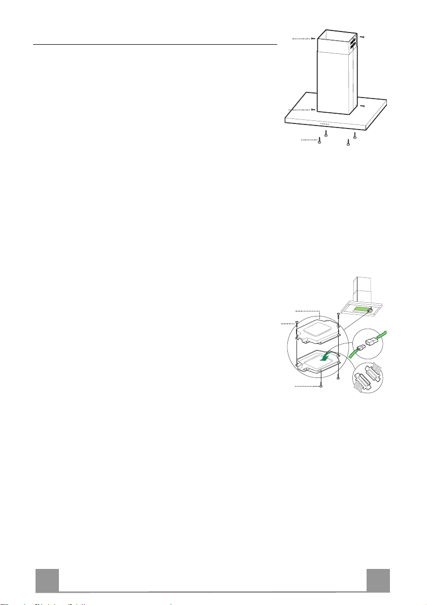
Flue assembly - Mounting the hood body
12f
12c
12c
24
12e
Cmd
12c
Lux
• Position the upper chimney section and fix the upper part to the
frame using the 2 screws 12c (2,9 x 6,5) provided.
• Similarly, position the lower chimney section and fix the
lower part to the frame using the 2 screws 12c (2,9 x 6,5) provided.
Before fixing the hood body to the frame:
• Remove the grease filters from the hood body.
• Remove any activated charcoal fil ters.
• From below, use the 4 screws 12f (M6 x 10)provided to fix the
hood body to the frame.
ELECTRICAL CONNECTION
• Connect the hood to the mains through a two-pole switch having a contact gap of at least 3 mm.
• Re move the grease filters (see paragraph Maintenance) being
sure that the conn ector of the feeding cable is correctly inserted
in the socket placed on th e side of the fan.
• Connect the control connector Cmd.
• Connect the lights connecto r Lux.
• Place th e connectors in the junction box 24 and close it using
the 2 screws 12e (2,9 x 9,5) provided.
• Fix the junction box to the hood body using the 2 screws 12c
(2,9 x 6,5) provided.
• For the recirculation version, fit the activated carbon odour filter.
• Replace the grease filters.
Page 14
EN 114
USE
Dual Function
L T1 T2 T3 T4 T5 F
The hood can be switched on pushing directly onto the requested speed without firstly having to select 0/1 button .
Touch
control
T1
T2
T3
T4
Basic functions
When briefly pressed it switches the lighting system
L
on and off.
When pressed for 2 seconds it starts the lighting
system in “courtesy light” mode. The lamps are
fed at a reduced power of approximately 5W.
Such function can be stopped by pressing the
touch control for 2 seconds or just by pressing it
shortly in order to return to the normal lighting
mode. In courtesy light mode the touch control is
not lit.
When pressed the motor is stopped, regardless of the
speed it is set to.
When pressed the motor is set to the first speed
By a brief pressing the motor is set to the second
speed.
By pressing the touch control for approximately 2
seconds the Delay function is enabled, i.e dela-
yed shutdown of the appliance ensuring a com-
plete elimination of the residual odours. This fun-
ction can be activated at OFF-position and at 1°,
2° and 3°speeds. It can be stopped in advance
by pressing any of the touch controls (T) with the
exception of T3. The Delay function works accor-
ding to the following scheme:
1°speed / OFF = 20 minuets
2°speed = 15 minutes
3°speed = 5 minutes
When pressed the motor is set to the third speed
Indicator lights
Touch control unlit Lights off
Touch control lit Lights on
Touch control unlit Courtesy light on
Touch control lit Motor on
Touch control unlit Motor off
Touch control lit
Touch control lit Second speed on
Flashing touch
control
Touch control lit
Delay function on
Page 15
EN 115
Touch
Touch control lit
control
T5
Basic functions Indicator lights
When pressed the motor is set to the intensive speed
timed to 5 minutes. At the end of 5 minutes of intensive speed the hood starts again at the speed it was set
to previously. In case the hood is set to the intensive
speed directly from OFF-state it will then start from
the first speed after 5 minutes of intensive speed.
When pressed for 4 seconds it resets the filter alarm
F
signal indicated by flashing of the touch control T1.
This procedure can be carried out only when the
motor is stopped.
Flashing touch
control
Touch control lit
Metal grease filters saturation alarm. Metal gr e ase
filters need to be washed.
The alarm star ts up after
100 working hours.
Charcoal odour filter saturation alarm. Char coal
filter has to be replaced
and metal grease filters
washed. The alarm starts
up after 200 working
hours. (Activation; chec k
the paragraph “Odour
filter”)
Page 16
EN 116
MAINTENANCE
REMOTE CONTROL (OPTIONAL)
The appliance can be controlled using a remote control powered
by a 1.5 V carbon-zinc alkaline batteries of the standard LR03AAA type.
• Do not place the remote control near to heat sources.
• Used batteries must be disposed of in the proper manner.
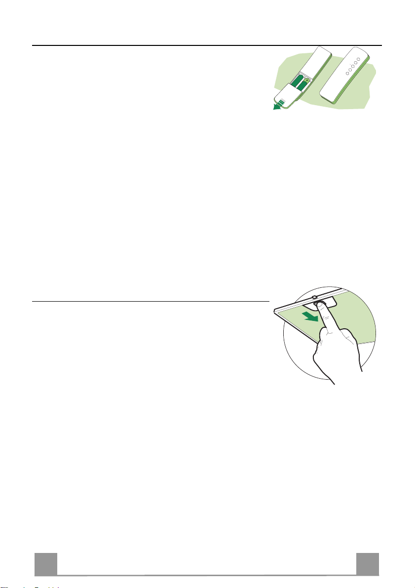
Grease filters
CLEANING OF THE METAL CASSETTE FILTERS
Alarm reset
• Stop the motor.
• Press the F -touch control for at least 4 seconds until the T1 -
touch control flashes.
Cleaning the filters
• Filters can be washed in the dish machine. They need to be
washed every 2 mont hs o r even more fr equ en tly in case of particularly intensive use of the hood.
• Remove the filters one by one pushing them towards the back
side of the unit and simultaneously pulling downwards.
• Any kind of bending of the filters has to be avoided when
washing them. Before fitting them again into the hood make
sure that they are completely dry.
• When fitting the filters into the hood pay attention that they are
mounted in correct position and that the handle faces outwards.
Page 17
EN 117
Odour filter (Recirculation Version)
This filter cannot be washed or regenerated, and must be replaced when the F touch control starts
to flash, or at least once ev e ry 4 months. The alarm is only trigge re d w he n the m otor is on.
Enabling/Disabling the alarm signal
• In Recirculation Version Hoods, the Filter saturation Alarm must be enabled at the time of
installation or later.
• Switch off the lights and the motor.
• Disconnect the mains power supply to the hood by removing the motor unit power supply
cable connector, switching off the power supply at the Mains or turning the Main switch off.
• Restore the connection, pressing and holding T2.
• Release the touch control, touch controls L, T2 and F will light up normally.
• Within 3 seconds press the touch control F until the key itself flashes to confirm as follows:
• 2 flashes – Charcoal odour Filter saturation Alarm ENABLED
• 1 flash - Charcoal odour Filter saturation Alarm DISABLED
REPLACING THE CHARCOAL ODOUR FILTER
Reset the alarm signal
• Stop the motor.
• P ress the touch control F for at least 4 seconds, until the touch
control T1 flashes.
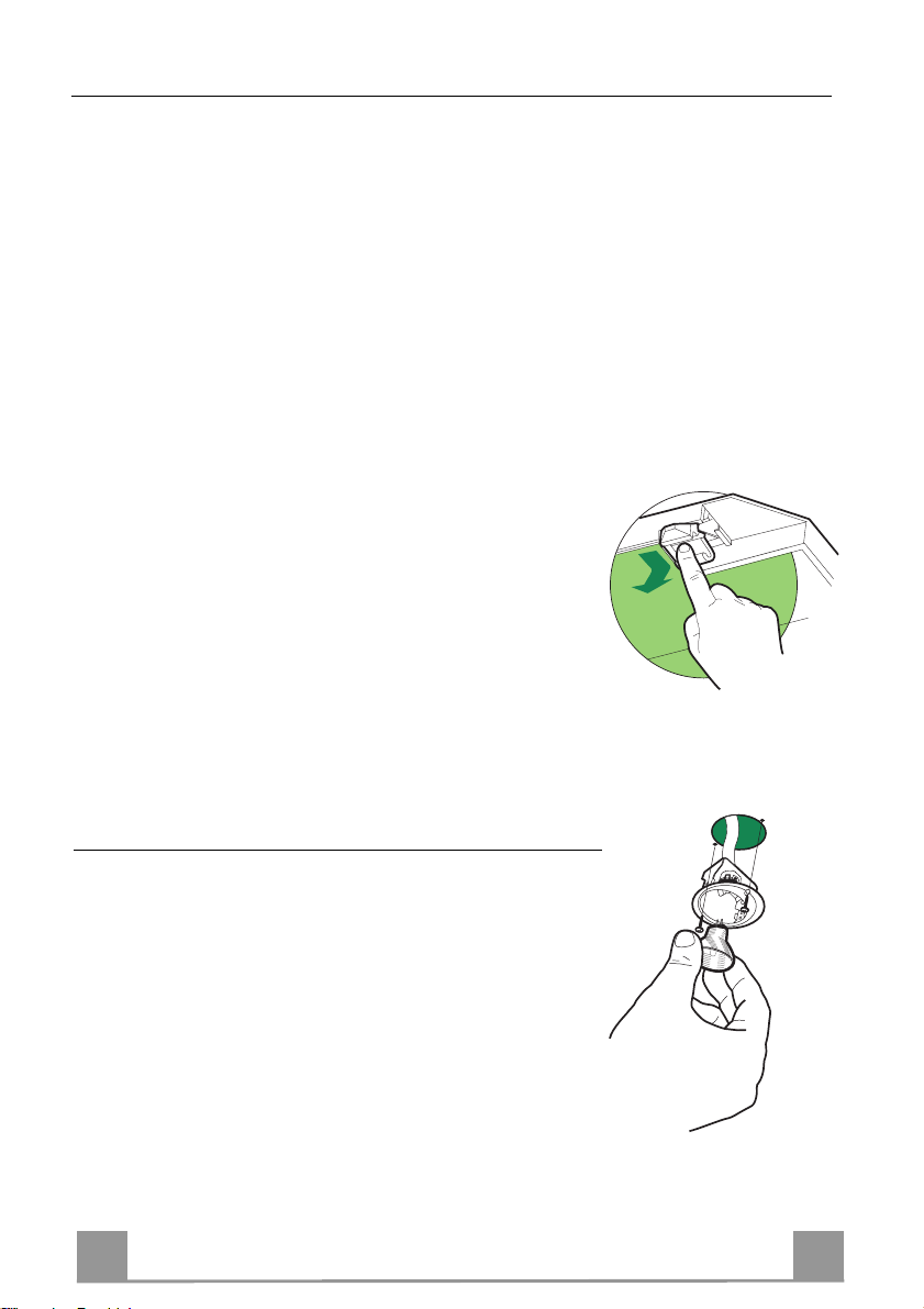
Replace the Filter
• Remove the metal grease filters.
• Remove the saturated charcoal filter, turn ing the fasteners p rovided.
• Fit the new filter and fasten it its correct position.
• Put the metal grease filters in their seats.
Lighting
LIGHT REPLACEMENT
20 W halogen light.
• Remove the 2 screws fixing the Lighting support, and pull it
out of from the Hood.
• Extract the lamp from the Support.
• Replace with another of the same type, making sure that the
two pins are properly inserted in the lamp holder socket holes.
• Rep lace the Support, fixing it in place with the two screws removed as above.
Page 18
FR 118
CONSEILS ET SUGGESTIONS
650 mm min.
La présente notice d'emploi vaut pour plusieurs versions de l'appareil. Elle
peut contenir des de scriptions d'acce ssoires ne figuran t pas dans votre appareil.
INSTALLATION
• Le fabricant décline toute responsabilité en cas de dommage dû à une installation non corr ecte ou non conforme aux rè gles de l’art.
• La distance minimale de sécurité entre le plan de cuisson et la hotte doit être
de 650 mm au moins.
• Vérifier que la tension du secteur correspond à la valeur qui figure sur la plaquette apposée à l’intérieur de la hotte.
• Pour les Appareil s appartenant à la I
mise à la te rre de l’installation électrique domestiqu e ait été effectuée confor-
mément aux normes en vigueur.
• Connecter la hotte à la sortie d’air aspiré à l’aide d’une tuyauterie
d’un diamètre égal ou supérieur à 120 mm. Le parcour s de la
tuyauterie doit être le pl us court possible.
• Eviter de connecter la hotte à des conduites d’évacuation de fumées
issues d’un e combustion tel que (Chaudière, cheminée, etc…).
• Si vous utilisez des appareils qui ne fonctionnent pas à l’électricité
dans la pièc e ou est installée la hotte (par exemple: des appareil s
fonctionnant au gaz), vous devez prévoir une aération suffisante du milieu. Si
la cuisine en est dépourvue, pratiquez une ouverture qui communique avec
l’extérieur pour garantir l’infiltration de l’air pur.
UTILISATION
• La hotte a été conçue exclusivement pour l’usage domestique, dans le but
d’éliminer les odeurs de l a cuisine.
• Ne jamais utiliser abusivement la hotte.
• Ne pa s laisser les flammes libres à forte intensité quand la ho tte est en service.
• Toujours régler les flammes de manière à éviter toute sortie latérale
de ces derni ères par rapp ort au fond des marmites.
• Contrôler les friteuses lors de l’utilisation car l’huile surchauffée
pourrait s’enflammer.
• Ne pas préparer d’aliments flambés sous la hotte de cuisine : risque d’ incendie
• Cet appareil ne d oit pa s être utilisé pa r des personn es (y comp ris le s en fants)
ayant des capacités psych iques, sen sorielles ou mentale s réduites, ni pa r des
personnes n’ayant pas l’expérience et la connaissance de ce type d’appareils,
à moins d'être sous le contrôle et la formation de personnes responsables de
leur sécurité.
• Les enfants doivent être surveillés pour s'assurer qu'ils ne jouent pas avec
l'appareil.
ENTRETIEN
• Avant de procéder à toute opération d’entretien, retirer la hotte en retirant la
fiche ou en actionnant l’interrupteur général.
• Effectuer un entretien scrupuleux et en temps dû des Filtres, à la cadence
conseillée.
• Pour le nettoyage des surfaces de la hotte , il suffit d’u tiliser un ch iffon humide
et détersif liquide neutre.
ère
Classe, veiller à ce que la
Page 19
FR 119
CARACTERISTIQUES
Encombrement
650 min.
Page 20
FR 220
Composants
Réf. Q.té Composants de Produit
1 1 Corps Hotte équipé de: Comandes, Lumière, Filtres
2 1 Cheminée Télescopique formée de :
2.1 1 Cheminée Supérieure
2.2 1 Cheminée Inf érieure
7.1 1 Treillis télescopique avec Aspirateur, formé par:
7.1a 1 Treillis supérieur
7.1b 1 Treillis inférieur
9 1 Flasque de Réduction ø 150- 1 2 0 mm
10 1 Flasque ø 150
10a 1 Buse avec c lapet ø 150
15 1 Raccord Sortie Air
24 1 Boîte connexions
25 2 Colliers de serrage serre-tube
Réf. Q.té Composants pour l’installation
11 4 Chevilles ø 10
12c 6 Vis 2,9 x 6,5
12e 2 Vis 2,9 x 9,5
12f 4 Vis M6 x 10
12g 4 Vis M6 x 80
12h 4 Vis 5,2 x 70
21 1 Gabarit de p erçage
22 4 Rondelles øi 6,4
23 4 Écrous M6
Q.té Documentation
1 Manuel d’instructions
7.1
21
22
12c
2
12c
1
7.1a
12g
7.1b
2.1
2.2
23
12c
25
12e
11
12h
15
10
9
10a
24
12f
Page 21

FR 221
INSTALLATION
Perçage Plafond/Étagère et Fixation Treillis
PERÇAGE PLAFOND/ETAGERE
• À l’aide d’un Fil à plomb, reporter sur le Plafond/Étagère de support le centre du Plan de
Cuisson.
• Poser contre le Plafond/Étagère le Gabarit de Perçage 21 fourni avec l’appareil, en faisant
coïncider son centre avec le centre projeté et en alignant les ax es du Gabarit avec les axes du
Plan de Cuisson.
• Marquer les centres des Trous du Gabarit.
• Percer les trous qui ont été marqués:
• Plafond en Béton massif: en fonction des Goujons pour Béton utilisés.
• Plafond en Briques avec chambre à air, avec épaisseu r résistant e de 20 mm: ø 10 mm (in-
sérer immédiatement les Chevilles 11 fournies avec l’appareil).
• Plafond en Poutrage en Bois: en fonction des Vis à Bois utilisées.
• Étagère en Bois: ø 7 mm.
• Passage du Câble électrique d’Alimentation: ø 10 mm.
• Sortie Air (Version Aspirante): en fonction du diamètre de la connexion avec les Tuyaux
d’Évacuation Externe.
• Visser deux vis en les croisant et en laissant 4-5 mm. de distance par rapport au plafond:
• pour le Béton massif, des Goujons pour Béton, non fournis avec l’appareil.
• pour Briques percées, ayant u ne épaisseur résistante de 20 mm. en viron, utiliser les Vis
12h, fournies avec l'appareil.
• pour le Poutrage en bois, 4 Vis à bois, non fournies avec l’appareil.
• pour l’Étagère en Bois, 4 Vis 12g avec Rondelles 22 et Écrous 23, fournis avec l’appareil.
Page 22

FR 222
FiXATION TREILLIS
2
2
1
1
• Dévisser les deux vis qui fixent la cheminée inférieure et sortir
cette dernière du treillis (depuis la partie inférieure).
• Dévisser les deux vis qui fixent la cheminée supérieure et sortir
cette dernière du treillis (depuis la partie supérieure).
Si l’on souhaite régler la hauteur du treillis, effectuer les opérations suivantes:
• Dévisser l es huit vis métriques qui un issent les deux colonnes,
qui se trouvent sur les côtés du treillis.
• Régler la hauteur souhaitée du treillis et revisser les vis qui ont
été précédemment retirées.
• Insérer la cheminée supérieure depuis le haut et la laisser libre
sur le treillis.
• Soulever le treillis, encastrer les oeillets sur les vis et faire coulisser jusqu’à la butée;
• Serrer les deux vis et visser les autres deux vis fournies avec
l’appareil;
Avant de serrer définitivement les vis, il est possible d’effectuer
des réglages, en dépl açant le tr eillis, tou t en cont rôlan t qu e les vis
ne sortent pas du logement de l’œillet de réglage.
• La fixation du Treillis doit être solide, en fonction du poids de
la Hotte et des contraintes provoquées par les poussées latérales occasionnelles auxquelles l’Appareil monté sera soumis.
Après avoir effectué la fixation, vérifier que la base soit stable,
même si le Treillis est soumis à des contraintes de flexion.
• Dans tous les cas où le Plafond ne devait pas être suffisamment
robuste en correspondance du point d’accrochage, l’Installateur
devra se charger de le rendre plus solide au moyen de plaques
et contre-plaques spéciales, ancrées sur les parties structuralement résistantes.
Page 23

FR 223
Branchements
ø 120
25
9
10a
10a
ø 150
25
15
10
SORTIE AIR VERSION ASPIRANTE
En cas d’installation en version aspirante, brancher la hotte à la
tuyauterie de sortie via un tube rigide ou flexible de ø 150 ou 120
mm, au choix de l’installateur.
Branchement avec un tube de ø150
• Insérer la buse avec clapet 10a.
• Fixer le tube par des colliers appropriés. Le matériau nécessaire n’est pas fourni.
Branchement avec un tube de ø120
• Insérer le flasque de réduction 9 sur la buse avec clapet 10a.
• Fixer le tube par des colliers appropriés. Le matériau nécessaire n’est pas fourni.
• Retirer les éventuels filtres anti-odeur au charbon actif.
Sortie air version Filtrante
• Fixer le raccord 15 au Treillis à l’aide des 4 Vis fournies avec
l’appareil.
• Bloquer la bride 10 dans le trou inférieur de le raccord 15.
• Joindre la sortie d ’air de la hotte avec la bride placée sou s la
rallonge par un tuyau rigide ou flexible ø 150 ( le choix est de
l’installateur).
Page 24

FR 224
Montage Cheminée - Montage Corps Hotte
12f
12c
12c
24
12e
Cmd
12c
Lux
• Positionner la Cheminée supérieure et fixer cette dernière dans
la partie supérieure du Treillis à l’aide de 2 Vis 12c (2,9 x 6,5)
fournies avec l’appareil.
• De la même façon, positionner la Cheminée inférieure et fixer
cette dernière dans la partie inférieure du Treillis à l’aide de 2
Vis 12c (2,9 x 6,5) fournies avec l’appareil.
Avant de fixer le Corps de la Hotte au Treillis:
• Retirer les Filtres anti-graisse du Corps de la Hotte.
• Retirer les éventuels Filtres Anti-odeur au Charbon actif.
• Ensuite, fixer par le bas, au moyen de 4 Vis 12f (M6 x 10)
fournies avec l’appareil, le Corps de la Hotte au Treillis prévu.
BRANCHEMENT ELECTRIQUE
• Brancher la hotte sur le secteur en interpo sant un interrupteur
bipolaire avec ouvertu re des contacts d’au moins 3 mm.
• Enlever les filtres à graisse (voir "Entretien") et s'assurer que le
connecteur du câble d'alimentation soit bien branché dans la
prise du diffuseur.
• Connecter le Connecteur des Commandes Cmd.
• Connecter le Connecteur de l’Eclairage Lux.
• Ranger les Connecteurs dans la Boîte de protection 24 en la
fermant à l’aide des 2 Vis 12e (2,9 x 9,5) fournies avec
l’appareil.
• Fixer la Boîte de protection au Corps de la Hotte à l’aide des 2
Vis 12c (2,9 x 6,5) fournies avec l’appareil.
• Pour la Version Filtrante, monter le Filtre Anti-odeur au Charbon actif.
• Remonter les Filtres Anti-graisse.
Page 25

FR 225
UTILISATION
L T1 T2 T3 T4 T5 F
Il est possible d’allumer la hotte directement à la vitesse demandée en pressant la touche
sans devoir d’abord utiliser la touche 0/1.
Touche
Fonction base
Témoins lumineux
Double fonction
Appuyer brièv ement sur cette touche pour allumer et
L
éteindre les lumières.
Appuyer sur cette touche pendant 2 secondes
pour allumer les lumières en mode « lumièr e de
courtoisie » La puissanc e des lampes est alors
réduite à envi ron 5W. Cette fonction peut être
désactivée en appuyant à n ouveau brièvement
sur la touche pour passer au mode normal
d’éclairage. Dans ce mode d’ éclairage de courtoisie, la touche n’est pas allumée.
Eteint le moteur fonctionnant à n’importe quelle vi-
T1
tesse
Fait fonctionner le moteur en première vitesse
T2
Appuyer brièv ement pour faire fonctionner le moteur
T3
en deuxième vites s e
Appuyer sur cette touche pendant env. 2 secondes pour d éclencher la fonction “Retard”, c-àd. l’arrêt retardé de l’app areil. Utile pour achever
d’éliminer toute odeur rés iduelle. Peut être activée depuis la position « Arr êt » ou les vitesses
1,2,3 ; pour dés activer cette fonction, i l suffit
d’appuyer sur n’importe quelle touche (T), sauf la
T3. Le Retard prend effet selon les modalités
suivantes:
1° vitesse / arrêt (OFF) = 20 minut es
2°vitesse = 15 minutes
3°vitesse = 5 minutes
Fait fonctionner le moteur en troisième vitesse
T4
Voyant éteint Lumières éteintes
Voyant allumé Lumières allumées
Voyant éteint Lumière de courtoisie
Voyant allumé Moteur actif
Voyant éteint Moteur inactif
Voyant allumé Deuxième vitesse active
Voyant cligno-
tant
allumée
Voyant allumé
Fonction Retar d
Active
Voyant allumé
Page 26

FR 226
Touche
T5
F
Fonction base
Fait fonctionner le moteur en vitesse intensive
pendant 5 minut es. Après 5 minutes, l’appareil
retourne à la v itesse choisie auparavant. Si la
mise en marche es t effectuée quand l’app areil est
éteint, après 5 minutes le système retourne à la
première vitesse.
Appuyer sur cette touche pendant 4 secondes
pour rétabli r le signal d’alarme des f iltres, le témoin lumineux T1 clignotera. Cette procédure
peut être eff ectuée seule m ent quand le moteur
est éteint.
Témoins lumineux
Voyant allumé
Voyant allumé Signale que les Filtres à
Voyant clignotant
Graisse Métalliques sont saturés et qu’il est temps de les
laver. L’alarme se déclenche
après 100 heures de foncti onnement effectif de la Hotte.
Quand il est ac tivé, l’alarme
signale que le Filtre anti-odeur
au charbon actif doit être remplacé ; les Filtres à Graisse
Métalliques doivent égal ement
être lavés. L’alarme indiquant
la saturation des Filtres Antiodeur au charbon actif s e déclenche après 200 de fonct ionnement effectif de la Hotte.
(Pour la mise en marche voir
leparagraphe Filtre anti-odeur)
Page 27

FR 227
ENTRETIEN
TELECOMMANDE (FOURNIE SUR DEMANDE)
Il est possible de commander cet appareil au moyen d’une télécommande, alimentée avec des piles alcalines zinc-charbon 1,5 V
du type standard LR03-AAA.
• Ne pas ranger la télécommande à proximité de sources de chaleur.
• Ne pas jeter les piles; il faut les déposer dans les récipients de
récolte spécialement prévus à cet effet.
Filtres à graisse
NETTOYAGE FILTRES A GRAISSE METALLIQUES
Rétablissement du signal d’alarme
• Éteindre le Moteur d’aspiration.
• Appuyer sur la touche F pendant au moins 4 secondes, jusqu’à
ce que le voyant T1 clignote pour confirmer la mise en marche.
Nettoyage Filtres
• Ils sont lavables même en lave-vaisselle et doivent être lavés
environ tous les 2 mois ou plus souvent, en cas d’utilisation
particulièrement intensive.
• Retirer les Filtres, un à un, en les poussant vers la partie postérieure du groupe tout en tirant vers le bas.
• Laver les Filtres en évitant de les plier, et les faire sécher avant
de les remonter.
• Remonter les Filtres en faisant attention de tenir la poignée
vers la partie externe visible.
Page 28

FR 228
Filtre anti-odeur (Version Filtrante)
Il ne peut être ni lavé ni récupéré, il faut le changer quand la touche F clignote ou au moins
tous les 4 mois. L’alarme fonctionne seulement quand le Moteur d’aspiration est en marche
Activation/Désa cti vation du signal d’alarme
• Pour les Hottes en Version Filtrante, l’alarme indiquant la saturation des Filtres doit être activée au moment de l’installation ou ultérieurement.
• Éteindre les lumières et le Moteur d’asp i ration.
• Débrancher la Hotte en retirant la prise du groupe moteur ou en éteignant l’Interrupteur bipolaire de la hotte ou du réseau électrique.
• Rétablir le branchement en appuyant sur la touche T2.
• Relâcher la touche, les touches L, T2 et F s’allument sans clignoter.
• Dans les 3 secondes qui suivent, appuyer sur la touche F jusqu’à ce qu’elle clignote pour
confirmer la mise en marche :
• Le voyant clignote deux fois : MISE EN MARCHE alarme saturatio n Filtre anti-odeur au
Charbon
• Le voyant clignote une fois : EXTINCTION alarme saturation Filtre anti-odeur au Char-
bon
REMPLACEMENT FILTRE ANTI- ODEUR AU CHAR BON ACTIF
Rétablissement du signal d’alarme
• Éteindre le Moteur d’aspiration.
• Appuyer sur la touche F pendant au moins 4 secondes, jusqu’à
ce que le voyant T1 clignote pour confirmer la mise en marche.
Changement du Filtre
• Retirer les Filtres à graisse métalliques.
• Retirer le Filtre anti-odeur au Charbon actif saturé en agissant
sur les crochets qui le tiennent en place.
• Mettre le nouveau Filtre en l’accrochant bien en place.
• Remonter les Filtres à graisse métalliques.
Eclairage
REMPLACEMENT LAMPES
Lampe halogène de 20 W.
• Retirer les 2 Vis qui fixent le Support éclairage et ôter ce d ernier de la Hotte.
• Extraire la Lampe du Support.
• Re mplacer par un e nouvelle lampe possédant les mêmes caractéristiques, en veillant à ce que les deux fiches soient correctement insérées dans le logement de la Douille.
• Remonter le Support en le fixant à l’aide des deux Vis précédemment retirées.
Page 29

DE 229
EMPFEHLUNGEN UND HINWEISE
650 mm min.
Diese Gebrauchsanleitung gilt für mehrere Geräte-Ausführungen. Es ist mög-
lich, dass einzelne Ausstattungsmerkmale beschrieben sind, die nicht auf Ihr
Gerät zutreffen.
MONTAGE
• Der Hersteller haftet nicht für Schäden, die auf eine fehlerhafte und unsachgemäße Montage zurückzuführen sind.
• De r minimale Sicherhei tsabstand zwischen Ko chmulde und Haube mu ss 650
mm betragen.
• Prüfen, ob die Netzspannung mit dem Wert auf dem im Haubeninneren angebrachten Schild üb er ei ns ti mmt.
• Bei Geräten der Klasse I ist sicherzustellen, dass die elektrische Anlage des
Wohnhauses über eine vorschriftsmäßige Erdung verfügt.
• Das Anschlussrohr der Haube zur Luftaustrittsöffnung muss einen Durchmesser von 120 mm oder darüber aufweisen. Der Rohrverlauf muss so kurz wie
möglich sein.
• Die Haube darf an keine Entlüftungsschächte ange schlossen werden, in die
Verbrennungsgase (Heizkessel, Kamine usw.) geleit et werden.
• Werden im Raum außer der Dunstabzugshaube andere, nicht elektrisch betriebene (z.B. gasbetrie bene) Geräte verwendet, mu ss für eine ausreichende
Belüftung gesorgt werden. Sollte die Küche diesbezüglich nicht entsprechen,
ist an einer Aussenwand eine Öffnung anzubringen, die Frischluftzufuhr gewährleistet.
BEDIENUNG
• Die Dunstabzugshaube ist aussch ließlich zum Einsatz im privaten Haushalt
und zur Beseitigung von Küchengerüchen vorgesehen.
• Unsachgemäßer Einsatz der H aube ist zu unterlassen.
• Große Flammen bei eingeschalteter Haube ni emals unbedeckt lassen.
• Die Intensivität der Flamme ist so zu regulieren, dass sie den Topfboden nicht
überragt.
• Frittiergeräte müssen während des Gebrauchs stets beaufsichtigt werden:
überhitztes Öl kann sich entzünden.
• Keine flambierten Speisen u nter der Abzu gshaube zubereiten: Brandgefahr.
• Dieses Gerät darf n icht von Person en, auch Kind ern, m it verm inderte n psych ischen, sensorischen und geistigern Fähigkeiten, oder von Personen ohne Erfahrung und Kenntnisse benutzt werden, sofern sie nicht von für ihre Sicherheit verantwortlichen Personen beaufsichtigt und beim Gebrauch des Geräts
angeleitet werden.
• Kinder dürfen sich ni cht unbeau fsichtigt in der Nähe des Ge räts aufha lten und
auf keinen Fall mit dem Gerät spielen.
WARTUNG
• Bevor Wartungsarbeiten durchgeführt werden, muss die Stromzufuhr zur Haube unterbrochen werden, indem der Stecker gezogen oder der Hauptschalter
abgeschaltet wird.
• Bei der Filterwartung müssen die vom Hersteller empfohlenen Zeiträume zum
Austauschen der Filter genauestens eingehalten werden.
• Zur Reinigung der Haubenflächen Wir empfehlen ein feuchtes Tuch und ein
mildes Flüss igreinigungsmittel.
Page 30

DE 330
CHARAKTERISTIKEN
Platzbedarf
650 min.
Page 31

DE
331
Komponenten
Pos. St. Produktkomponenten
1 1 Haubenkörper mit Schaltern,
2 1 Teleskopkamin bestehend aus:
2.1 1 oberer Kaminteil
2.2 1 unterer Kaminteil
7.1 1 Teleskopgerüst komplet t mit Gebläse, bestehend aus:
7.1a 1 oberer Gerüstteil
7.1b 1 unterer Gerüstteil
9 1 Reduzierflansch ø 150-1 20 mm
10 1 Flansch ø 150
10a 1 Flansch mit Ruckstauklappe ø 150
15 1 Luftaustritt-Anschlussstück
24 1 Verbindungsdose
25 2 Rohrschellen
Pos. St. Montagekomponenten
11 4 Bügel ø 10
12c 6 Schrauben 2,9 x 6,5
12e 2 Schrauben 2,9 x 9,5
12f 4 Schrauben M6 x 10
12g 4 Schrauben M6 x 80
12h 4 Schrauben 5,2 x 70
21 1 Bohrschablone
22 4 Unterlegscheiben ø 6,4
23 4 Schraubenmuttern M6
St. Dokumentation
1 Bedienungsanleitung
7.1
21
22
12c
2
12c
1
7.1a
12g
7.1b
2.1
2.2
23
12c
25
12e
11
12h
15
10
9
10a
24
12f
Page 32

DE 332
MONTAGE
Bohren der Decke/Trägerplatte und Montage des Teleskopgerüsts
BOHREN DER DECKE/TRAGERPLATTE
• Mit Hilfe eines Lots den Kochmulden-Mittelpunkt an der Decke oder Trägerplatte ermitteln
und kennzeichnen.
• Die mitgelieferte Bohrschablone 21 so auf die Decke/Trägerplatte legen, dass die Schablo nenmitte mit dem gekennzeichneten Mittelpunkt übereinstimmt und die Schablonenseiten
auf die Seiten der Kochmulde ausrichten.
• Die Mitte der Schablonenbohrungen kennzeichnen.
• Die gekennzeichneten Punkte bohren:
• Massivbeton-Decke: je nach verwendeten Beton-Dübeln.
• Decke aus Hohlkammer-Ziegeln mit 20 mm Wandungsstärke: ø 10 mm (sofort die mitge-
lieferten Dübel 11 einfügen).
• Holzbalkendecke: je nach verwendeten Holzschrauben.
• Holz-Trägerplatte: ø 7 mm.
• Durchgang für das Speisekabel: ø 10 mm.
• Luftaustritt (Abluftversion): je nach Durchmesser des Anschlussrohres für die Luftablei-
tung.
• Zwei sich gegenüberliege nde Sc hr a ube n festziehen und 4-5 mm Fre ira um z ur De ck e be las se n:
• bei Massiv-Betondecken mit speziellen Betondübeln, die nicht mitgeliefert werden;
• für Hohlkammer-Ziegeln mit ca. 20 mm Wandungsstärke die mitgelieferten Schrauben
12h verwenden;
• bei Holzbalken-Decken mit 4 Holzschrauben, die nicht mitgeliefert werden;
• bei Holz-Trägerplatten mit 4 Schrauben 12g, Unterlegscheiben 22 und Schraubenmuttern
23, die im Lieferumfang enthalten sind.
Page 33

DE 333
Montage des Teleskopgerüsts
2
2
1
1
• Die beiden Schrauben lösen, die den unteren Gerüstteil fixieren
und diesen aus dem Gerüst ziehen (an der Unterseite)
• Die beiden Schrauben lösen, die den oberen Gerüstteil fixieren
und diesen aus dem Gerüst ziehen (an d er Oberseit e).
Für eine eventuelle Regulierung der Gerüsthöhe folgendermaßen
vorgehen:
• Die acht Stellschrauben an den Gerüstseiten, die die beiden
Säulen vereinen, lösen.
• Den oberen Gerüstteil von oben einfügen und frei auf dem Gerüst lassen.
• Das Gerüst heben, die Langlöcher bei den Schrauben einrasten
und bis zum Anschlag laufen lassen;
• Die beiden Schrauben festziehen und die beiden anderen mitgelieferten Schrauben einschrauben;
Bevor die Schrauben definitiv festgezogen werden, kann eine
Regelung durch Bewegen des Gerüstes erfolgen, wobei darauf zu
achten ist, dass die Schrauben nicht aus dem Sitz des Regellangloches austreten.
• Wir verweisen auf die Notwendigkeit einer absolut sicheren
Befestigung des Teleskopgerüsts, die sowohl dem Eigengewicht der Haube wie auch dem seitlichen Druck, der auf das
Gerät einwirken kann , entsprechen muss. Nach erfol gter Montage ist zu prüfen, ob das Teleskopgerüst auch bei Biegebeanspruchung stabil ist.
• Sollte die Decke am Befestigungspunkt nicht robust genug
sein, muss der Installateur geeignete Platten und Gegenplatten
verwenden, die an strukturell widerstandsfähigen Teilen verankert werden.
Page 34

DE 334
Anschlüsse
ø 120
25
9
10a
10a
ø 150
25
15
10
ANSCHLUSS IN ABLUFTVERSION
Bei Abluftbetrieb kann die Haube vom Installateur wahlweise
mittels Rohr oder Schlauch (ø150 oder 120mm) an die Außenrohrleitung angeschlossen werden.
Anschlussrohres ø 150
• Den Flansch mit Ruckstauklappe 10a anbringen.
• Das Rohr mit geeignet en Rohrschellen fixieren.Das hi erzu erforderliche Material wird nicht mitgeliefert.
Anschlussrohres ø 120
• Bei Verwendung eines Anschlussrohres ø 120 den Reduzierflansch 9 am Flansch mit Ruckstauklappe 10a anbringen.
• Das Rohr mit geeignet en Rohrschellen fixieren.Das hi erzu erforderliche Material wird nicht mitgeliefert.
• Eventuell vorhandene Aktivkohlefilter entnehmen.
Anschluss in Umluftversion
• Der Anschluß 15 an das Teleskopgerüst mit den 4 beiliegenden
Schrauben befestigen.
• Den Flansch 10 an die untere Bohrung des Anschluß 15 an-
bringen.
• Den Haubenluftaustritt mit Hilfe eines Rohres oder Schlauches
Ø 150 (die Wahl bleibt dem Installateur überlassen) mit dem
Flansch, der sich unter dem Umlenkteil befindet, verbinden.
Page 35

DE 335
Kaminmontage und Montage des Haubenkörpers
12f
12c
12c
24
12e
Cmd
12c
Lux
• Den oberen Kaminteil positionieren und beim oberen Gerüstteil mit Hilfe der 2 mitgelieferten Schrauben 12c (2,9 x 6,5) fixieren.
• Gleichermaßen den unteren Kaminteil positionieren und beim
unteren Gerüstteil mit Hilfe der 2 mitgelieferten Schrauben 12c
(2,9 x 6,5) fixieren.
Vor der Montage des Haubenkörpers am Teleskopgerüst:
• Die Fettfilter entnehmen.
• Eventuell vorhandene Aktivkohle-Geruchsfilter entnehmen.
• Dann den Haubenkörper mit Hilfe der 4 mitgelieferten Schrauben 12f (M6 x 10) von unten her am Teleskopgerüst fixieren.
ELEKTROANSCHLUSS
• Bei Anschluss der Haube an das Stromn etz muss ein zweipoliger Schalter mit einem Öffnungsweg von mindestens 3 mm
zwischengeschaltet werden.
• Entfernen Sie die Fettfilter (s. Abschnitt „Wartung“) und versichern Sie sich, daß di e Kabelverbindung in die Steckd ose des
Gebläses einwandfrei eingesteckt wird.
• Den Verbinder der Steuerungen Cmd anschlie- ßen.
• Den Verbinder der Beleuchtung Lux anschließen.
• Den Verbinder wieder in die Verbindungsdose 24 stecken und
diese mit den 2 mitgelieferten Schrau-ben 12e (2,9 x 9,5) verschließen.
• Die Verbindungsdose mit den 2 beiliegenden Schrauben 12c
(2,9 x 6,5) am Haubenkörper fixieren.
• Bei Umluftbetrieb den Aktivkohle-Geruchsfilter montieren.
• Die Fettfilter wieder montieren.
Page 36

DE 336
BEDIENUNG
L T1 T2 T3 T4 T5 F
Die Haube kann direkt auf die gewünschte Stufe eingeschaltet werden ohne daß man vorher
auf die Gebläsetaste 0/1 drückt.
Grundfunktion
Taste
Doppelfunktion
Ein kurzer Tas tendruck schaltet die Bel euchtungsanlage
L
ein und aus.
Wird die Taste 2 Sekunden lang gedrückt, schaltet sich
die “Nachtbeleuchtung” ein. Die Lampen werde n mit
einer verringerten Leistung von cirka 5W gespeist. Diese Funktion kann deakti viert werden , indem die Taste 2
Sekunden lang gedrückt wird bzw. kurz gedrückt wird,
um auf den normalen Beleuchtungsmodus überzugehen. Im Modus „Nachtbeleuchtung“ leuchtet die Taste
nicht auf.
Schaltet den Motor unabhängig von der Gebläsestuf e ab
T1
Aktiviert den Motor mit der ersten Gebläsestufe
T2
Bei kurzem Drüc ken dieser T aste wird der Mot or mit der
T3
zweiten Gebläsestufe aktiviert
Wird die Tast e cirka 2 Sekun den lang gedrückt, akti viert
sich die Funkt ion Delay, d.h. die verzögerte Abschaltung des Gerätes. Eignet sich zur kompletten Beseitigung von Rest gerüchen. Kann in der Position OFF und
den Gebläses tufen 1, 2, 3 aktiviert werd en; kann vorzeitig durch Drüc ken jeder beliebigen Taste (T) (mit Aus-
nahme der Tas te T3) deaktiviert werden. Die DelayFunktion erfolgt nach nachstehendem Zeitplan:
1. Stufe / OFF = 20 Minuten
2. Stufe = 15 Minuten
3. Stufe = 5 Minuten
Aktiviert den Motor mit der dr itten Gebläsestufe
T4
Taste erloschen
Taste leuchtet auf
Taste erloschen
Taste leuchtet auf
Taste erloschen
Taste leuchtet auf
Taste blinkt Delay-Funkt ion ak t iv ier t
Leuchtsignale
Beleuchtung abgeschalt et
Beleuchtung eingeschal tet
Nachtbeleuc ht ung ei n geschaltet
Motor aktiviert
Motor deaktivi ert
Taste leuchtet auf
Zweite Gebläsestufe aktiviert
Taste leuchtet auf
Page 37

DE 337
Taste
T5
Grundfunktion
Aktiviert den Motor mit der 5 Minuten dauernden Intensivstufe. Nach Ablauf der 5 Min uten läuft das Gerät wieder
mit der zuvor eingestellten Sauggeschwindigkeit. Wird
diese Funktion bei ab ges c hal tetem Gerät aktiv ier t, wird
nach Ablauf der 5 Minute n auf die ers te Gebläsestufe
übergegangen.
Wird die Taste 4 Sekunden lang gedrückt , erfolgt die
F
Rückstellung des Filteralarms, der durch Blinken der Taste T1 angezeigt wird. Dieses Ver fahren kann nur bei abgeschaltete m Motor durchg eführt werden.
Leuchtsignale
Taste leuchtet auf
Taste leuchtet auf
Taste blinkt Sättigungsanzeige der Ak-
Sättigungsanzeige der M etallfettfilter, die gewaschen
werden müssen. Der Alarm
erfolgt nach 100 effektiven
Arbeitsstund en der Ha ube.
tivkohle-Geruchsfilter , falls
diese aktiv iert wurde; die
Filter sind auszutauschen;
die Metallfettfilter müssen
ebenfalls gewaschen werden. Die Sättigungsanzeige
des AktivkohleGeruchsfilters erfolgt nach
200 effektiven Arbeitsstunden der Haube. (Aktivierung
siehe Abschn.
Geruchsfilter)
Page 38

DE 338
WARTUNG
FERNBEDIENUNG (OPTION)
Dieses Gerät kann mit einer Fernbedienung gesteuert werden,
welche mit alkalischen Zink-Kohle-Batterien 1,5 V des Standardtyps LR03-AAA versorgt wird.
• Die Fernbedienung nicht in die Nähe von Hitzequellen legen.
• Batterien müssen vorschriftsmäßig entsorgt werden.
Fettfilter
REINIGUNG DER SELBSTTRAGENDEN METALLFETTFILTER
Rückstellen der Sättigungs anzeige
• Den Gebläsemotor abschalten.
• Die Taste F mindestens 4 Sekunden lang drücken, bis die Taste
T1 als Bestätigung zu blinken beginnt.
Filterreinigung
• Die Filter können auch im Geschirrspüler gereinigt werden und
sollten cirka alle 2 Monate - bzw. bei sehr intensivem Einsatz
auch häufiger - gereinigt werden.
• Die Filter einzeln entnehmen, indem sie zur Rückseite der
Gruppe geschoben und gleichzeitig nach unten gezogen werden.
• Die Filter waschen, darauf achten, sie nicht zu verbiegen und
vor der Remontage trocknen lassen.
• Bei der Remontage darauf achten, dass sich der Griff an der
sichtbaren Außenseite befindet.
Page 39

DE 339
Geruchsfilter (Umluftbetrieb)
Dieser Filter ist weder wasch- noch wiederverwendbar und ist auszutauschen, wenn die Taste
F blinkt oder zumindest alle 4 Monate. Die Sättigungsanzeige erfolgt nur, wenn der Gebläsemotor eingeschaltet ist.
Aktivierung/Deaktivierungder S ättigungsa nzeige
• Bei Hauben mit Umluftbetrieb erfolgt die Aktivierung der Sättigungsanzeige bei der Installation oder später.
• Die Beleuchtung und den Gebläsemotor abschalten.
• Die Haube vom Stromnetz trennen, indem der Verbinder des Speisekabels der Motorgruppe
gezogen oder der zwischengeschaltete zweipolige Schalter oder der Hauptschalter betätigt
wird.
• Den Anschluss wieder herstellen, während die Taste T2 gedrückt gehalten wird.
• Die Taste loslassen; die Tasten L, T2 und F leuchten pausenlos auf.
• Innerhalb v o n 3 Sekunden die Taste F solange drücken, bis sie als Bestätigung zu blinken
beginnen:
• 2-maliges Blinken – Sättigungsanzeige Aktivkohle-Geruchsfilter AKTIVIERT
• 1-maliges Blinken – Sättigungsanzeige Aktivkohle-Geruchsfilter DEAKTIVIERT
AUSTAUSCHEN DES AKTIVKOHLE-GERU CHSF IL T ER
Rückstellen der Sättigungs anzeige
• Den Gebläsemotor abschalten.
• Die Taste F mindestens 4 Sekunden lang drücken, bis die Taste
T1 als Bestätigung zu blinken beginnt
Filterwechsel
• Die Metallfettfilter entfernen.
• Den gesättigten Aktivkohle-Geruchsfilter anhand der entsprechenden Anhakvorrichtungen demontieren.
• Den neuen Filter montieren, indem er in seinem Sitz eingehakt
wird.
• Die Metallfettfilter wieder montieren.
Beleuchtung
Halogenlampe 20 W
• Vor dem Auswechseln der Lampen, die beiden Schrauben der
Lampenhalterung loesen und die Lampenhalterung aus der
Dunstabzugshaube ziehen.
• Die Lampe aus der Halterung nehmen.
• Die Lampe durch eine gleichwertige ersetzen und bei der Remontage darauf achten, daß die beiden Steckerstifte vorschriftsmäßig in die Lampenfassung eingeführt werden.
• Die Lampenhalterung wieder montieren, indem die beiden zuvor entfernten Schraub en wieder angezogen werden.
AUSWECHSELN DER LAMPEN
Page 40

NL 440
ADVIEZEN EN SUGGESTIES
650 mm min.
D eze gebruiksaa nwijzing geldt vo or verschillende uitvoeringen van het appa -
raat. Het is mogelijk dat er een aantal kenmerke n worden besch reven die nie t
van toepassing zijn op uw a pparaat.
INSTALLATIE
• D e fabrikant aanvaa rdt geen enkele aa nsprakelijkheid voo r schade die voo rtkomt uit onjuiste of niet overeenkomstig de regels der kunst uitgevoerde installaties.
• De minimale veiligheidsafstand tussen de kookplaat en de wasemkap bedraagt 650 mm.
• Contro leer of de netspan ning correspondeert met de spanning d ie aangegeven is op het pl aatje aan de bi nnenkant van de wasemkap.
• Voor apparaten van klasse I dient u zich ervan te verzekeren dat het elektriciteitsnet in uw huis over een goede aardi ng beschikt .
• Verbind de wasemkap met de luchtuitlaat door middel van een leiding met een
diameter van 120 mm of groter. De leiding moet een zo kort mogelijke route afleggen.
• Sluit de wasemkap niet aan op afvoerpijpen van rook die geproduceerd is door
verbranding ( verwarmingsketels, open haarden etc.).
• Als er in het vertrek zowel de wasemkap als apparaten die niet op elektriciteit
werken (bijvoorbeeld gasapparaten) worden gebruikt, moet ervoor worden gezorgd dat het ver trek voldoe nde geventil eerd wordt. Indien de keuken geen gat
in de buitenmuur hee ft om de aanvoer van schon e lucht te garande ren, dient
dit gemaakt te worden.
GEBRUIK
• De wasemkap is uitsluitend on tworpen voor huishoudelijk gebruik, voor het
elimineren van kookgeuren. Gebruik de kap nooit op oneigenlijke wijze.
• Laat geen hoog brandende branders onbedekt onder de wasemkap
terwijl deze in werking is.
• Regel de vlammen altij d zo dat ze niet langs de pannen omhoogkomen.
• Controleer frituurpannen tijdens het gebruik: de oververhitte olie zou vlam
kunnen vatten.
• Er mag niet onder de afzuigkap geflambeerd worden; brand gevaar
• Dit apparaat mag niet worden gebruikt door personen (inclusief kinderen) met
beperkte psychisch e, sensorische en geestelijke vermo ge n s, o f door personen
zonder ervaring en kennis, tenzij ze onder toezich t staan of worden ge ïnstrueerd over het gebruik van het apparaat door personen die verantwoordelijk zijn
voor hun veiligheid.
• Kinderen moeten worden gecontroleerd om er zeker van te zijn dat ze niet met
het apparaat spelen.
ONDERHOUD
• Alvorens onderhoudswerkzaamheden uit te voeren, moet de wasemkap uitgeschakeld worden door de stekker uit het stopcontact te halen of de hoofdschakelaar om te zetten.
• Voer het onderhoud van de filters altijd tijdig en nauwgezet uit,volgens de
aanbevolen intervallen.
• Om de oppervlakken van de kap schoon te maken is het voldoende een vochtige doek en een neutraal reinigingsmi ddel te gebruiken.
Page 41

NL 441
EIGENSCHAPPEN
Buitenafmetingen
650 min.
Page 42

NL 442
Onderdelen
Ref. Productonderdelen
1 1 Wasemkap compleet met: Bedieningen, Licht, Filters
2 1 Telescopische Sc hou w Bes t aan de ui t:
2.1 1 Bovenstuk
2.2 1 Onderstuk
7.1 1 Telescopisch frame compleet met afzuiginrichting,
bestaand uit:
7.1a 1 Bovenste frame
7.1b 1 Onderste frame
9 1 Reductieflens ø 150- 120 mm
10 1 Flens ø 150
10a 1 Toom met Klep ø 150
15 1 Verbindingsstuk Luchtuitlaat
24 1 Aansluitdoos
25 2 Leidingklemmen
Ref. Installatieonderdelen
11 4 Pluggen ø 10
12c 6 Schroeven 2,9 x 6,5
12e 2 Schroeven 2,9 x 9,5
12f 4 Schroeven M6 x 10
12g 4 Schroeven M6 x 80
12h 4 Schroeven 5,2 x 70
21 1 Boormal
22 4 Ringen øi 6,4
23 4 Moeren M6
Documentatie
1 Gebruiksaanwijzing
7.1
21
22
12c
2
12c
1
7.1a
12g
7.1b
2.1
2.2
23
12c
25
12e
11
12h
15
10
9
10a
24
12f
Page 43

NL 443
INSTALLATIE
Gaten boren in plafond/plank en bevestiging frame
GATEN BOREN IN PLAFOND/PLANK
• Teken met behulp van een looddraad op het plafond/de draagplank het midden van de kookplaat af.
• Houd de bijgeleverde boormal 21 tegen het plafond/de plank, en laat het midden hiervan
samenvallen met het afgetekende punt en lijn de assen van de boormal uit met de assen van
de kookplaat.
• Teken de middelpunten van de gaten van de boormal af.
• Boor gaten in de afgetekende punten:
• Plafond van massief beton: volgens de gebruikte betonpluggen.
• Plafond van steen met luchtkamer, met resistente dikte van 20 mm: ø 10 mm.(schuif on-
middellijk de bijgeleverde pluggen 11 in de ga te n).
• Plafond van houten balken: afhankelijk van de gebruikte houtschroeven.
• Houten planken: ø 7 mm.
• Doorvoer van de elektri sche voedingskabel: ø 10 mm.
• Luchtuitlaat (Afzuigversie): overeenkomstig de diameter van de verbinding met de af-
voerleiding naar buiten.
• Zet de twee schroeven vast in kruisvorm, maar laat een ruimte vrij van 4-5 mm tussen de
schroef en het plafond:
• voor massief beton, betonpluggen, niet bijgeleverd.
• voor bakstenen muur met luchtkamer, met een resistente dikte van ongeveer 20 mm, wor-
den de schroeven 12h bijgeleverd.
• voor houten balken, 4 houtschroeven, niet bijgeleverd.
• voor houten plank, 4 schroeven 12g met ringen 22 en moeren 23, bijgeleverd.
Page 44

NL 444
BEVESTIGING FRAME
frame aan
2
2
1
1
• Draai de twee schroeven los die het onderstuk vasthouden aan
het frame en verwijder het (langst de onderkant)
• Draai de twee schroeven los die het bovenstuk vasthouden aan
het frame en verwijder het (langst de bovenkant)
Als U de hoogte van het frame wil bijstellen, gaat als volgt te
werk:
• Draai de acht metriche schroeven los die de twee kolommen
met elkaar verbinden . Deze bevinden zich aan de zijkant van
het frame.
• Om het frame stabieler te maken, moet U de vier veiligheidsschroeven vastzetten in het laatste vrije gat.
• Til het frame op, plaats de haken over de schroeven en schuif
verder tot de schroeven blokkeren;
• Schro ef deze twee schroeven go ed aan en zet ook de andere
twee bijgeleverde schroeven vast;
Vooraleer U de schroeven definitief vastschroeft, kan U nog bijpassen door het frame rond te draaien. Let wel op dat de schroeven niet uit de bevestigingshaken schuiven.
• De bevestiging van het frame moet zowel berekend zijn op het
gewicht van de wasemkap als op de belastingen die veroorzaakt worden door eventuele stoten tegen de zijkant van het
gemonteerde apparaat. Controleer na het bevestigen van het
frame of de basis stabiel is, ook als er tegen het
wordt geduwd.
• In alle gevallen waarin het plafond niet stevig genoeg is op het
punt waar de kap wordt opgehangen, dient de installateur het
plafond te verstevigen met platen en tegenplaten die verankerd
worden aan delen met een resistente structuur.
Page 45

NL 445
Aansluitingen
ø 120
25
9
10a
10a
ø 150
25
15
10
LUCHTUITLAAT AFZUIGVERSIE
Bij installatie in afzuigversie, moet u de wasemkap met de uitlaatleiding verbinden door middel van een starre of buigzame
leiding van ø 150 of 120 mm, naar keuze van de installateur.
Leiding van ø150
• De Toom met Klep 10a worden aangebracht.
• Zet de leiding vast met geschikt leidingklemmen.
Het benodigde materiaal wordt niet bij de wasemkap geleverd.
Leiding van ø120
• Voor verbinding met een leiding van ø120 mm, moet de reductieflens 9 op de Toom met Klep 10a worden aangebracht.
• Zet de leiding vast met geschikt leidingklemmen.
Het benodigde materiaal wordt niet bij de wasemkap geleverd.
• Verwijder de eventuele geurfilters met actieve koolstof.
Luchtuitlaat Filterversie
• Bevestig verbindingsstuk 15 aan de frame met behulp van de 4
bijgeleverde schroeven.
• Zet de flens 10 vast in de daarvoor bestemde opening onderaan
het verbindingsstuk 15.
• Verbind de luchtuitlaat van de wasemkap met de flens onderaan het verbindingsstuk door middel van een onbuigbare of
flexibele leiding van ø 150 mm; naar keuze van de installateur.
Page 46

NL 446
Montage van de schouw - Montage van de Wasemkap
12f
12c
12c
24
12e
Cmd
12c
Lux
• Breng het bovenste gedeelte van de schouw in positie en zet dit
aan de bovenkant vast aan het frame met 2 van de bijgeleverde
schroeven 12c (2,9 x 6,5).
• Breng op dezelfde manier het onderste gedeelte van d e schouw
in positie en zet dit aan de onderkant vast aan het frame met 2
van de bijgeleverde schroeven 12c (2,9 x 6,5).
Alvorens de wasemkap aan h et frame te bevestigen:
• Haal de vetfilters uit de wasemkap;
• Verwijder eventuele geurfilters met actieve koolstof.
• Zet vervolgens via de onderkant de wasemkap vast aan het
frame met 4 bijgeleverde schroeven 12f (M6 x 10).
ELEKTRISCHE AANSLUITING
• Sluit de wasemkap aan op de netspanning met een tweepolige
schakelaar ertussen met een opening tussen de contacten van
tenminste 3 mm.
• Verwijder de vetfilters (zie par. "Onderhoud") en verzeker u
ervan dat de stekker van de voedingskabel goed in de contactdoos van de afzuigkap is gestoken.
• Sluit de connector van de bedieningen Cmd aan.
• Sluit de connector van de verlichting Lux aan.
• Plaats de connector in de beschermdoos 24 en sluit deze met de
2 bijgeleverde schroeven 12e (2,9 x 9,5).
• Bevestig de beschermdoos aan de wasemkap met 2 van de bijgeleverde schroeven 12c (2,9 x 6,5).
• V oor de filterversie monteert u het geurfilter met actieve koolstof.
• Zet de vetfilters weer op hun plaats.
Page 47

NL 447
GEBRUIK
L T1 T2 T3 T4 T5 F
De wasemkap kan rechtstreeks ingeschakeld worden op de gewenste snelheid, door de desbetreffende toets in te drukken zonder eerst de toets 0/1 motor te bedienen.
Basisfunctie Toets
Lichtsignalen
Dubbele Functie
Als U deze toets even indrukt , wordt de verlichting aan-
L
of uitgeschakeld.
Als U deze toets 2 seconden ingedrukt houdt, wordt
er een “beleefdheidsverlichting” aangeschakeld.
De lampen branden dan met een gereduceerd vermogen van ong eveer 5W. Deze f unctie kan w eer
uitgeschakeld worden do or de toets opnieuw gedurende 2 secon den ingedrukt te houden of door even
op de toets te dr ukken en zo over te schakelen naar
de normale lic htintensitei t. Als deze b eleefdheidsverlichting brandt, is de led uit.
Schakelt de zuigmotor uit van op elke ingestelde snelheid
T1
Activeert de zuigmotor in de eerste snelheid
T2
Als U deze toets even indrukt, activeert U de zuigmotor in
T3
de tweede snelheid
Als U deze toets ongeveer 2 ‘’ ingedrukt houdt, activeert U de Delay functie, dit staat voor een vertraagde uits chakeling va n het toestel. Deze functie is
zeer geschikt om restgeurt jes te verwijderen. De Delay functie kan geactiveerd worden als het toestel
UIT staat, of als het werkt op de 1ste, 2de of 3de
snelheid; U k an de functie v oortijdig uitschakelen
door eender welke toets (T) in te drukken, met uitzondering van toets T3. De vertraagde uitschakeling
gebeurt volgens het volgende schema:
1° snelheid / UIT = 20 minut en
2° snelheid = 15 minuten
3° snelheid = 5 minuten
Activeert de zuigmotor in de derde snelheid
T4
Led uit Lichten uit
Led brandt Lichten aan
Led uit Beleefdheidsverlichting aan
Led brandt Motor aan
Led uit Motor uit
Led brandt
Led brandt De tweede snelheid is actief
Led knippert De vertr aagde uitschake-
lingsfunct ie is actief
Led brandt
Page 48

NL 448
Toets Basisfunctie Lichtsignalen
Activeert de zuigmotor ge durende 5 minuten in
T5
de intensieve snelheid. Na afloop van d eze 5
minuten, sch akelt het toestel over op de daarvoor ingestelde snelheid. Als U de wasemkap
Led brandt
meteen instel de in de intensieve snelheid, dan
schakelt het systeem na 5 minuten over op de
eerste snelheid.
Als U deze toets gedurende 4 seconden inge-
F
drukt houdt, wordt het alarmsignaal voor de
filters hernomen en begint toets T1 te knipperen. Deze procedure is alleen mogelijk als de
zuigmotor uitgeschakeld is.
Led brandt Signaleert het alarm verzadiging
metalen vetfilters, wat inhoudt dat
deze moeten w orden schoongemaakt. Dit alar m wordt geactiveerd
na 100 effectieve werk i ngs ur en va n
de wasemkap.
Led knippert Signaleert, wanneer hij geactiveerd
wordt, het alarm verzadiging actieve
koolstoffilter, wat inho udt dat deze
filter moet worden vervan gen; ook
moeten de metalen vetfilters worden
schoongemaakt. Het alarm verzadiging actieve k oolstoffil ter wordt
geactiveerd na 20 0 effec ti ev e w erkingsuren va n de wasemkap. ( Voor
de activering van het alar m zie paragraaf Geurfil ters)
Page 49

NL 449
ONDERHOUD
AFSTANDSBEDIENING (OPTIE)
Dit apparaat kan met behulp van een afstandsbediening worden
bestuurd. Deze werkt op al kaline zinkkoolstof bat terijen van 1,5
V van het standaardtype LR03-AAA.
• Bewaar de afstandsbediening niet in de buurt van warmtebronnen.
• De batterijen mogen na gebruik niet in het milieu terechtkomen, gooi ze in de hiervoor bestemde afvalbakken.
Vetfilters
SCHOONMAAK ZELFDRAGENDE METALEN VETFILTERS
Reset van het alarmsignaal
• Schakel de motor van de wasemkap uit.
• Druk gedurende minstens 4 seconden op toets F, tot de led van
toets T1 knippert ter bevestiging.
Schoonmaken filters
• De filters moeten om de 2 maanden of, bij bijzonder intensief
gebruik, vaker gereinigd worden, en kunnen ook in de vaatwasmachine worden schoongemaakt.
• Verwijder de filters één voor één door ze naar de achterkant
van de groep te duwen en ze tergelijkertijd omlaag te trekken.
• Was de filters af zonder ze te vouwen en laat ze drogen alvorens ze weer terug te plaatsen.
• Plaats de vetfilters terug, maar zorg ervoor dat de handgreep
zichtbaar blijft.
Page 50

NL 550
Geurfilters met actieve koolstof (Filterversie)
Deze filter is niet afwasbaar en kan niet herb ruikt worden. De koolstoffilter moet vervangen
worden als toets F knippert of minstens eenmaal in de 4 maanden. Het alarmsignaal wordt alleen aangegeven als de zuigmotor actief is.
Activering/Desa c tivering van het alarmsignaal
• Bij wasemkappen met luchtcirculatie moet het alarmsignaal dat aangeeft dat de filters verzadigd zijn, geactiveerd worden op het moment van de installatie of daarna.
• Schakel de verlichting en de zuigmotor uit.
• Sluit de wasemkap van het elektriciteitsnet af door de connector van de voedingskabel uit de
motorgroep te verwijderen, of door de 2-polige schakelaar uit te schakelen die tussen de
netvoeding staat, ofwel door de hoofdschakelaar uit te schakelen.
• Sluit de wasemkap weer aan op het net door toets T2 ingedrukt te houden.
• Laat de toets los, de leds van de toetsen L, T2 en F branden nu voortdurend.
• Druk binnen 3 seconden op de toets F totdat de led gaat knipperen ter bevestiging:
• 2 maal knipperen – Alarm verzadiging geurfilter met actieve koolstof GEACTIVEERD
• 1 maal knipperen – A larm verzadiging geurfilter met ac tieve k ools tof GE DE SACTIVEERD
VERVANGING GEURFILTER MET ACTIEVE KOOLSTOF
Reset van het alarmsignaal
• Schakel de zuigmotor uit.
• Druk gedurende minstens 4 seconden op toets F, tot de led van
toets T1 knippert ter bevestiging.
Vervanging filter
• Verwijder de metalen vetfilters.
• Verwijder de verzadigde geurfilter met actieve koolstof door
de bevestigingshaakjes los te maken.
• Zet de nieuwe filter vast op zijn plaats.
• Plaats opnieuw de metalen vetfilters.
Verlichting
VERVANGING VAN DE LAMPEN
Halogeenlamp van 20 W.
• Verwijder de 2 schroeven waarmee de lamphouder is bevestigd
en verwijder de houder uit de kap.
• Trek de lamp uit de houder.
• Vervang de lamp door een nieuwe lamp met dezelfde eigenschappen en let er hierbij op dat de twee pinnen correct in de
behuizing van de worden gestoken.
• Monteer de houder door hem te bevestigen met de twee eerder
verwijderde schroeven.
Page 51

TR 551
TAVSIYELER VE ÖNERILER
650 mm min.
Bu kullanma talimatι birden fazla cihaz modeli için geçerlidir.
Cihazιnιza uymayan bazι donanιm özellikleri tarif edilmiş olabilir.
MONTAJ
• Yalnιş veya eksik montajdan doğan herhangi bir z ararιn sorumluluğu
üreticiye ait değildir.
• Davlumbaz ile pişirici cihazιn ocak kιsmι arasιndaki minimum güvenlik
mesafesi 650 mm.dir.
• Besleme voltajιnιn, davlumbaz içerisine yerleştirilen bilgi etiketinde
belirtilenle aynι olup olmadιğιnι kontrol edin.
• Sιnιf I elektrikli aletleri için, güç kaynağιnιn yeterli topraklamayι
sağlayιp sağlamadιğιnι kontrol edin. Minimum 120 mm çapιnda bir
boru yoluyla davlumbazι çιkιş bacasιna bağlayιn. Baca bağlantιsι
mümkün oldu- ğunca kιsa olmalιdιr.
• Davlumbaz borusunu yanιcι duman taşιyan baca deliğine (buhar
kazanι, şömine, vb.) bağlamayιn.
• Davlumbazιn elektrikle çalιşmayan aletlerle (örneğin; gazlι cihazlar)
bağιntιlι olarak kullanιlmamasι halinde çιkιş gazιnιn geri tepmesini
önlemek amacιyla odada yeterl i bir havalandιrma sağlanmalιdιr. Temiz hava girişini temin etmek için mutfakta doğrudan dιşarιya açιlan
bir açιklιk bulunmalιdιr.
KULLANIM
• Davlumbaz mutfaktaki kokularιn emilmesi amacιyla evlerde kullanιm
için tasarlanmιştιr.Ticari ve endüstriyel amaçlar için kullanmayιnιz.
• Davlumbazι tasarlandιğι amaçlarιn dιşιnda kesinlikle kullanmayιnιz.
• Davlumbaz çalιşιrken altιnda kesinlikle yüksek çιplak ateş
bιrakmayιn.
• Alev yoğunluğunu doğrudan tencerenin altιnda kalacak şekilde
ayarlayιn, kenarlarιnι sarmadιğιndan emin olun.
• Yağda kιzartma tavalarιnι kullanιrken sürekli olarak takip edin: fazl a
ιsιnan yağ tutuşabilir.
• Kapağın altında kıvılcımdan kaçının, yangın riski
• Bu alet, güvenliklerinden so rumlu kişiler tarafı ndan kontrol edilmedi kleri veya eğitilmedikleri sürece; fiziksel, duyumsal ve zi hinsel kapasitesinde kısıtlama olan (çocuk lar dahil) veya aleti kullanma tecrübes i
ve bilgisi olmayan kişiler tarafından kullanılamaz.
• Bebeklerin, aletle oyna madıklarından emi n olmak için kontrol edilmeli
gerekir.
BAKIM
• Herhangi bir bakιm işlemini gerçekleştirmeden önce davlumbazι
kapatιn veya fişini çιkarιn.
• Filtreleri belirtilen zamanlarda temizleyin ve / veya değiştirin.
• Cihazι nemli bir bez ve nötr bir sιvι deterjan kullanarak temizleyin.
Page 52

TR 552
ÖZELLIKLER
Boyutlar
650 min.
Page 53

TR 553
Parçalar
Ref. Adet Ürün Parçaları
1 1 Şunlardan oluşan Davlumbaz Gövdesi: Kumandalar,
Lamba, Filtreler
2 1 Şunlardan oluşan Teleskopik Bac a:
2.1 1 Üst Baca
2.2 1 Alt Baca
7.1 1 Şunlardan oluşan Aspiratörlü teleskopik kafes:
7.1a 1 Üst kafes
7.1b 1 Alt kafes
9 1 Redüksiyon Flanşı ø 150-120 mm
10 1 Flanş ø 150
10a 1 Valfli flanş ø 150 mm
15 1 Hava Çıkışı Rakoru
24 1 Bağlantı kutusu
25 2 Boru kelepçeleri
Ref. Adet Montaj Parçaları
11 4 Dübeller ø 10
12c 6 Vidalar 2, 9 x 6,5
12e 2 Vidalar 2,9 x 9,5
12f 4 Vidalar M6 x 10
12g 4 Vidalar M6 x 80
12h 4 Vidalar 5,2 x 70
21 1 Delik açma şablonu
22 4 Rondelalar øi 6,4
23 4 Somunlar M6
Adet Belge
1 Talimat El Kitapçığı
7.1
21
22
12c
2
12c
1
7.1a
12g
7.1b
2.1
2.2
12f
23
12c
25
12e
11
12h
15
10
9
10a
24
Page 54

TR 554
MONTAJ
Tavan / Konsol delme işlemi ve Kafesin Sabitlenmesi
TAVANIN YADA KONSOLUN DELİNMESİ
• Bir şakül yardımıyla tavana ya da destek konsolüne pişirme tezgahının merkezini işaretleyi-
niz.
• Tavana veya konsola donanımla birlikte verilen delik delme şablonunu (21) dayayınız ve
bunun merkeziyle işaretlenen merkezi birbirine çakıştırınız. Yani şablonun ekseni ile pişir-
me tezgahı ekseni bir hizaya gelmiş olsun.
• Delik delme şablonuyla delikleri duvara işaretleyiniz.
• Şu şekilde delik deliniz:
• Masif beton tavan: beton dübelleri kullanarak.
• Direnç kalınlığı 20 mm ve üstte hava boşluğu olan tuğla tavan: 10 mm çapında delik (do-
nanımla verilmiş dübelleri (11) hemen takınız)
• Ahşap tavan: ahşap dübelleri kullanarak.
• Ahşap konsola: 7 mm çapında delik deliniz.
• Elektrik besleme kablosunun geçişi için: ø 10 mm çapında.
• Hava Çıkışı ( Aspiratörlü model): Dış hava tahliye borusu bağlantısının çapına göre.
• Tavana çaprazlamasına iki vida takıp 4-5 mm dışarıda bırakınız. Bu vidal ar şöyle olmalıdır:
• Masif beton için buna uygun vida ve dübeller; bunlar donanımla verilmemiştir.
• Hava boşluklu tuğla tavan - yaklaşık 20 mm direnç kalınlıklı - bunun için donanımla ve-
rilmiş vidaları (12h) kullanınız.
• Ahşap tavana uygun vidalar: donanımda yoktur.
• Ahşap konsola: donanımdaki vidalar (12g), rondelalar (22) ve cıvatalar (23).
Page 55

TR 555
Kafesin Sabitlenmesi
2
2
1
1
• Alt bacayı sabitleyen iki adet vidayı söküp kafesten çıkarınız
(alt kısımdan).
• Üst bacayı sabitleyen iki adet vidayı söküp kafesten çıkarınız
(üst kısımdan).
Kafesin yüksekliği ayarlanmak istenirse, şu şekilde hareket edilmelidir:
• Kafesin iki yanında bulunan sütunları birleştiren sekiz adet
metrik vidayı sökünüz;
• Kafesin yüksekliğini istediğiniz seviyede ayarlayıp daha önce
sökmüş olduğunuz sekiz adet vidayı tekrar takarak sıkınız;
• Yu karı kısımdan üst b acayı geçirini z ve kafes üzerinde serb est
bırakınız;
• Kafesi yukarı kaldırınız, delikleri vidalara geçirip dayanana
kadar kaydırınız;
• İki adet vidayı sıkıp bilahare cihaz donanımıyla verilmiş olan
iki adet diğer vidayı da takınız;
Vidaları nihai olarak sıkmadan önce, kafesi ayar delikleri vidalardan çıkmadan kaydırmaya özen göstererek ayarlamak mümkündür.
• Kafesin sabitlenmesi hem Davlumbazın ağırlığını kaldırabilecek, hem de cihazın montajından sonra yandan gelebilecek
sarsmalara dayanacak şekilde mümkün olduğunca sağlam yapılmalıdır. Sabitleme işlemi bittikten sonra, Kafesi sarsınca ve
esnetince bile kaidenin sabit ve sağlam şekilde durduğunu
kontrol ediniz.
• Askı noktasında tavanın yeterince sağlam olmadığı hallerde,
montör buraya uygun sıkı bağlantılı levha ve plakalar uygula-
mak suretiyle tavan sağlamlığını arttırma yoluna gitmelidir.
Page 56

TR 556
Anschlüsse
ø 120
25
9
10a
10a
ø 150
25
15
10
ANSCHLUSS IN ABLUFTVERSION
Bei Abluftbetrieb kann die Haube vom Installateur wahlweise
mittels Rohr oder Schlauch (ø150 oder 120mm) an die Außenrohrleitung angeschlossen werden.
Anschlussrohres ø 150
• Den Flansch mit Ruckstauklappe 10a anbringen.
• Das Rohr mit geeignet en Rohrschellen fixieren.Das hi erzu erforderliche Material wird nicht mitgeliefert.
Anschlussrohres ø 120
• Bei Verwendung eines Anschlussrohres ø 120 den Reduzierflansch 9 am Flansch mit Ruckstauklappe 10a anbringen.
• Das Rohr mit geeignet en Rohrschellen fixieren.Das hi erzu erforderliche Material wird nicht mitgeliefert.
• Eventuell vorhandene Aktivkohlefilter entnehmen.
Filtreli Model Hava Çıkışı
• Rakoru cihaz donanımındaki 4 adet Vida ile kafese
sabitleyiniz.
• Flanşı 10 Rakorun 15 bu işe ayrılmış alt deliğine geçiriniz.
• Davlumbazın flanşlı hava çıkışını, tercihi monitöre kalmış sert
ya da rijit 150 mm çapında bir boru ile rakora bağlayınız.
Page 57

TR 557
Baca Montajı ve Davlumbaz Gövdesinin Sabitlenmesi
12f
12c
12c
24
12e
Cmd
12c
Lux
• Üst Bacayı yerleştiriniz ve cihaz donanımındaki 2 adet vidayı
12c (2,9 x 6,5) kullanarak yukarı kısımdan Kafese sabitleyiniz.
• A yn ı şekilde alt Bacayı da yerleştiriniz ve cihaz donanımındaki
2 adet vidayı 12c (2,9 x 6,5) kullanarak aşağı kısımdan Kafese
sabitleyiniz.
Davlumbaz Gövdesini Kafese sabitlemeden önce:
• Davlumbaz Gövdesinden yağ tutucu Filtreleri çıkarınız.;
• Varsa, Aktif Karbonlu Koku Filtrelerini de çıkarınız.
• Şimdi de alt taraftan cihaz donanımındaki 4 adet 12f (M6 x 10)
vidayı kullanara k Davlu mbaz Gövdesin i ön ceden yerleştirilmiş
olan Kafese sabitleyiniz.
ELEKTRİK BAĞLANTISI
• Davlumbazı Şeb eke Beslemesine b ağlarken, araya temas aralı-
ğı en az 3 mm olan çift kutuplu bir Elektrik Anahtarı koyunuz.
• Yağ tutucu Filtreleri çıkarınız (bkz. "Bakım" paragrafı) ve besleme kablosu soketinin Aspiratör prizine doğru takılı olduğunu
kontrol ediniz.
• Cmd kumandaları Soketini bağlayınız.
• Spot lamba konnektorlerini baglayiniz Lux.
• Her iki Soketi koruyucu Kutuya 24 koyunuz ve bunu cihaz do-
nanımındaki 2 adet Vida ile 12e (2,9 x 9,5) kapatınız.
• Koruyucu Kutuyu cihaz donanımındaki 2 adet Vida ile 12c
(2,9 x 6,5) Davlumbaz Gövdesine sabitleyiniz.
• Filtreli Modelde aktif karbonlu Koku Filtresini monte ediniz.
• Yağ Filtrelerini yeniden takınız.
Page 58

TR 558
KULLANIM
L T1 T2 T3 T4 T5 F
0/1 motor tuşu ile birlikte ilgili tuşa basarak davlumbaz istediğiniz hızda çalıştırılabilmekte-
dir.
Temel fonksiyon Tuş
Işıklı işaretler
Çift Fonksiyon
Kısa bir süre basılı tutulmak suretiyl e aydınlatma terti-
L
batını açar ve kapatır.
İki saniye süresince tuş basılı tutularak aydınlatma cihazı “courtesy light” biçiminde aktive olmaktadır.
Lambalar düşük güçte, yaklaşık
5W’lık bir güç ile beslenmektedir.
saniye süreyle basılı tutularak bu işlev devreden çıkartılır veya tuşa daha kısa bir süre basarak normal aydın lanma biçimine geçilir.
“Courtesy light” aydınlanma versiyonunda tuş ışığı
yanmamaktadır.
Ayarlanmış olan her hangi bir hızda motoru kapat-
T1
maktadır.
Motoru ilk hızda aktive etmektedir.
T2
Kısa bir süreyle basılı tutulması halinde motoru ikinci
T3
hızda aktive eder .
Motoru üçüncü hız da akt iv e etm ek tedi r.
T4
Yaklaşık 2’ süreyle tuş basılı tutularak Delay Fonksiyonu, yani gecikmiş söndürme aktive edilmektedir. Kalan yemek kokularının yok edilme işle-
minin tamamlanmasına uygundur. OFF pozisyonunda ve 1, 2, 3, hızlarında aktive edilebilir;
T3 dışında herhang i bir tuşa (T) basarak devr e-
den çıkartılır. Delay fonksiyonu aşağıdaki şe-
maya göre gerçekleşir:
1º hızda / OFF = 20 dakika
2º hızda = 15 dakika
3º hızda = 5 dakika
Aynı tuş 2
Tuş sönük Işıklar sönük
Tuş ışığı açık Işıklar açık
Tuş ışığı
sönük
Tuş ışığı açık Motor Aktif
Tuş ışığı
sönük
Tuş ışığı açık İkinci hızda aktif
Yanıp sön-
dürme tuşu
“Courtesy Light” ışığı açık
Motor aktif değil
Tuş ışığı açık
Delay fonksiyonu aktif
Tuş ışığı açık
Page 59

TR 559
Tuş Temel fonksiyon Işıklı işaretler
Motoru 5 dakikay a ayarlanmış yoğun hızda aktive etmek-
T5
tedir. 5 dakikanın sonunda cihaz bi r önceki ayarlanmış
hıza dönmekt edir. 5 dakikalık sür enin sonunda sönmüş
olan cihazın tekrardan çalıştırılması halinde sistem ilk
hızına geri dönmektedir.
4 saniye süreyl e basılı tutulmas ı halinde T1 tuşu yanarak
F
filtre alarm si nyali eski durumun da geri döner . Bu pros edür sadece motor sönük iken gerçekleştirilebilir.
Tuş ışığı açık Yağ Tutucu Metal Filtrelerinin
Yanıp söndürme
tuşu
Tuş ışığı açık
doygunluğunu ve yıkanmaları
gerektiğini belirtmektedir. Alarm
Davlumbazın 100 saatlik yoğun
kullanım süres in den s onra devr ey e
girmektedir.
Aktif Karbon Koku Emici Filtrenin
dolduğunu ve değiştirilmesi gerektiğini belirtmektedir. Alarm 100
saatlik bir çalışma süresinden
sonra devreye girmektedir. Aynı
zamanda Yağl anmaya karşı Metal
Filtrelerin de yıkanması g erekmektedir. Aktif Karbon Koku Emici
Filtrenin doy gunluk alarm ı davlumbazın 200 saatlik yoğun çalışma
saatinden sonra devreye girmektedir. (Aktivasyon için Koku Emici
Filtre paragr afına bakınız.)
Page 60

TR 660
BAKIM
TELEKUMANDA (OPSİYONEL)
Bu cihaza bir telekumanda ile de komut verilebilir; bu kumanda
1,5 Voltluk çinko-karbonlu LR03-AAA tipi standart alkalin pillerle çalışır.
• Telekumandayı ısı kaynakları yakınında bırakmaynız.
• Pilleri çevreye atmayınız, bunlara ayrılmış çöp toplama kaplarına atınız.
Yağlanmaya karşı filtreler
KENDİLİĞİNDEN YAĞ TUTUC U ME TA L F İLTRELERİN TEMİZLENME Sİ
Alarm sinyalinin resetlenmesi (sıfırlanması)
• Aspirasyon Motorunu kapatınız.
• F tuşuna en az 4 saniye süreyle, T1 onay ışığı yanana kadar
basınız.
Filtrelerin Temizlenmesi
• Bulaşık makinasında yıkanabilirler ve yaklaşık her 2 aylık kullanım sonrasında veya özellikle yoğun kullanım durumunda
daha sıklıkla yıkanmaları gerekir.
• Yağlanmaya Karşı Filtreleri, grubun arka bölümüne doğru ite-
rek ve aynı anda aşağıya doğru çekerek birer birer çıkartınız.
• Filtreleri kıvrılmamalarına dikkat ederek sökünüz ve yıkayınız,
tekrar takmadan önce kurumaya bırakınız.
• Tutamağın dış görünür tarafta o lduğuna dikkat ederek filtreleri
tekrar monte ediniz.
Page 61

TR 661
Koku Emici Filtre (Filtre edici Versiyon)
Yıkanamaz, geri dönüşümlü değildir, ekranda F sembolü görüntülendiğinde veya en az 4 ayda
bir değiştirilir. Alarm sinyali sadece Aspirasyon Motoru çalıştırıldığı zaman gerçekleşmekte-
dir.
Alarm sinyalinin devreye sokulması /devreden çıkartılması
• Filtre edici versiyon Davlumbazlarda, Filtreler doygunluk Alarm sinyali, kurulum anında
veya devamında aktive olur.
• Işıkları ve emme Motorunu kapatınız.
• Beslenme Kablosu bağlantısını motor gurubundan ayırarak veya beslenme şebekesine üzerine yerleştirilmiş olan bipolar şalteri kullanarak veya genel şalteri kullanarak Davlumbazın
beslenme şebekesiyle bağlantısını kesiniz.
• T2 tuşunu basılı tutarak bağlantıyı eski durumuna getiriniz.
• Tuşu bırakınız, L,T2 ve F tuşları sabit bir şekilde yanmaktadırlar.
• 3 saniye içinde aynı tuşun onay tuşu yanana kadar F tuşuna basınız .
• 2 kez yanıp sönme –Koku Emici Karbon Filtre doygunluk alarmı AKTİF
• 1 kez yanıp sönme- Koku Emici Karbon Filtre doygunluk alarmı AKTİF DEĞİL
AKTİF KARBONLU KOKUYA KARŞI FİLTRENİN DEĞİŞTİRİLMESİ
Alarm sinyalinin resetlenmesi (sıfırlanması)
• Aspirasyon Motorunu kapatınız.
• F tuşuna en az 4 saniye süreyle, T1 tuşun un onay ışığı yanana
kadar basınız.
Filtrenin Değiştirilmesi
• Yağlanmaya karşı metal filtreler
• Aktif Karbonlu kokuya karşı doymuş filtreyi ilgili kancalara
müdahale ederek çıkartınız.
• Yeni Filtreyi yuvasına takarak monte ediniz.
• Yağlanmaya karşı metal filtreler.
Aydınlatma
AMPUL DEĞİŞTİRME
20 W halojen ampuller
• Lamba Destek parçasını sabitleyen iki vidayı söküp, parçayı
Davlumbazdan çıkarını z.
• Ampulü Destek parçasından çıkarınız.
• Aynı özelliklere sahip yenisi ile değiştiriniz ve iki küçük (iğne)
fişini Destek parçası içindeki yuvalarına takarken dikkat ediniz.
• Destek parçasını tekrar yerine takıp daha önce sökülen vidaları
ile sabitleyiniz.
Page 62

Page 63

Page 64

The symbol on the product or on its packaging indicates that this pr o d uc t m ay n ot b e tr e ated as household waste. Ins tead it shall
be handed over to the appl icable col lection p oint for t he recycli ng of electr ical and el ectronic equipment . By ensurin g this product is
disposed of correctly, you will help prevent potential negative consequences for the environment and human health, which could otherwise be caused by inap propr iat e wast e ha ndl ing of this pro duc t. For mor e det ail ed inf ormati o n about recy cli ng of this pro duc t, ple ase
contact your local city office, your household waste disposal service or the shop where you purchased the product.
Le symbole sur le produit ou son embal la ge in diqu e que c e pr od uit ne peut ê tre tr ai té comm e déc he t mén ager . Il d oit pl utôt être
remis au point de ramassage concerné, se chargeant du recyclage du matériel électrique et électronique. En vous assurant que ce
produit est éli miné cor rectem ent, v ous fav orise z la prév entio n des cons équ ences né gativ es po ur l’env ironnem ent et l a sant é humaine
qui, sinon, serai e nt le résultat d’un traiteme nt inapproprié des déchets de ce produit. Pour obteni r pl us de dé tai ls sur le recyclage de ce
produit, veuillez prendre contact avec le bureau municipal de votre région, votre service d’élimination des déchets ménagers ou le
magasin où vous av ez acheté le produit.
Das Symbol auf dem Produkt oder s einer V erpac kung wei st dar auf hi n, dass di eses P rod ukt ni cht als norm aler Haus haltsa bfall
zu behandeln is t, so nder n an ei nem Sam mel pu nkt f ür das Rec ycl ing v on elek tri sc hen und elek tr onisc he n G eräte n abg egeb en w er den
muss. Durch Ihren Beitrag zum korr ek te n Entsorgen dieses Prod uk ts s chützen Sie die Umwelt und die Gesundheit Ihrer M i tm enschen.
Umwelt und Ges undheit werden durc h falsches Entsorge n gefährdet. Weitere Informationen über das Recycling dieses Pr odukts
erhalten Sie von Ihrem Rathaus, Ihrer Müllabfuhr oder dem Geschäft, in dem Sie das Produkt gekauft haben.
Het symbool op het product of op d e verpakki ng wijst erop d at dit product ni et als huis houdafval m ag worden beha ndeld. Het
moet echter naar een plaats worden gebracht waar elektrische en elektronische apparatuur wordt gerecycled. Als u ervoor zorgt dat dit
product op de correcte manier wordt verwijderd, voorkomt u mogelijk voor mens en milieu negatieve gevolgen die zich zouden kunnen
voordoen in geval va n verkeer de afv albeha ndeli ng. Voor m eer detai ls in v erband me t het rec yclen v an dit pr oduct , neemt u het best
contact op met de gemeentelijke instanties, het bedrijf of de dienst belast met de verwijdering van huishoudafval of de winkel waar u
het product hebt gekocht.
Ürün veya paketi üz erindeki sembolü, bu ürünün normal bir evsel atık olarak gör ülmemesi ve bu tip elek trikli veya elektr onik
cihazların at ıldığı dönüşümlü toplama noktal arına t erkedi lmes i gerek tiğine işaret e der. Bu ür ünü g erekti ği gibi elimi ne etme k urall arına
uyarsanız çevre ve insan sağlığı üzerindeki olumsuz etkilerini bert araf etmeye katkı s ağlamış olursunuz. Bu ür ünün geri dön üşüm
koşulları hakkında daha ayrıntılı bilgi için hudutları içinde bulunduğunuz belediyenin ilgili diaresine, atık yoketme servisine veya ürünün
satıcısına danışınız.
436003609_ver3
 Loading...