

Page 1
Instructions Manual
Manual de instrucciones
Manual de Instruções
EFA 12545
Page 2

EN
Instructions Manual
INDEX
RECOMMENDATIONS AND SUGGESTIONS......................................................................................................................5
CHARACTERISTICS..............................................................................................................................................................6
INSTALLATION ......................................................................................................................................................................8
USE.......................................................................................................................................................................................12
MAINTENANCE....................................................................................................................................................................14
2
2
Page 3

ES
Manual de instrucciones
ÍNDICE
CONSEJOS Y SUGERENCIAS ...........................................................................................................................................16
CARACTERÍSTICAS............................................................................................................................................................17
INSTALACIÓN......................................................................................................................................................................19
USO......................................................................................................................................................................................23
MANTENIMIENTO................................................................................................................................................................25
3
3
Page 4

PT
Manual de Instruções
ÍNDICE
CONSELHOS E SUGESTÕES............................................................................................................................................27
CARACTERÍSTICAS............................................................................................................................................................28
INSTALAÇÃO.......................................................................................................................................................................30
UTILIZAÇÃO.........................................................................................................................................................................34
MANUTENÇÃO....................................................................................................................................................................36
4
4
Page 5

EN
RECOMMENDATIONS AND SUGGESTIONS
650 mm min.
The Instructions for Use apply to several versions of thi s appliance. Ac-
cordingly, you may find descriptions of individual features that do not apply to your specific appliance.
INSTALLATION
• The manufacturer will not be held liable for any damages resulting fr om
incorrect or improper installation.
• The minimum safety distance b etween the cooker top and the extr actor
hood is 650 mm.
• Check that the mains voltage corres ponds to that i ndicated on the rati ng
plate fixed to the inside of the hood.
• F or Class I appliances, check t hat the domestic power s upply guara ntees
adequate earthing.
Connect the extractor to the exhaust fl ue through a pipe of minimum di -
ameter 120 mm. The route of the flue must be as short as possible.
• Do not connect the extractor hood to exhaust ducts carrying combustion
fumes (boilers, fireplaces, etc.).
• If the extractor is us ed in conjunction with non -electrical appliances (e. g.
gas burning appliances), a sufficie nt degree of aeration must be guara nteed in the room in order to prevent the backflow of exhaust g as. The
kitchen must have an opening communicati ng directly wi th the open air in
order to guarantee the entry of clean air.
USE
• The extractor hood has been designe d exclusively for domestic use to
eliminate kitchen smells.
• Never use the hood for purposes other than for which it has ben designed.
• Never leave high naked flames under the hood when it is in operation.
• Adjust the flame intensity to direct it onto the bottom of the pan only, m aking sure that it does not engulf the sides.
• Deep fat fryers must be continuously moni tor ed du ring use: overheated oil
can burst into flames.
• Do not flambè under the range hood; risk of fire
• This appliance is not intended f or use by pe rsons (incl uding c hildr en) wit h
reduced physical, sensory or mental capabilities, or lack of experience
and knowledge, unless they have been given supervision or instruction
concerning use of the appliance by a person responsible for their safety.
• Children should be supervised to ensure that they do not pl ay with the
appliance
MAINTENANCE
• Switch off or unplug the appl iance from the m ains supply before carrying
out any maintenance work.
• Clean and/or replace the Filters after the specified time period.
• Clean the hood using a damp cloth and a neutral liquid detergent.
5
5
Page 6
EN
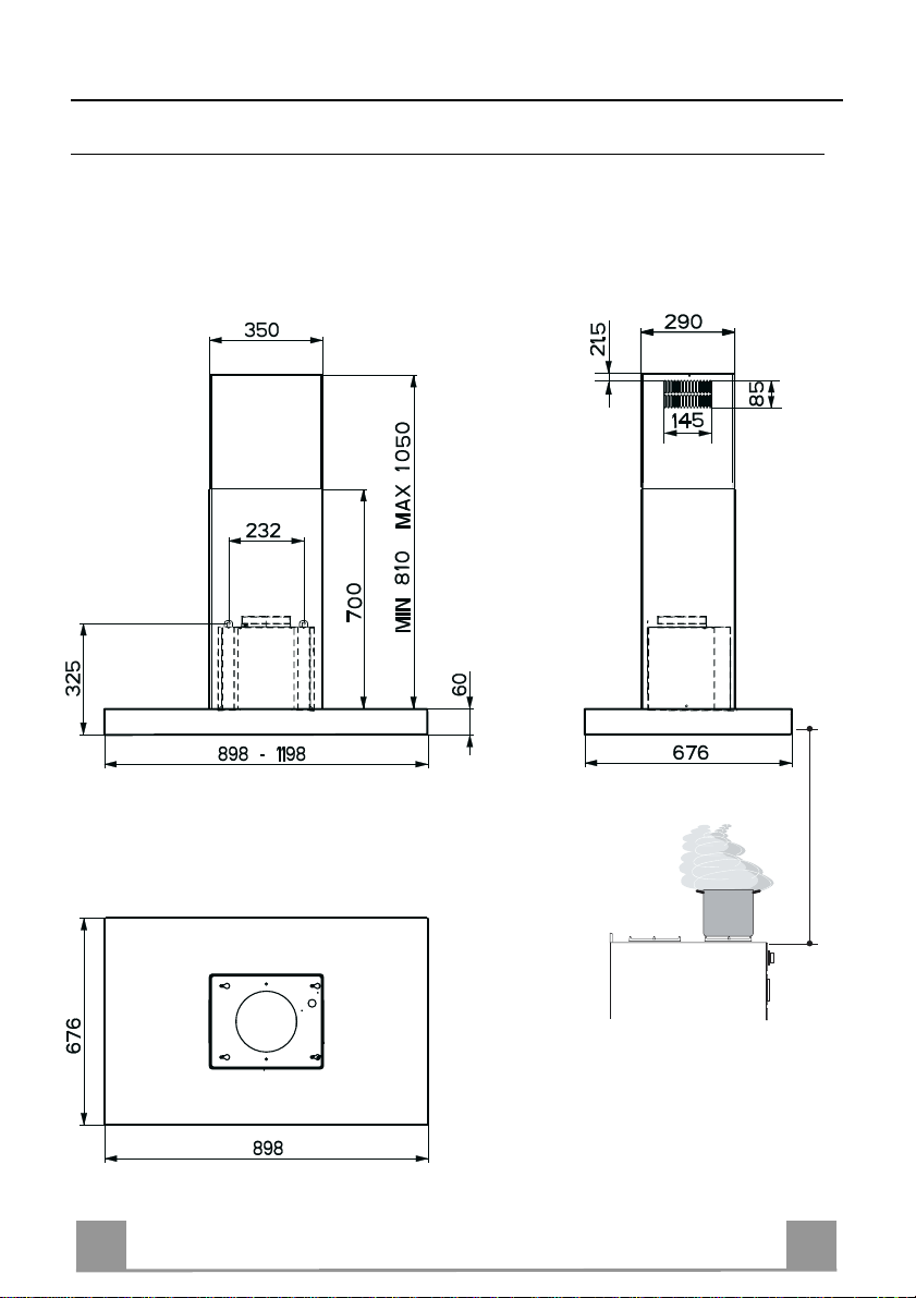
CHARACTERISTICS
Dimensions
650 min.
6
6
Page 7
EN
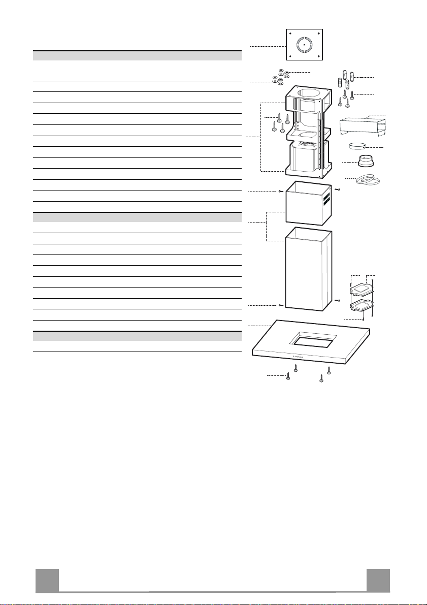
Components
Ref. Q.ty Product Components
1 1 Hood Body, complete with: Controls, Light, Blower,
Filters
2 1 Telescopic Chimney comprising:
2.1 1 Upper Section
2.2 1 Lower Section
7.1 1 Telescopic frame compl ete with extractor, consi sting of:
7.1a 1 Upper frame
7.1b 1 Lower frame
9 1 Reducer Flange ø 150-12 0 mm
10 1 Flange ø 150
15 1 Air Outlet Co nnection
24 1 Junction box
25 2 Pipe clamps
Ref. Q.ty Installation Components
11 4 Wall Plugs ø 10
12c 6 Screws 2,9 x 6,5
12e 2 Screws 2,9 x 9,5
12f 4 Screws M6 x 10
12g 4 Screws M6 x 80
12h 4 Screws 5,2 x 70
21 1 Drilling template
22 4 6.4 mm int. dia washers
23 4 M6 nuts
Q.ty Documentation
1 Instruction Manual
7.1
21
22
12c
2
12c
1
7.1a
12g
7.1b
2.1
2.2
12f
23
9
12c
11
12h
15
10
25
12e
24
7
7
Page 8
EN
INSTALLATION
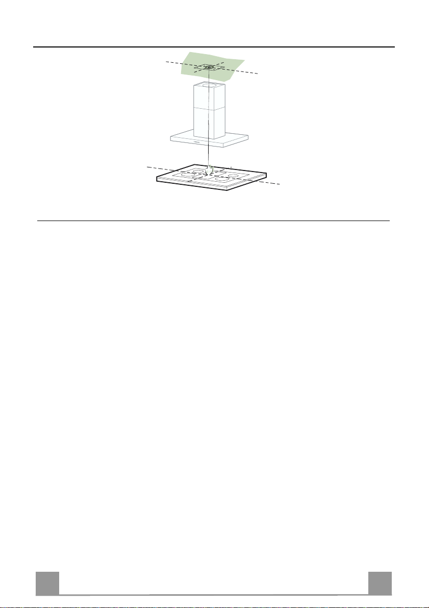
Drilling the Ceiling/shelf and fixing the frame
DRILLING THE CEILING/SHELF
• Use a plumb line to mark the centre of the hob on the ceiling/support shelf.
• Place the drilling template 21 provided on the ceiling/support shelf, making sure that the
template is in the correct position by lining up the axes of the template with those of the hob.
• Mark the centres of the holes in the template.
• Drill the holes at the points marked:
• For concrete ceilings, drill for plugs appropriate to the screw size.
• For hollow brick ceilings with wall thickness of 20 mm: drill ø 10 mm(immediately insert
the Dowels 11 supplied).
• For wooden beam ceilings, drill according to the wood screws used.
• For wooden shelf, drill ø 7 mm.
• For the power supply cable feed, drill ø 10 mm.
• For the air outlet (Ducted Versio n), drill according to t he diameter of the external air exhaust duct connection.
• Insert two screws of the following type, crossing them and leaving 4-5 mm from the ceiling:
• For concrete ceilings, use the appropriate plugs for the screw size (not provided).
• for Cavity ceiling with inner space, with wall thickness of approx. 20 mm, Screws 12h,
supplied.
• For wooden beam ceilings, use 4 wood screws (not provided).
• For wooden shelf, use 4 screws 12g with washers 22 and nuts 23, provided.
8
8
Page 9
EN
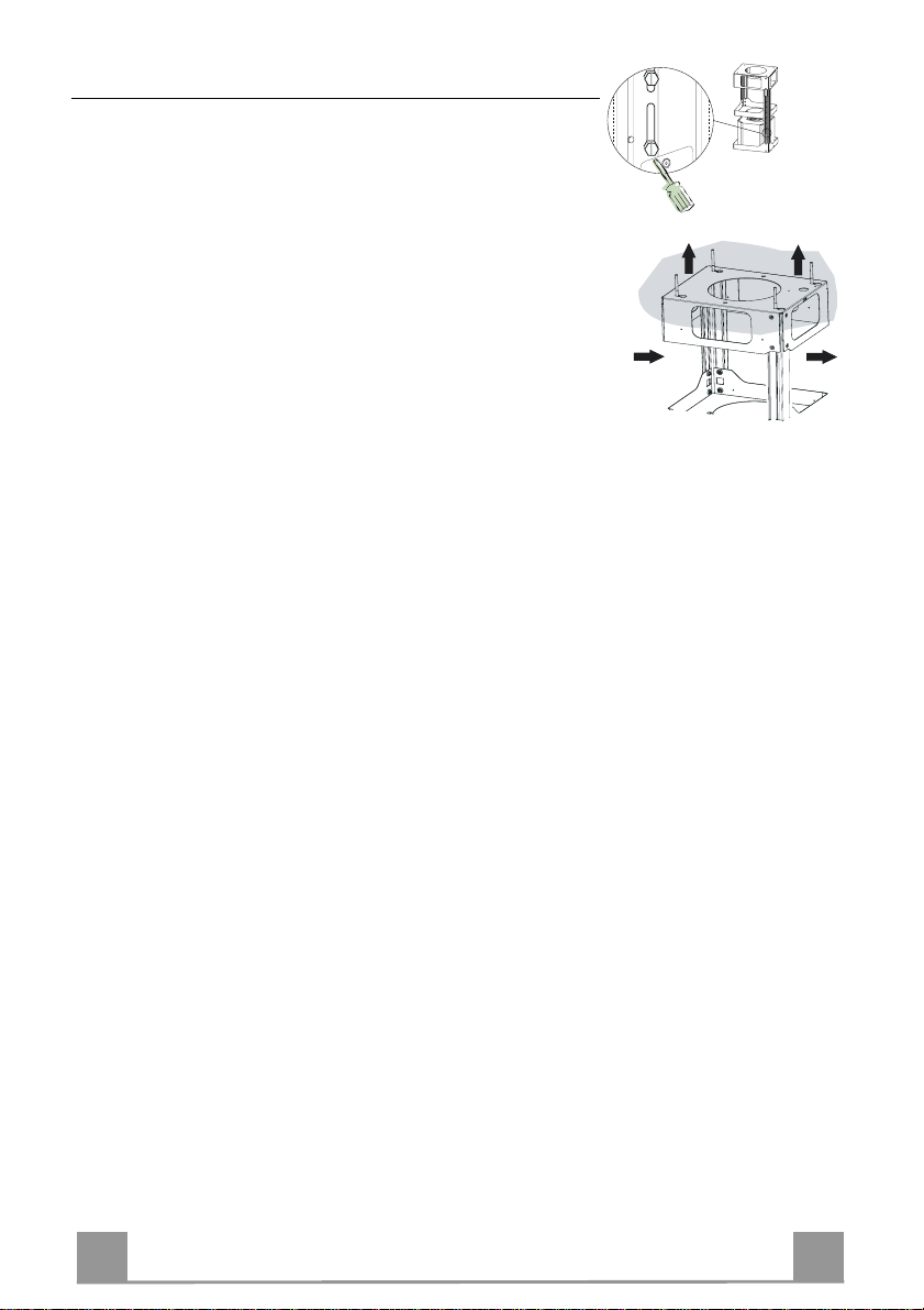
Fixing the frame
2
2
1
1
• Loosen the two scre ws fastening the lower chimney and remove this from the lower frame.
• Loosen the two screws fastening the upper chimney and remove this from the upper frame.
If you wish to adjust the height o f the frame, proceed as follows:
• Unfasten the eight metric screws joining the two columns, located at the sides of the frame.
• Adjust the frame to th e height required, then repl ace all the
screws removed as above.
• Insert the upper chimney stack from above, and leave it running free on the frame.
• Lift up the frame, fit the frame slots onto the screws up to the
slot end positions.
• Tighten the two screws and fasten the other two screws provided with the hood.
Before tightening the screws completely it is possible to adjust
the frame by turning it. Make sure that the screws do not come
out of their seats in the slotted holes.
• The frame mountings must be secure to withstand the weight
of the hood and any stresses caused by the occasional side
thrust applied to the device.
On completion, check that the base is stab le, even if the frame
is subjected to bending.
• In all cases where the ceiling is not strong enough at the suspension point, the installer must provide strengthening using
suitable plates and backing pieces anchored to the structurally
sound parts.
9
9
Page 10
EN 110
Connections
9
ø 150
ø 120
25
25
15
10
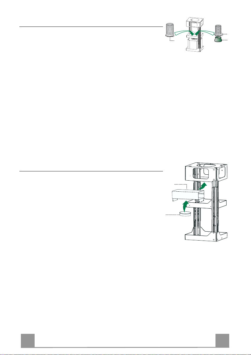
DUCTED VERSION AIR EXHAUST SYSTEM
When installing the ducted version, connect the hood to the
chimney using either a flexible or rigid pipe ø 150 or 120 mm,
the choice of which is left to the installer.
• To install a ø 120 mm air exhaust connection, insert the reducer flange 9 on the hood body outlet.
• Fix the pipe in position using sufficient pipe clamps (not supplied).
• Remove possible charcoal filters.
Recirculation version air outlet
• Fix the connection 15 to the frame using the 4 screws provided.
• Fix the flange 10 to the lower opening of the connection 15.
• Connect the hood air outlet to the flange in the lower part of
the junction using a rigid or flexible ø 150 tube (by installer’s
choice).
Page 11
EN 111
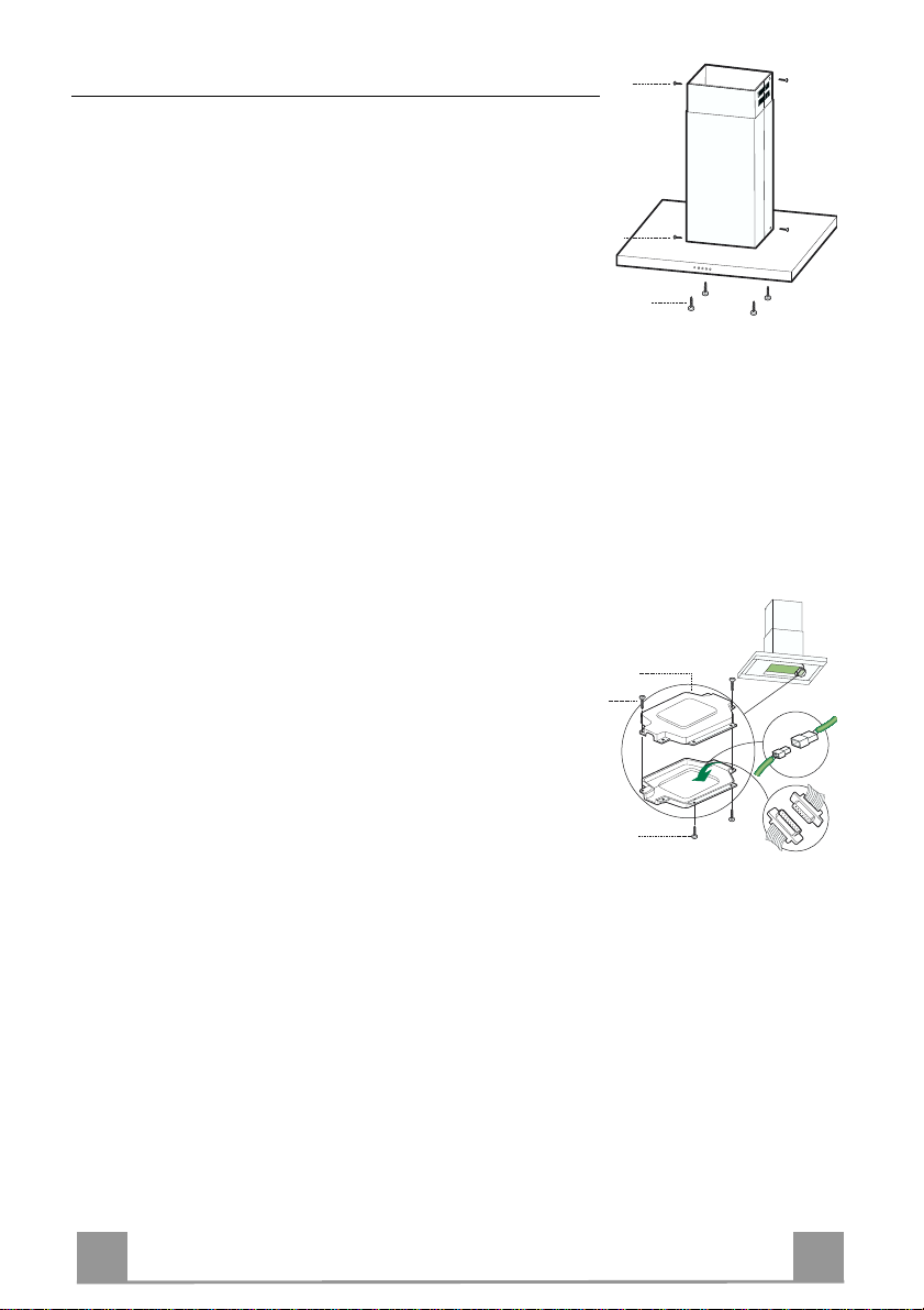
Flue assembly - Mounting the hood body
12f
12c
12c
24
12e
Cmd
12c
Lux
• Position the upper chimney section and fix the upper part to the
frame using the 2 screws 12c (2,9 x 6,5) provided.
• Similarly, position the lower chimney section and fix the
lower part to the frame using the 2 screws 12c (2,9 x 6,5) provided.
Before fixing the hood body to the frame:
• Remove the grease filters from the hood body.
• Remove any activated charcoal fil ters.
• From below, use the 4 screws 12f (M6 x 10)provided to fix the
hood body to the frame.
ELECTRICAL CONNECTION
• Connect the hood to the mains through a two-pole switch having a contact gap of at least 3 mm.
• Re move the grease filters (see paragraph Maintenance) being
sure that the conn ector of the feeding cable is correctly inserted
in the socket placed on th e side of the fan.
• Connect the control connector Cmd.
• Connect the lights connecto r Lux.
• P lace the connectors in the junction box 24 and close it using
the 2 screws 12e (2,9 x 9,5) provided.
• Fix the junction box to the hood body using the 2 screws 12c
(2,9 x 6,5) provided.
• For the recirculation version, fit the activated carbon odour filter.
• Replace the grease filters.
Page 12
EN 112
USE
Du
al Function
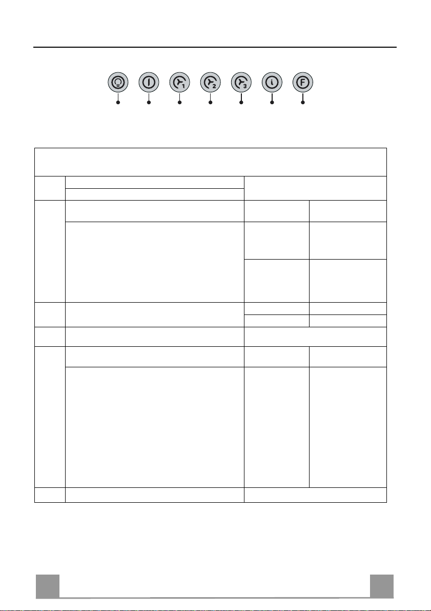
L T1 T2 T3 T4 T5 F
The hood can be switched on pushing directly onto the requested speed without firstly having to select 0/1 button .
Touch
control
T1
T2
T3
T4
Basic functions
When briefly pressed it switches the lighting system
L
on and off.
When pressed for 2 seconds it starts the lighting
system in “courtesy light” mode. The lamps are
fed at a reduced power of approximately 5W.
Such function can be stopped by pressing the
touch control for 2 seconds or just by pressing it
shortly in order to return to the normal lighting
mode. In courtesy light mode the touch control is
not lit.
When pressed the motor is stopped, regardless of the
speed it is set to.
When pressed the motor is set to the first speed
By a brief pressing the motor is set to the second
speed.
By pressing the touch control for approximately 2
seconds the Delay function is enabled, i.e de-
layed shutdown of the appliance ensuring a com-
plete elimination of the residual odours. This fun-
ction can be activated at OFF-position and at 1°,
2° and 3°speeds. It can be stopped in advance
by pressing any of the touch controls (T) with the
exception of T3. The Delay function works accor-
ding to the following scheme:
1°speed / OFF = 20 minuets
2°speed = 15 minutes
3°speed = 5 minutes
When pressed the motor is set to the third speed
Indicator lights
Touch control unlit Lights off
Touch control lit Lights on
Touch control unlit Courtesy light on
Touch control lit Motor on
Touch control unlit Motor off
Touch control lit
Touch control lit Second speed on
Flashing touch
control
Touch control lit
Delay function on
Page 13

EN 113
Touch
Touch control lit
control
T5
Basic functions Indicator lights
When pressed the motor is set to the intensive speed
timed to 5 minutes. At the end of 5 minutes of intensive speed the hood starts again at the speed it was
set to previously. In case the hood is set to the intensive speed directly from OFF-state it will then start
from the first speed after 5 minutes of intensive
speed.
When pressed for 4 seconds it resets the filter alarm
F
signal indicated by flashing of the touch control T1.
This procedure can be carried out only when the motor is stopped.
Flashing touch
control
Touch control lit
Metal grease filters saturation alarm. Metal gr e ase
filters need to be washed.
The alarm star ts up after
100 working hours.
Charcoal odour filter saturation alarm. Char coal
filter has to be replaced
and metal grease filters
washed. The alarm starts
up after 200 working
hours. (Activation; chec k
the paragraph “Odour
filter”)
Page 14

EN 114
MAINTENANCE
Grease filters
CLEANING OF THE METAL CASSETTE FILTERS
Alarm reset
• Stop the motor.
• Press the F -touch control for at least 4 seconds until the T1 -
touch control flashes.
Cleaning the filters
• Filters can be washed in the dish machine. They need to be
washed every 2 mont hs o r even more fr equ en tly in case of particularly intensive use of the hood.
• Remove the filters one by one pushing them towards the back
side of the unit and simultaneously pulling downwards.
• Any kind of bending of the filters has to be avoided when
washing them. Before fitting them again into the hood make
sure that they are completely dry.
• When fitting the filters into the hood pay attention that they are
mounted in correct position and that the handle faces outwards.
Page 15

EN 115
Odour filter (Recirculation Version)
This filter cannot be washed or regenerated, and must be replaced when the F touch control starts
to flash, or at least once ev e ry 4 months. The alarm is only trigge re d w he n the m otor is on.
Enabling/Disabling the alarm signal
• In Recirculation Version Hoods, the Filter saturation Alarm must be enabled at the time of
installation or later.
• Switch off the lights and the motor.
• Disconnect the mains power supply to the hood by removing the motor unit power supply
cable connector, switching off the power supply at the Mains or turning the Main switch off.
• Restore the connection, pressing and holding T2.
• Release the touch control, touch controls L, T2 and F will light up normally.
• Within 3 seconds press the touch control F until the key itself flashes to confirm as follows:
• 2 flashes – Charcoal odour Filter saturation Alarm ENABLED
• 1 flash - Charcoal odour Filter saturation Alarm DISABLED
REPLACING THE CHARCOAL ODOUR FILTER
Reset the alarm signal
• Stop the motor.
• Press the touch control F for at least 4 seconds, until the touch
control T1 flashes.
Replace the Filter
• Remove the metal grease filters.
• Remove the saturated charcoal filter, turn ing the fasteners p rovided.
• Fit the new filter and fasten it its correct position.
• Put the metal grease filters in their seats.
Lighting
LIGHT REPLACEMENT
20 W halogen light.
• Remove the 2 screws fixing the Lighting support, and pull it
out of from the Hood.
• Extract the lamp from the Support.
• Replace with another of the same type, making sure that the
two pins are properly inserted in the lamp holder socket holes.
• Replace the Support, fixing it in place with the two screws removed as above.
Page 16

ES 116
CONSEJOS Y SUGERENCIAS
650 mm min.
Las presentes instrucciones de servicio son válidas para diferentes modelos
de aparato; por ello puede ser posible que se describan detalles y características de equipamiento que no concuerden íntegramente con las de su aparato
concreto.
INSTALACIÓN
• El fabricante declina cualquier responsabilidad debida a los daños provocados
por una instal ación incorrecta o no conf orme con las r eglas.
• La distancia mínima de seguridad entre la encimera y la campana debe ser de
650 mm.
• Comprobar que la tensión de red corresponda a la indicada en la placa situada en el interior de la campana.
• Para los aparatos de 1ª clase asegurarse de que la instalación eléctrica doméstica posea una toma de tierra eficaz.
• Conectar la campana a la salida del aire de aspiración mediante un tubo de
120mm de diámetro como mínimo. El recorrido del tubo debe ser lo más corto
posible.
• No conectar la campana a tubos de descarga de humos producidos por combustión (cal deras, chime neas, etc.).
• En el caso que en la cocina se utilice de manera silmultánea la campana y
otros aparatos no eléctricos (por ejemplo aparatos de gas), debe existir un sistema de ventilación suficiente para todo el ambiente. Si la cocina no posee un
orificio que comunique con el exterior, hay que realizarlo para garantizar el recambio del aire.
USO
• La campana ha sido concebida exclusivamente para un uso doméstico, para
eliminar los olores de la cocina. No utilizarla de manera inadecuada.
• No dejar llamas libres de fuerte intensidad mientras la campana esté funcionando.
• Regular siempre las llamas de manera que éstas no sobresalgan lateralmente
con respecto al fondo de las ollas.
• Controlar las freídoras durante su uso: el aceite muy caliente se puede inflamar.
• No preparar alimentos flambè debajo de la campana de la cocina; peligro de
incendio
• Este aparato no tiene que ser utilizado por personas (niños incluídos) con
capacidades psíquicas, sensoriales o mentales re ducidas, o bi en por personas
sin experiencia y conocimientos en la materia, a menos que no lo hagan bajo
el control, o instruídos, por personas responsables de su seguridad.
• Controlar que los niños no jueguen con el aparato.
MANTENIMIENTO
• Antes de efectuar cualquier operación de mantenimiento, desenchufar la campana de la red eléctrica o apagar el interruptor general.
• Efectuar un mantenimiento escrupuloso e inmediato de los filtros, según los
intervalos d e tiempo aconsejados.
• Para limpiar las su perficies d e la cam pana e s suficien te utiliza r un trapo mojado y detergente líquido neutro.
Page 17

ES 117
CARACTERÍSTICAS
Dimensiones
650 min.
Page 18

ES 118
Componentes
Ref. Cant. Componentes del Producto
1 1 Cuerpo Campana dotado con: mandos, luz, filtros
2 1 Chimenea telescópica formada por:
2.1 1 Chimenea superior
2.2 1 Chimenea inferior
7.1 1 Armazón metálico telescópico dotado de Aspirador,
formado por:
7.1a 1 Armazón superior
7.1b 1 Armazón inferior
9 1 Brida de reducción ø 150-120 mm
10 1 Brida ø 150
15 1 Racor de salida del aire
24 1 Caja de conexiones
25 2 Abrazaderas ajustables
Ref. Cant. Componentes de Instalación
11 4 Tacos ø 10
12c 6 Tornillos 2,9 x 6,5
12e 2 Tornillos 2,9 x 9,5
12f 4 Tornillos M6 x 10
12g 4 Tornillos M6 x 80
12h 4 Tornillos 5,2 x 70
21 1 Plantilla de perforación
22 4 Arandelas øi 6,4
23 4 Tuercas M6
Cant. Documentación
1 Manual de ins trucciones
7.1
21
22
12c
2
12c
1
7.1a
12g
7.1b
2.1
2.2
23
9
12c
11
12h
15
10
25
12e
24
12f
Page 19

ES 119
INSTALACIÓN
Taladrado del cielorraso/repisa y fijación del armazón metálico
TALADRADO CIELORRASO/REPISA
• Con la ayuda de un hilo de plomo marcar en el cielorraso/repisa de soporte el centro del plano de cocción.
• Apoyar en el cielorraso/repi sa la pl anti lla de tal adr ado 21 en dotaci ón , h aciend o coinci di r su
centro con el centro proyectado y ali neando l os ejes de la plan tilla con l os ejes del plano de
cocción .
• Marcar los centros de los orificios de la plantilla.
• Taladrar los puntos marcados:
• Cielo de hormigón macizo: según los tacos para hormigón empleados.
• Cielo de ladrillos huecos, con espesor resistente de 20 mm: ø 10 mm (inserir rápidamente
los Tacos 11 en dotación).
• Cielo con vigas de madera: según los tornillos para madera empleados.
• Repisa de madera: ø 7 mm.
• P aso del cable eléctrico de alimentación: ø 10 mm.
• Salida aire (Versión Aspirante): según el diámetro de la conexión a la tubería de evacua-
ción externa.
• Atornillar, cruzándolas y dejando 4-5 mms del techo, dos tornillos:
• Para hormigón macizo, tacos para hormigón, no en dotación.
• P ara Ladrillo con cámaras de aire, con espesor resistente de unos 20 mms , Tornillos 12h,
en dotación.
• Para vigas de madera, 4 tornillos para madera, no en dotación.
• Para repisa de madera, 4 tornillos 12g con arandelas 22 y tuercas 23, en dotación.
Page 20

ES 220
FIJACIÓN DEL ARMAZÓN
2
2
1
1
• Desenroscar los dos tornillos que sujetan la chimenea inferior y
sacarla del armazón (por la parte inferior)
• Desenroscar los dos tornillos que sujetan la chimenea superior
y sacarla del armazón (por la parte superio r)
En el caso en que se desee regular la altura del armazón, proceder
de la siguiente manera:
• Destornillar los ocho tornillos métricos que unen las dos co-
lumnas, situados a los lados del armazón.
• Regular a la altura deseada al armazón y volver a atornillar
los tornillos que se han quitado previamente.
• Colocar la chimemea superior desde arriba y dejarla lib re en
el armazón.
• Levantar el armazón, encajar los ojales en los tornillos y
deslizarlos hasta el fondo;
• Apretar los dos tornillos y atornillar los otros dos de la dota-
ción;
Antes de apretar definitivamente los tornillos pueden realizae regulaciones moviendo el armazón, prestando atención a que los
tornillos no sobresalgan de la sede del ojal de regulación.
• La fijación del armazón debe ser segura, hay que considerar el
peso de la campana y el esfuerzo causado por eventuales
empujes laterales al aparato montado. Una vez terminada la
fijación verificar que la base sea estable aunque el armazón sea
sometido a flexión.
• En todos los casos en que el cielo raso no es lo su ficient emente
robusto en el punto de suspensión, el instalador deberá encargarse de reforzarlo con chap as y contrachapas adecuadas ancladas en partes estructuralmente resi st entes.
Page 21

ES 221
Conexiones
9
ø 150
ø 120
25
25
15
10
SALIDA DEL AIRE VERSIÓN ASPIRANTE
Para la instalación de la versi ón asp irant e, co nect ar la ca mpana a l
tubo de salida mediante un tubo rígido o flexible de ø150 o 120
mm, a discreción del instalador.
• Para la conexión con el tubo de ø120 mm, introducir la brida de
reducción 9 en la salida del cuerpo de la cam pana.
• Fijar el tubo con abrazaderas adecuadas. Este material no se
proporciona en dotación.
• Quitar los filtros antiolor al carbón activo.
Salida del aire version filtrante
• Sujetar el empal me 15 al armazón usando los cuat ro tornillos
incluídos en la dotación.
• Encajar la arandela 10 en el correspondiente orificio inferior
del empalme 15.
• Conectar la salida del aire de la campana con la arand ela situa-
da debajo del empalme mediante un tubo rígido o flexible Ø
150 cuya elección se deja al instalador
Page 22

ES 222
Montaje de la chimenea y fijación del cuerpo de la campana
12f
12c
12c
24
12e
Cmd
12c
Lux
• Colocar la chimenea superior y fijarla en la parte superior del
armazón con 2 tornillos 12c en dotación.
• De igual manera, colocar la chimenea inferior y fijarla en la
parte inferior del armazón con 2 tornillos 12c en dotación.
Antes de fijar el cuerpo de la campan a al armazón :
• Quitar los filtros antigrasa del cuerpo de la campana.
• Quitar eventuales filtros antiolor de carbón activo.
• Luego fijar desde abajo, con 4 tornillos 12f en dotación, el
cuerpo de la campana al armazó n predispuesto.
CONEXIÓN ELÉCTRICA
• Conectar la campana a l a red de alimentación eléctrica insta-
lando un interruptor bipolar con apertura de los contactos de 3
mm como mí n imo.
• Quitar los Filtros antigrasa y asegurase de que el conector del
Cable de acometida esté colocado correctamente en el enchufe del Aspirador.
• Conectar el conector de los mandos Cmd.
• Conectar el conector de los focos Lux.
• Colocar ambos conectores en l a caja d e protección
24 cerrándola con los 2 tornillos 12e(2,9 x 9,5) en dotación.
• Fijar la caja de pro tección en el cuerpo de la campana con 2
tornillos 12c (2,9 x 6,5) en dotación.
• Para la versión filtrante montar el filtro antiolor de carbón acti-
vo.
• Montar nuevamente los filtros antigrasa.
Page 23

ES 223
USO
L T1 T2 T3 T4 T5 F
La campana puede encen derse directamente a la velocidad desea da, presionando la tecla
correspondiente sin pasar por la tecla 0/1 motor.
Función base Tecla
Señalizaciones luminosas
Doble Función
Presionada brevemente enciende y apa ga la instalación
L
de iluminación.
Al presionar la tecla por 2 segundos se activa la instalación de iluminación en modalidad “luz auxiliar”
Las lámparas son alimentadas a una potencia reducida de aproxi madamente 5 W . Dicha func ión puede
desconectarse volviendo a presionar la tecla por 2
segundos o pr esionándol a brevemente para pasar a
la modalidad de i luminación nor mal. En la modalidad luz auxiliar la tecla no está iluminada.
Apaga el motor desde cualquiera veloci dad implementa-
T1
da
Activa el motor a la primera velocidad
T2
Presionada brevemente activa el motor a la segunda
T3
velocidad
Al presionar por aproxima damente 2” la tecla, se activa la función Delay es decir el apag ado retrasado
del aparato. Adecuada para completar la eliminación
de olores residuales. Act ivable desde la posición
OFF y desde las velocidades 1,2,3, se de sactiva anticipadamente presionando cualquier tecla (T) a excepción de T3. El Delay se produce según el siguiente esquema.
1° velocidad / OFF = 20 minutos
2° velocidad = 15 minutos
3° velocidad = 5 minutos
Activa el motor a la tercera v elocidad
T4
Tecla
apagada
Tecla
iluminada.
Tecla
apagada
Tecla
iluminada.
Tecla
apagada
Tecla
encendida
Tecla
intermitente
Luces apagadas
Luces encen didas
Luz auxiliar encendida
Motor activo
Motor inactivo
Tecla encendid a
Segunda velocidad activa
Función Delay Acti v a
Tecla encendid a
Page 24

ES 224
Tecla Función base Señalizaciones luminosas
Activa el motor a la velocidad intensiva tempori-
T5
zada en 5 minutos. Al final de los 5 minutos el
aparato vuelve a la velocidad implementada precedentemente. En el caso de activación desde
aparato apagado al vencer los 5 minutos el sistema vuelve a la pr imera velocidad.
Presionado por 4 segundos restablece la señali-
F
zación de alarma filtros señalándola con el parpadeo de la tecla T1. Este procedimiento es ejecutable sólo c on el motor apagado.
Tecla encendid a
Tecla encendida
Tecla intermitente
Señala la alarma de saturación
Filtros Antigrasa Metálicos y la
necesidad de lavarlos. La alarma
entra en función después de
100horas de trabajo efectivo de
la Campana
Señala, cuando está activada, la
alarma de saturación Filtro Antiolor al Carbon o Activo que debe
ser sustituido;deben lavarse
además los filtros Antigrasa
Metálicos. La alarma de
saturación Filtro Antiolor al
Carbono Activo entra en función
después de 200 hora s de trabajo
efectivo de la Campana
(Activación ver párr. Filtro
antiolor)
Page 25

ES 225
MANTENIMIENTO
Filtros antigrasa
LIMPIEZA DE LOS FILTROS ANTIGRASA METALICOS AUTOPOR-
TANTES
Reset de la señal de alarma
• Apagar el motor de aspiración
• Apretar la tecla F durante 4 segundos, hasta que relampaguee
la tecla T1
Limpieza de los filtros
• Se pueden lavar en el lavavajillas cada 2 meses ó con mayor
frecuencia si se usa la campan a intensamente.
• Quitar los filtros uno a la vez, apretándolos hacia la parte pos-
terior del grupo y tirando contemporaneamente hacia abajo.
• Lavar los filtros sin doblarlos, y dejar que se sequen bien antes
de volver a colocarlos.
• Volver a colocarlos prestando atención a que la manilla quede
hacia el lado exterior visible.
Page 26

ES 226
Filtro antiolor (Versión Filtrante)
No se pueden lavar y no son regenerables, hay que substituirlos cuando la tecla F relampaguea
ó, por lo menos, cada 4 meses. La señalación de alarma se v erifica solo cuando el motor de
aspiración funciona.
Activación/Desactivación de la señal de alarma
• En las campanas en versión filtrante, la señalación de la alarma de saturación de los filtros
se activa cuando se instala la campana ó sucesivamente.
• Apagar las luces y el motor de aspiración.
• Desconectar la campana, quitando el cable de acometida, desenchufándola ó quitando mo-
mentaneamente los plomos.
• Volver a conectar la campana apretando la tecla T2.
• Soltar la tecla, las teclas L, T2 y F se quedan encendidas.
• En el espacio de 3 segundos apret ar l a t ecla F hasta que relampaguee:
• 2 relampagueos - Alarma saturación filtro antiolor al carbón ACTIVADO
• 1 relampagueo - Alarma saturación filtro antiolor al Carbón DESACTIVADO
SUBSTITUCION FILTRO ANTIOLOR AL CARBON ACTIVO
Reset del señal de alarma
• Apaga el motor de aspiración.
• Apretar la tecla F durante 4 segundos, hasta que relampaguee
la tecla T1.
Substituci ó n del fil t ro
• Quitar los filtros antigrasa metálicos.
• Quitar el filtro antiolor al carbón activado saturado, maniobrando en los enganches correspondientes.
• Volver a colocar el filtro nuevo enganchándolo en su sede.
• Volver a colocar los filtros antigrasa metálicos.
Iluminación
SUSTITUCIÓN DE LAS BOMBILLAS
Lámparas halógenas de 20 W
• Quitar los dos tornillos que fijan el soporte.
• Extraer la lámpara desde el soporte.
• Susti tuirla con una nueva con l as mismas características, po niendo cuidado en insertar correctamente los dos enchufes en
el asiento del soporte.
• Montar nuevamente el soporte fijándolo con los dos tornillos
que se habían quitado precedentemente.
Page 27

PT 227
CONSELHOS E SUGESTÕES
650 mm min.
Estas instruções de serviço aplicam-se a vári os m odel os de aparelhos. É.
por isso, possível que se encontrem descritas várias características de
equipamento que não dizem respeito ao seu aparelho.
INSTALAÇÃO
• O fabricante declina toda e qualquer responsa bilidade pelos danos decorrentes de uma instalação n ão co rrecta ou feita não em conformidade com
as normas da boa técnica.
• A distância mínima de seguranç a entre a plac a de co zedura e o exa ustor
deve ser de 650 mm.
• Verifique se a tensão da rede coincide com a indicada na pl aca de car acterísticas aplicada no interior do exaustor.
• Para os aparelhos de Classe I
tica garanta uma descarga correcta à terra.
• Ligue o exaustor à saída do ar aspirado utilizando um tubo de diâmetro
igual ou superior a 1 20 mm. O percur so do tubo deve ser o m ais breve
possível.
• Não ligu e o exaustor a t ubos de desca rga de fumaça p roduzida porcom bustão (caldeiras, lareiras, etc...).
• Caso no mesmo local sejam utilizado s quer o exaustor, quer aparelhos
não accionados pela corr ente eléct rica (por exem plo, aparelh os alim entados a gás), será preciso providenciar uma ventilação suficiente do aposento. Se a cozinha não possui r uma abert ura que com unique com o exterior, providencie a sua realização para garantir a entrada de ar limpo.
USO
• O exaustor foi projectado para ser utilizado exclusivamente em am bientes
domésticos, sendo a sua fin alidade a de reduzir os odores de cozedura.
Não utilize o aparelho de maneira imprópria.
• As chamas de forte intensi dade não devem ficar descobertas enquanto o
exaustor estiver a funcionar.
• Regule sempre as chamas de maneira que não sob ressaiam do fundo
das panelas.
• Mantenha as frigideiras sob controlo d u rante o uso: o óleo excessivamente aquecido pode inflamar-se.
• No prepare alimentos flamejados sob o exaustor. Perigo de incêndio!
• Este aparelho não deve ser utilizado por pessoas (incluindo crianças)
diminuídas psíquica, sensori al ou mentalmente nem por i ndivíduos sem
experiência e conhecimento, salv o se vigiados ou instruídos para utilização do aparelho por pessoas responsáveis pela respectiva segurança.
• As crianças devem ser vigiadas no sentido de asseg urar que não brinquem com o aparelho.
a
, certifique-se de qu e a instalação domés-
MANUTENÇÃO
• Antes de efectuar qualquer operação de manutenção, desligue o exaustor
tirando a ficha da tomada de corrente ou desligando o interruptor geral.
• Faça uma manutenção atenta e r ápida dos fi ltros , respeit and o os i ntervalos aconselhados.
• Para limpar as superfícies do exaustor, é suficiente utilizar um pano húmido e detergente líquido neutro.
Page 28

PT 228
CARACTERÍSTICAS
Dimensões
650 min.
Page 29

PT 229
Componentes
Ref. Qtd Comp onentes do pro duto
1 1 Corpo do exaustor equipado com: Comandos, ilumina-
ção e filtros
2 1 Chaminé tel escópica formada por:
2.1 1 Chaminé superior
2.2 1 Chaminé inferior
7.1 1 Armação telescópica provida de aspirador formada
por:
7.1a 1 Armação superior
7.1b 1 Armação inferior
9 1 Flange de redução ø 150-120 mm
10 1 Flange ø 150
15 1 Conexão da saída de ar
24 1 Caixa de ligações
25 2 Braçadeiras para tubos
Ref. Qtd Componentes de instalação
11 4 Buchas ø 10
12c 6 Parafusos 2,9 x 9,5
12e 2 Parafusos v 2,9 x 6,5
12f 4 Parafusos M6 x 10
12g 4 Parafusos M6 x 80
12h 4 Parafusos 5,2 x 70
21 1 Gabarito de perfuraçã o
22 4 Anilhas øi 6, 4
23 4 Porcas M6
Qtd Documentação
1 Manual de Instruções
7.1
21
22
12c
2
12c
1
7.1a
12g
7.1b
2.1
2.2
12f
23
9
12c
11
12h
15
10
25
12e
24
Page 30

PT 330
INSTALAÇÃO
Perfuração do tecto/prateleira e fixação da armação
PERFURAÇÃO DO TECTO/PRATELEIRA
• Com a ajuda de um fio de prumo, marque noTecto/Prateleira de suporte o ponto de projecção do centro da placa do fogão.
• Apoie o gabarito de perfuração 21, que acompanha o aparelho, no tecto/prateleira de modo a
fazer com que o centro deste coincida com o centro projectado e alinhando os eixos do gabarito com os eixos da placa do fogão.
• Marque os centros dos furos do gabarito.
• Fure os pontos marcados:
• Tecto de betão maciço: de acordo com as buchas para betão utilizadas.
• Tecto de tijolo perfurado, com espessura resistente de 20 mm: ø 10 mm (introduza imedi-
atamente as buchas 11 fornecidas juntamente com o aparelho).
• Tecto de traves de madeira: de acordo com os parafusos para madeira utilizados.
• P r ateleira de madeira: ø 7 mm.
• P assagem do fio eléctrico de alimentação: ø 10 mm.
• Saída d e ar (versão aspirant e): de acord o com o d iâmetro d a ligação à tubagem d e evacu-
ação exterior.
• Enrosque dois parafusos, cruzando-os e deixando-os a 4-5 mm de distância do tecto:
• para betão maciço, buchas para betão (não fornecidas com o aparelho).
• para tijolos ocos com espessura resistente, de cerca de 20 mm, Parafusos 12h, fornecidos
com o aparelho.
• para traves de madeira, 4 parafusos para madeira (não fornecidos com o aparelho).
• para prateleira de madeira, 4 parafusos 12g (M6 x 80) com anilhas 22 e porcas 23 (forne-
cidas com o aparelho).
.
Page 31

PT 331
FIJACIÓN DEL ARMAZÓN
2
2
1
1
• Desaperte os dois parafusos que estão a fixar a chaminé inferior e desenfiá-la da armação (por baixo).
• Desaperte os dois parafusos que estão a fixar a chaminé superior e desenfiá-la da armação (por cima) .
Se desejar ajustar a altura da armação, proceda do modo seguinte:
• Desaperte os oito parafusos métricos que estão a unir as duas colunas dispostas de ambos os lados da armação.
• Regule a altura de armação desejada e aperte de novo os parafusos tirados anteriormente.
• Introduza a chaminé superior por cima e deixe-a livre por cima
da armação.
• Levante a armação, enfie os orifícios oblongos nos parafusos e
deslize com ela até ao limite de curso;
• Aperte bem os dois parafusos e aplique os outros dois incluídos
nos acessórios fornecidos de série.
Antes de apertar os parafusos definitivamente é possível fazer
ajustes, deslocando a armação, prestando atenção aos parafusos
que não podem sair da sede do orifício oval de regulação.
• A fixação da armação deve ficar segura, quer em relação ao
peso do exaustor, quer em relação a esforços provocados por
pressões laterais ocasionais no aparelho montado. Terminada a
fixação,
verifique a estabilidade da base e experimente-a, sobretudo
submetendo-a a esforço de flexão.
• Nos casos em que o tecto não for suficientemente forte no ponto de suspensão, o instalador terá de o reforçar colocando placas e contraplacas fixadas às partes estruturais resistentes.
Page 32

PT 332
Ligações
9
ø 150
ø 120
25
25
15
10
Para a instalação na V ersão Aspirante, ligue o exausto r ao tubo
de saída utilizando um tubo rígido ou flexível de ø150 ou 120
mm; esta escolha deve ser feita pel o instalador.
• Para a ligação co m um tubo de ø120 mm, instale a flange de
redução 9 na saída do corpo do exaustor.
• Fixe o tubo com braçadeiras de aperto adequadas. O material
necessário não é fornecido com o aparelh o.
• Tire os filtros anti-odor de carvão activo, se pre sente s..
SAÍDA DO AR PARA A VERSÃO ASPIRANTE
Saída de ar da versão filtrante
• Fixe a conexão 15 à armação, usando os 4 parafusos fornecidos.
• Encaixe a flange 10 no furo específico inferior da conexão 15.
• Ligue a saída de ar do exaustor à flange posta por baixo da conexão, utilizando um tubo de ø 150, rígido ou flexível, à escolha do instalador.
Page 33

PT 333
Montagem da chaminé e fixação do corpo do exaustor
12f
12c
12c
24
12e
Cmd
12c
Lux
• Posicionar a chaminé superior e fixá-la, na sua parte superior,
à peça de fixaçao com dois parafusos 12c (2,9 x 6,5) provistos.
• Introduza a chaminé inferior na armação, segurando-a na sua
posição até à montage m do corpo do exaustor.
Antes de fixar o corpo do exau st or à armação:
• Desmonte os filtros antigordura do corpo do exaustor.
• Desmonte os filtros anti-odor, de carvão activo, eventualmente
montados.
• Fixe então, por baixo, o corpo do exaustor à armação montada,
com os 4 parafusos 12f (M6 x 10) fornecidos com o aparelho.
LIGAÇÃO ELÉCTRICA
• Ligue o exaustor à rede d e alimentação eléctrica intercalando
um interruptor bipolar com abertura mínima entre os contactos
de 3 mm.
• Remova o filtro de gordura e assegure que o conector de alimentação esta corretamente in serido no suporte lateral do ventilador.
• Ligue o conector dos comandos Cmd.
• Ligue o conector dos focos Lux
• Coloque ambos os conectores na caixa de protecção 24, fechando-a com os 2 parafusos 12e (2,9 x 9,5) fornecidos com o
aparelho.
• Fixe a caixa de protecção ao corpo do exaustor co m os 2 parafusos 12c (2,9 x 6,5) fornecidos como aparelho.
• P ara a versão filtrante, monte o filtro anti-odor de carvão activo.
• Reinstale os filtros antigordura.
Page 34

PT 334
UTILIZAÇÃO
L T1 T2 T3 T4 T5 F
O exaustor pode ser ligado directamente na velocidade desejada, premindo a respectiva tecla, sem passar pela tecla 0/1 do motor.
Tecla
Função de base
Indicações luminosas
Dupla função
Premido rapidamente, liga e desliga o sistema de
L
iluminação.
Premindo a tecla du rante 2 segundos, o
sistema de iluminação activa-se no modo “luz
de cortesia”. As luzes são alimentadas com a
potência reduzida de 5W, aprox. A função poderá ser desactivada premindo de novo a
mesma tecla 2 segundos ou, premindo rapidamente, para passar ao modo de iluminação
normal. No modo luz de cortesia a tecla não
está iluminada.
Desliga o motor, seja qual for a velocidade a que
T1
estiver a funcionar
Põe o motor a funcionar com a primeira velocida-
T2
de
Premido rapidament e, liga o motor pondo-o a fun-
T3
cionar com a segunda velocidade.
Premindo a tecla d urante cerca de 2”, act iv ase a função Delay, ou seja, a desactivação
automática retardada do aparelho. Indicado
para completar a eliminação de cheiros residuais. Activável da posição OFF e das
velocidades 1, 2, 3 ; de s activa-se
antecipadamente, premindo uma qualquer das
teclas (T), excluindo a T3. O Delay ocorre segundo o esquema seguinte:
1° velocidade / OFF = 20 minutos
2ª velocidade = 15 minutos
3ª velocidade = 5 minutos
Põe o motor a funcionar com a terceira veloc idade
T4
Tecla
desligada
Tecla
iluminada
Tecla
desligada
Tecla
iluminada
Tecla
desligada
Tecla acesa Segunda velocidade ac-
Tecla intermitente
Luzes apagadas
Luzes acesas
Luz de cortesia acesa
Motor activo
Motor inactivo
Tecla acesa
tiva
Função Delay
Activada
Tecla acesa
Page 35

PT 335
Tecla
velocidade que estava definida anteriormente.
T5
F
Função de base
Liga o motor com velocidade intensa durante
um período de tempo de 5 minu tos. Ao fim de 5
minutos, o aparelho regressa automaticamente
à
Em caso de activação partindo do estado de
aparelho desligado, o sistema, no prazo de 5
minutos, regressa à primeira velocidade.
Premida durante 4 seg undos, repõ e a indicaçã o
de alarme dos filtros, indicando-a através da
intermitência da tecla T1. Este processo só é
executável com o motor desligado.
Indicações luminosas
Tecla acesa
Tecla acesa Sinaliza o alarme de saturação dos
Tecla
intermitente
filtros de metal antigordura e a necessidade de os lavar. O alarme
dispara ao fim de 100 horas de funcionamento efectivo do exaustor.
Sinaliza que está activado o alarme
de saturação do filtro anti-odores de
carvão activo e, portanto , que é necessário substituí-lo. De vem lavar-se
também, nesta altura, os filtros de
metal antigordura. O alarme de saturação do filtro anti-o dores de carvão
activo dispara ao fim de 200 horas
de funcionamento efectivo do exaustor. (Activação ver parág. Filtro anti-
odores)
Page 36

PT 336
MANUTENÇÃO
Filtros antigordura
LIMPEZA DOS FILTROS METÁLICOS ANTIGORDURA AUTOPORTANTES
Reset do sinal de alarme
• Desligue o motor de aspiração.
• Pressione o botão F durant e, pelo menos , 4 segun dos, at é receber confirmação através os led T1 que começam a piscar.
Limpeza dos filtros
• Podem ser lavados em máquinas de lavar louça. A operação de
lavagem deve ser feita quando de 2 em 2 meses de utilização,
com maior frequência se o aparelho for utilizado com muita intensidade.
• Tire os filtro abrindo os respectivos engates.
• Lave os filtros evitando dobrá-los e deixe-os secar antes de os
reinstalar.
• Reinstale-os lembrando-se de manter a pega virada para a parte
visível exterior.
Page 37

PT 337
Filtro anti-odores (Versão Filtrante)
Não é lavável nem regenerável. Tem de ser substituído quando a tecla F começa a piscar ou,
pelo menos, de 4 em 4 meses. A sinal ização do alarme só se verifica quando o motor de exaustão estiver ligado.
Activação/desactivação do sinal de alarme
• Nos exaustores na versão filtrante, a sinalização do alarme de saturação dos filtros tem de
ser activada na altura de instalação do exaustor, ou posteriormente.
• Desligue as luzes e o motor de exaustão.
• Desligue a alimentação de rede do exaustor, removendo o conector do cabo de alimentação
do grupo do motor ou accionando o interruptor bipolar colocado na alimentação de rede ou
desligando o interruptor geral.
• Repor a ligação, mantendo premida a tecla T2.
• Libertar a tecla; as teclas L, T2 e F estão acesas em posição fixa.
• No prazo de 3 segundos prima a tecla F até esta começar a piscar, em sinal de confirmação:
• 2 sinais intermitentes - Alarme de saturação do filtro de carvão anti-odores, ACTIVADO
• 1 sinal intermitente - Alarme de saturação do filtro de carvão anti-odores, DESACTIVADO
SUBSTITUIÇÃO DO FILTRO DE CARVÃO ACTIVO
Reset do sinal de alarme
• Desligue as luzes e o motor de aspiração.
• Pressione o botão F durant e, pelo menos , 4 segun dos, at é receber confirmação através os led T1 que começam a piscar.
Substituição do Filtro
• Tire os filtros metálicos antigordura.
• Re mova o filtro anti-odor de carvão activo saturado, conforme
indicado.
• Monte o filtro novo prendendo-o na sua sede.
• Reinstale os filtros metálicos antigordura.
Iluminação
SUBSTITUIÇÃO DAS LÂMPADAS
Lâmpadas de halogéneo de 20 W
• Tire os 2 parafusos que fixam o suporte de iluminação e extraia-o do exaustor.
• Extraia a lâmpada do supo rte.
• Substitua-a por uma nova de características iguais lembrandose de introduzir correctamente os dois pinos na sede do suporte.
• Reinstale o suporte fixando-o com os dois parafusos tirados na
operação anterior.
Page 38

Page 39

Page 40

The symbol on the product or on its packaging indicates that this pr o d uc t m ay n ot b e tr e ated as household waste. Ins tead it shall
be handed over to the appl icable col lection p oint for t he recycli ng of electr ical and el ectronic equipment . By ensurin g this product is
disposed of correctly, you will help prevent potential negative consequences for the environment and human health, which could otherwise be caused by inap propr iat e wast e ha ndl ing of this pro duc t. For mor e det ail ed inf ormati o n about recy cli ng of this pro duc t, ple ase
contact your local city office, your household waste disposal service or the shop where you purchased the product.
El símbolo en el producto o en su embalaje indi c a q ue es te producto no se pu e de tratar como desper di c i os normales del hogar.
Este product o se de be entre g ar al p unt o de r ec olec ci ón d e equi pos el éctri cos y el ectr óni cos p ar a reci cl aje. A l as eg urars e d e qu e est e
producto se des eche c orrec tame nte, us ted ay udar á a evi tar posi bles c onsec uenci as neg ativas par a el ambi ente y l a salu d públ ica, lo
cual podría oc urrir si este pr oduct o no se mani pula de form a adec uada. P ara obte ner inf orma ción más detall ada so bre el r ecicl aje de
este product o, pó ngas e e n c ontac to c on l a a dm ini str ación d e su ci ud ad, c on s u s ervi ci o de desec hos del hog ar o co n la tien da d onde
compró el producto.
O símbolo no produto ou na emb alagem indica que este pr o du to não pode ser tratado c omo lixo doméstico. Em vez disso, deve
ser entregu e ao centro de recolha sel ectiva para a reciclag em de equip amento eléctr ico e elec trónico. Ao garantir uma eliminação
adequada deste produto, irá ajud ar a ev i t ar eventuais consequê nci as negativas para o meio ambiente e para a sa úde pública, que, de
outra forma, p oderiam ser provocadas p or um tratamento incorrecto d o produto. Para obter inf o r m aç õ es m ai s p or m en or i zadas sobre a
reciclagem des te pro duto, con tacte os s erviços munici palizados locai s, o centr o de recol ha sel ectiva da s ua área de r esidê ncia ou o
estabelecimento onde adquiriu o produto.
436003794_ver2
 Loading...