

Page 1

DD 9864 - DD 9874 - DD 9894
User manual Cooker Hood
Page 2

Contents
Safety warnings ................................................................................ 3
Description of the Appliance ........................................................... 5
Extraction mode ................................................................................. 5
Recirculation mode............................................................................. 5
Control Panel .................................................................................... 6
Maintenance and Care ..................................................................... 8
Metal grease filter ............................................................................... 8
Charcoal filter ..................................................................................... 9
Warning ............................................................................................ 10
Changing the light bulbs ................................................................... 10
Cleaning the hood ............................................................................ 10
Special accessories ....................................................................... 11
Technical assistance service......................................................... 11
Technical Details ............................................................................ 11
Mounting accessories included ........................................................ 11
Electrical connection ..................................................................... 12
Installation ........................................................................................ 13
2
Page 3

Safety warnings
• When used as an extractor unit, the hood must be fitted with a hose
having preferably the same diameter as the outlet hole.
Should there already be a pipe of diameter 125 mm that ducts to
the outside through the walls or roof, it is possible to use the 150/
125 mm reduction flange provided. In this case the hood will be
slightly noisier.
Attention: The hose is not supplied and must be purchased
separately.
• The minimum distance between the supporting surface for the
cooking vessels on the hob and the lowest part of the range hood
must be not less than 50cm from electric cookers and 65cm from
gas or mixed cookers.
If the instructions for installation for the gas hob specify a greater
distance, this must be adhered to.
• Before any cleaning or maintenance operation, disconnect the hood
from the mains by removing the plug or disconnecting the home
mains switch.
• The appliance is not intended for use by children or persons with
impaired physical, sensorial or mental faculties, or if lacking in
experience or know-how, unless they are under supervision or have
been trained in the use of the appliance by a person responsible for
their safety.
• Children should be monitored to ensure that they do not play with
the appliance.
• Never use the hood without effectively mounted grating.!
• The hood must NEVER be used as a support surface unless
specifically indicated.
• The premises must be sufficiently ventilated, when the kitchen hood
is used together with other gas combustion devices or other fuels.
• The suctioned air must not be conveyed into a conduit used for the
disposal of the fumes generated by appliances that combust gases
or other fuels.
• The flaming of foods beneath the hood itself is severely prohibited.
• The use of exposed flames is detrimental to the filters and may
cause a fire risk, and must therefore be avoided in all
circumstances.
• Any frying must be done with care in order to make sure that the oil
does not overheat and burst into flames.
• As regards the technical and safety measures to be adopted for
fume discharging it is important to closely follow the relations
3
Page 4
provided by the competent authorities.
• The hood must be regularly cleaned on both the inside and outside
(AT LEAST ONCE A MONTH, it is in any event necessary to
proceed in accordance with the maintenance instructions provided
in this manual)..
• Failure to follow the instructions as concerns hood and filter
cleaning will lead to the risk of fires.
• Do not use or leave the hood without the lamp correctly mounted
because of the possible risk of electric shocks.
• We decline any responsibility for any problems, damage or fires
caused to the appliance as the result of the non-observance of the
instructions included in this manual.
This appliance is marked according to the European directive 2002/96/
EC on Waste Electrical and Electronic Equipment (WEEE).
By ensuring this product is disposed of correctly, you will help prevent
potential negative consequences for the environment and human
health, which could otherwise be caused by inappropriate waste
handling of this product.
The symbol on the product, or on the documents accompanying
the product, indicates that this appliance may not be treated as
household waste. Instead it shall be handed over to the applicable
collection point for the recycling of electrical and electronic equipment.
Disposal must be carried out in accordance with local environmental
regulations for waste disposal.
For more detailed information about treatment, recovery and recycling
of this product, please contact your local city office, your household
waste disposal service or the shop where you purchased the product.
4
Page 5
Description of the Appliance
Ø
150 mm
• The cooker hood is designed to extract unpleasant odours from the
kitchen, it will not extract steam.
• The hood is supplied as an extractor unit and can also be used
with a recirculation mode by fitting a charcoal filter.
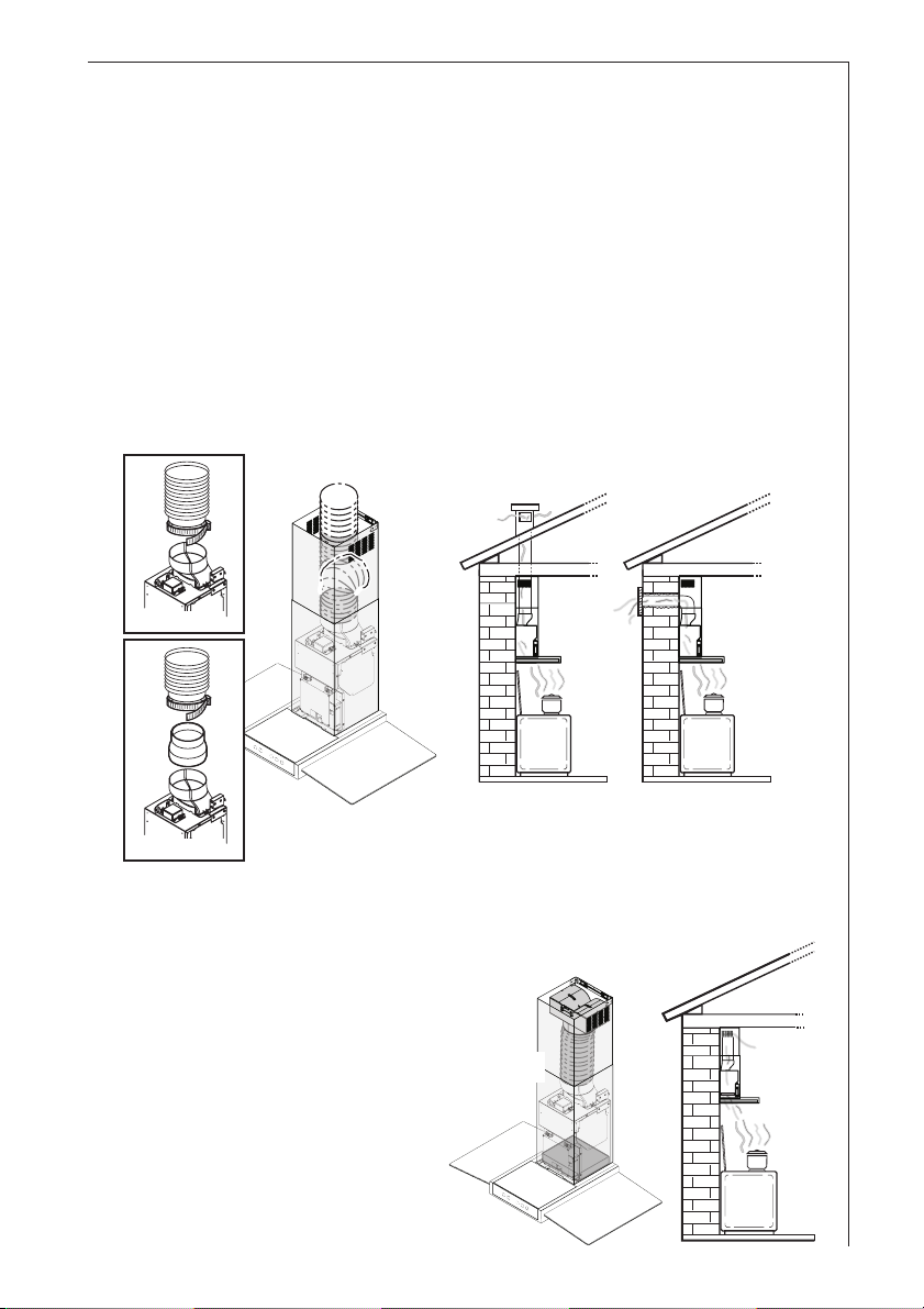
Extraction mode
• In this mode fumes are extracted to the outside via a hose
connected to the coupling ring. Fig. 1
• In order to obtain the best performance the hose should have a
diameter equal to the outlet hole.
Top
Ø 150 mm
Ø 120 mm
Coupling ring
Fig. 1
Recirculation mode
• The air is filtered through a
charcoal filter and returned
to the kitchen. Fig. 2
• You will need an original
charcoal filter for the
recirculation mode. (See
Special Accessories).
Rear
RearTop
Fig. 2
5
Page 6

Control Panel
• Best results are obtained by using a low speed for normal
conditions and a high speed when odours are more concentrated.
Turn the hood on a few minutes before you start cooking.
The hood should be left on after cooking for about 15 minutes or
until all the odours have disappeared.
The control switches are located on the unit’s front panel:
123 456
ab
1 - Mains switch, ON/OFF
Press for less than 1 1/2 seconds and the cooker hood goes into the
"stand by" position (point "b" is illuminated).
Press for more than 1 1/2 seconds and the cooker hood turns off,
ALL the controls (except the light push button) are disabled (the
display is off).
Press again for more than 1 1/2 seconds to reset the cooker hood to
"stand by".
2 - Light ON/OFF
3 - Display
4 - Start and choice of motor speed 1-2-3-1-2.........
5 - Intensive speed on/off. The Intensive speed runs for 5 minutes:
If the hood is on when the Intensive speed is activated, the hood will
revert to previous speed after 5 minutes.
If the hood is off when the Intensive speed is activated, the hood will
automatically turn off after 5 minutes.
To interrupt the Intensive speed, press button 1 or 4.
The letter P appears on the display and the remaining time (the
point “a” is flashing), if interrupted an acoustic signal is heard.
6 - Self-Timer: times all the speed levels (the point “b” is flashing), and
then the cooker hood switches off:
The self-timer is set as follows:
1st speed level 20 minutes
2nd speed level 15 minutes
3rd speed level 10 minutes
The display shows the remaining operation time, at the end of the
time an acoustic signal is heard. Depressing the push-button again
exits the function.
Should the hood or the controls fail to operate: disconnect the power
supply for at least 5 seconds. After reconnecting the power supply
wait 15 seconds and then check that the cooker hood is now
operating correctly.
6
Page 7

Grease and charcoal filter maintenance indicator
This hood is fitted with a device that indicates when it is necessary to
clean the grease filter or the charcoal filter (if the hood is used in the
recirculation version with a charcoal filter).
On delivery, the hood is not supplied with a charcoal filter, so the
saturation indicator will be disabled.
If the hood is to be used with a charcoal filter, the saturation
indicator light must be enabled as follows:
Press buttons 4 and 5 simultaneously and hold them for 3 seconds.
At first only the grease filter LED F will light up, but when the charcoal
filter LED C lights up the saturation indicator will be enabled.
To disable it: Press buttons 4 and 5 again simultaneously and hold
them for 3 seconds, until the charcoal filter LED C goes out.
Grease filter LED (F)
LED F will start to flash when it is time to clean the grease filter.
Cleaning will be necessary after 40 working hours. Always comply
with the maintenance instructions for the grease filter.
Charcoal filter LED (C)
The charcoal filter LED C will start to flash when the charcoal filter
needs to be replaced.
This operation is necessary after approximately 160 working hours.
Resetting the saturation indicator
After cleaning or replacing the filters, press button 1 for 3 seconds
until the grease filter LED F or the charcoal filter LED C stops flashing.
Warning! The resetting of the saturation indicator MUST be done in
stand-by, never disconnect the hood from the mains.
Correct ventilation
If the cooker hood is to work correctly there must be an under
pressure in the kitchen. It is important to keep the kitchen windows
closed and have a window in an adjacent room open.
7
Page 8

Maintenance and Care
Warning! Before performing any maintenance operation, isolate the
hood from the electrical supply by switching off at the connector and
removing the connector fuse.
Or if the appliance has been connected through a plug and socket,
then the plug must be removed from the socket.
Metal grease filter
• The purpose of the grease filters is to absorb grease particles
which form during cooking and it must always be used, either in the
external extraction or internal re-circulation function.
Attention: the metal grease filters must be removed and washed,
either by hand or in the dishwasher, every four weeks.
Removing the metal grease filters
• Pull the handle downwards, then remove the filter. Fig. 3.
Hand washing
Soak grease filters for about one hour in hot water with a greaseloosening cleaner, then rinse off thoroughly with hot water. Repeat
the process if necessary. Refit the grease filters when they are dry.
Dishwasher
Place grease filters in the dishwasher. Select most powerful
washing programme and highest temperature, at least 65°C.
Repeat the process. Refit the grease filters when they are dry.
When washing the metal grease filter in the dishwasher a slight
discolouration of the filter can occur, this does not have any impact
on its performance.
• Clean the inner housing using a hand hot solution only(never use
caustic detergents, abrasive powders or brushes).
Fig. 3
8
Page 9

Charcoal filter
• The charcoal filter should only be used if you want to use the hood
in recirculation mode.
• Replacing the charcoal filter
The charcoal filter cannot be washed nor regenerated.
The charcoal filter should be replaced every 4 months under
normal use.
Replacement filters are available from your local Service Force
Centre.
• Fitting - Fig. 4
Position the carbon filter inside the hood to cover the protection grill
of the motor.
Fix the filter with 2 lateral knobs.
• To remove proceed in the reverse order.
• Always specify the hood model code number and serial number
when ordering replacement filters. This information is shown on the
rating plate located on the inside of the unit.
• The charcoal filter can be ordered from your local Service Force
Centre.
Fig. 4
9
Page 10

Warning
• Failure to observe the instructions on cleaning the unit and changing
the filters will cause a fire hazard. You are therefore strongly
recommended to follow these instructions.
• The manufacturer declines all responsibility for any damage to the
motor or any fire damage linked to inappropriate maintenance or
failure to observe the above safety recommendations.
Changing the light bulbs
• Disconnect the cooker hood from the mains supply.
• Prior to touching the light bulbs ensure they are cooled down.
• Extract the lamp cover by
using a small flat
screwdriver or similar tool
as a lever. Fig. 5
• Replace the old bulb with
a new one of the same
type.
• Refit the lamp cover.
• If the light does not come
on, make sure the bulb
has been inserted in
correctly before contacting
your local Service Force
Centre.
Fig. 5
Cleaning the hood
• Clean the outside of the hood using a damp cloth and a solution of
water and mild washing up liquid.
• Never use corrosive, abrasive or flammable cleaning products or
products containing bleach.
• Never insert pointed objects in the motor’s protective grid.
• Only ever clean the switch panel and filter grill using a damp cloth
and mild washing up liquid.
• Clean all the plastic parts with a soft cloth soaked in warm water
and neutral soap.
• It is extremely important to clean the unit and change the filters at
the recommended intervals. Failure to do so will cause grease
deposits to build up that could constitute a fire hazard.
10
Page 11

Special accessories
Charcoal filter TYPE 15
Technical assistance service
You are welcome to telephone our technical assistance service (see list of technical
assistance centres) whenever you need information or in the unlikely event of a fault.
For service in Australia call 1300 650 020.
When calling, please be ready to specify:
1. The model code number
2. The serial number
3. The Product number.
This information is shown on the registration plate inside the unit behind the
grease filter.
We reserve the right to change specifications and colours as a result of our policy of
continuing technological development.
Technical Details
DD 9864 DD 9874 DD 9894
Dimensions (in cm):
Height (Extract. mode): 77-117 77-117 77-117
Height (Recirc. mode): 77-117 77-117 77-117
Width: 59,8 69,8 89,8
Depth: 45 45 45
Max. absorb. power: 215 W 215 W 215 W
Motor: 175 W 175 W 175 W
Lighting: 2x20 W(G4) 2x20 W(G4) 2x20 W(G4)
Length of the cable: 150 cm 150 cm 150 cm
Electrical connection: 220-240 V 220-240 V 220-240 V
Fuse rating: 5At 5At 5At
Mounting accessories included
2 screwdriver bits (for TORX screws)
1 deflector
1 reduction flange Ø 125-120 mm
1 chimney support
1 support bracket
5 wood-screws 5 x 45 mm (for wall mounting)
5 Wall dowels Ø 8 mm (for wall mounting)
2 screws 2,9 x 6,5 (to fix the upper chimney)
2 metal screws 3,5 x 9,5 (to fix the deflector)
11
Page 12

Electrical connection
Safety warnings for the electrician
Safety warnings for the electrician
The mains power supply must correspond to the rating indicated on
the plate situated inside the hood. If provided with a plug connect the
hood to a socket in compliance with current regulations and positioned
in an accessible area. If it not fitted with a plug (direct mains
connection) or if the plug is not located in an accessible area apply a
bi-polar switch in accordance with standards which assures the
complete disconnection of the mains under conditions relating to overcurrent category III, in accordance with installation instructions.
IMPORTANT: Before re-connecting the hood circuit to the mains
supply and checking the efficient function, always check that the
mains cable is correctly assembled.
12
Page 13

Installation
• Disconnect the hood during electrical connection, by turning the
home mains switch off.
• Remove the grease filters.
• Mark the wall with a centre line, this will aid mounting procedure
(1), position the template so that the mid line printed on the
template matches with the centre line previously drawn, the lower
side of the template corresponds to the lower side of the hood once
mounted (2).
• Make holes as indicated on the template, insert the wall dowels and
fix the support bracket with two screws into the upper holes (3).
Note: Always make the holes indicated on the template. The upper
2 are for hooking the hood up while the lower hole is for the definitive and safety fixing.
• Drill two holes Ø 8mm on the upper side close to the ceilling, fit two
wall plugs (4) and fix the chimney support G with two screws (5).
• Hang the hood (6) and adjust its position (7-8).
• Fix the hood definitively with one screw (9).
• If the hood is used in the recirculation mode, fix the deflector F on
the chimney support G with 2 screws and fit an extraction pipe (10)
to connect deflector to the outlet hole B of the hood.
In case the hood is to be used in extraction mode, then the
deflector must not be mounted and fit an extraction pipe (10) to
connect outlet hole B of the hood to the outside.
• Make electrical connection (11).
• Slide the lower section of the flue down to cover the aspiration set
until inserting it completely into the apposite housing over the hood
(12).
• Raise the upper flue and fix it above with 2 screws (13a) to flues
support bracket (13b).
• Refit the grease filter.
• Turn the mains power on again at the central electrical panel and
check for correct hood operation.
13
Page 14

11
13a
10
13a
13b
G
F
4
G
4
13b
1
5
14
6
12
6
B
7
8
9
3
2
3
Page 15

15
Page 16

LI3TPB Ed. 04/09
 Loading...