

Page 1
DD8692-M
Kamin-Dunstabzugshaube
Cappa a camino
Canopy Hood
Hotte avec cheminée
Wasemkap met schouw
Benutzerinformation
Libretto di istruzioni
Instruction Manual
Manuel d’instructions
Instructieboekje
Page 2
Dear Customer,
Please read this instruction manual carefully and particularly the chapter on “Safety” at
the beginning. In addition, you are advised to keep this manual to be able to consult it
when required and, where relevant, pass it on to any subsequent owner of the hood.
The danger triangle and/or the written warnings (Warning!, Danger!, Attention!) indi-
cate important safety information for the user or for the operating capacity of the hood,
these warnings must be strictly adhered to.
1. This symbol will guide you step by step in the use of the hood.
2. ..........
3. ..........
After this symbol additional information regarding the use of the hood will be supplied.
The clover sign indicates useful information regarding economic and ecological use of
the hood.
This manual also contains useful advice on solving certain problems. Please refer to the
chapter “Troubleshooting”. If further advice is required, please contact the two Focal
Points at any time, and you will be given the assistance you require.
We are available:
from Monday to Friday from 8.00 a.m. to 8.00 p.m.
Saturday from 10.00 a.m. to 2.00 p.m.
An advisor will be available to answer your questions regarding the equipment and use
of the hood. Naturally, we will also take note of your requests and suggestions. Our aim
is the continual improvement of our products and services, to the benefit of our customers.
For technical assistance, please contact your nearest CUSTOMER SERVICES (the
addresses and telephone numbers are provided in the chapter, “Customer Service
Centres”). See also the chapter, “Service”.
Printed on recycled paper. He who thinks ecologically, acts accordingly ...
35
Page 3
Instructions for use
INSTRUCTIONS FOR USE
Safety
The safety requirements of this hood conform to recognised technical regulations and to
the safety laws governing the appliance. However, as manufacturer of the hood, our
company considers it advisable to provide the following customer safety information.
Electrical safety
• Where the hood is to be permanently connected to the electrical supply, the electrical
installation must be carried out exclusively by an authorised electrician. This warning
should be strictly adhered to ensure the validity of the guarantee.
• Repairs should be carried out exclusively by specialised technicians. Poor workmanship
and inadequately carried out repairs can be extremely dangerous. We recommend you
contact our Customer Services or your usual dealer for all repair work.
Safety during use
• Overheating may cause the hood to ignite.
We therefore recommend that you observe the following warnings:
- never do flambé cooking under the hood.
- lit burners should always be covered when the hood is in use. In the case of gas oil, gas
and coal cookers, naked flames must be avoided at all times.
- never leave frying pans unattended during use: overheated fats and oils ignite easily.
The danger of ignition is particularly high if the oil is dirty.
• Before carrying out any kind of work on the hood, even the simple replacement of a
bulb, the apparatus must be isolated from the electrical supply (pull out the plug, remove
the fuse from the fuse box or switch off at the mains).
• Always adhere to the recommended cleaning or filter replacement intervals to avoid the
risk of fire when the filters are saturated with grease.
Safety during cleaning
For safety reasons it is not permitted to clean the hood with steam spray or high pressure
devices.
Disposal
Disposal of the packaging
• All parts of the packaging are recyclable. The plastic film wrapping and the foam plastic
items are clearly marked. The packaging material and any used equipment should be
disposed of correctly.
• Respect the national and regional regulations and the markings on the materials
(separation of the materials, differentiated collection, collection points for recyclable
materials).
Warnings on disposal
• The hood should not be disposed of with household waste.
• Information regarding collection dates or on the collection points can be requested from
the local refuse collection departments or from the town hall.
• Warning! Used appliances should be deactivated before being disposed of. The power
cable should be removed (after removing the plug or, in the case of a permanent
connection, after having the hood disconnected by a technician).
36
Page 4
Instructions for use
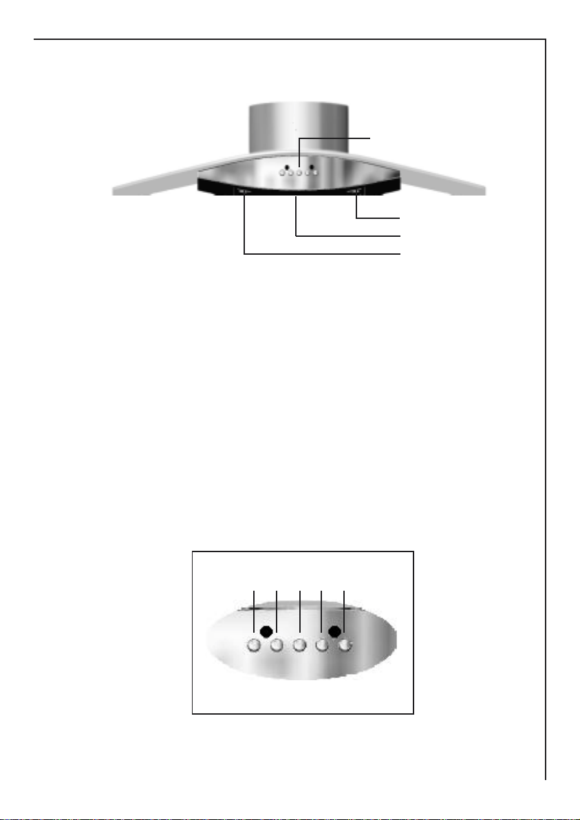
Description of the hood
Control panel
Lighting
Metal grease filter
Lighting
Control panel
Key L = Turns the lighting system on and off
Key V1 = Turns the motor on/off and the saturation metal grease filter alarm
(LED starts to flash)
Key V2 = Second speed
Key V3 = Third speed
Key I = Intensive speed with timed stoppage and saturation charcoal filter
alarm (LED starts to flash). Suitable to deal with maximum
vapour emission, this turns off automatically 10 minutes after
starting operation.It can be disabled by pressing the key I .
V1 V2 V3 IL
37
Page 5
Instructions for use
MAINTENANCE
Constant maintenance guarantees proper operation and longterm reliability. Particular
attention should be paid to the metal grease filters and, for recirculation hoods only, to
the activated charcoal filters. The appliance is equipped with a system that indicates
automatically when it is time to carry out maintenance operations.
Metal grease filter
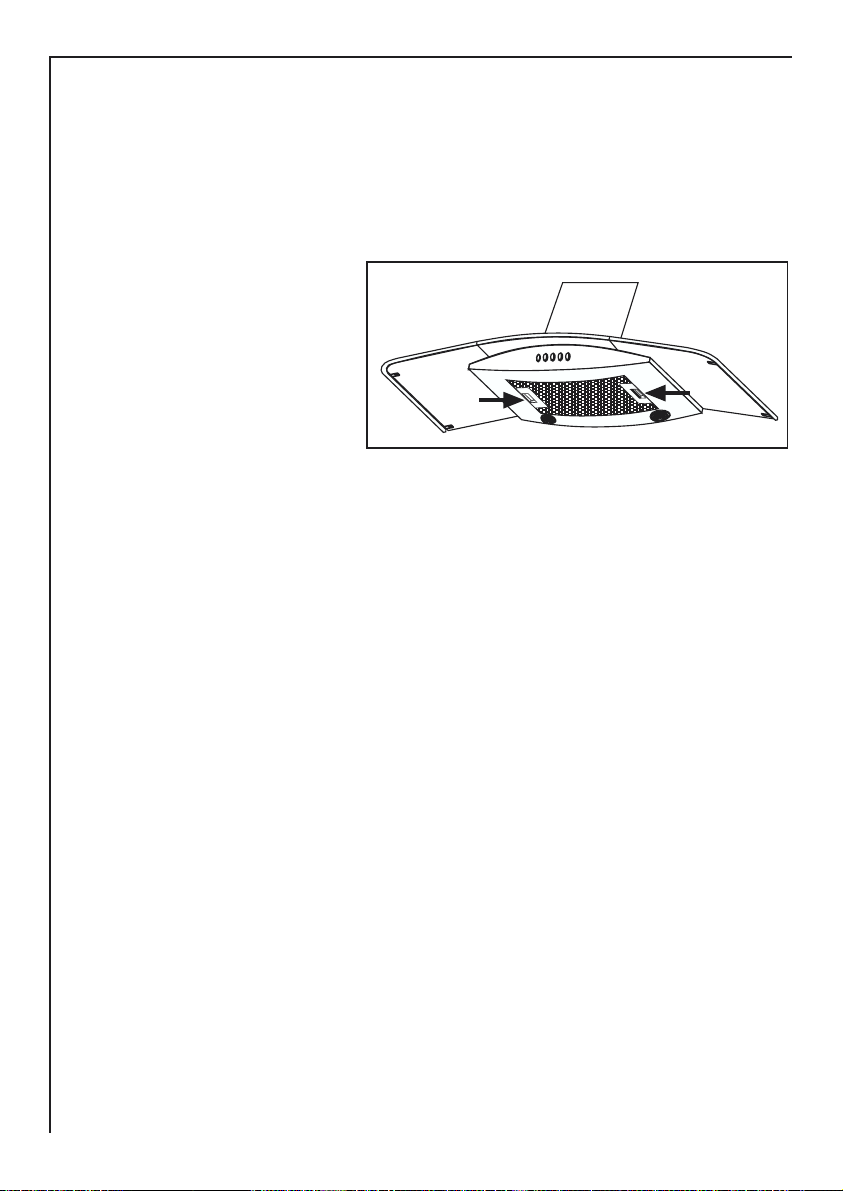
• Cleaning
This filter must be washed when
LED V1 starts to flash, or at the
most once every 2 months, using
a normal household detergent; its
compact size also enables it to
be washed in a dishwasher.
• Replacement
Remove the filter, pushing the
handle towards the rear of the
hood. When replacing, ensure
that the handle faces outwards.
• Enabling the alarm signal
The hood is already set up to trigger an alarm indicating saturation of the metal grease
filters,so this function does not need to be enabled.
• Resetting the alarm signal
To turn the alarm signal off, proceed as follows:
- Turn off the Lights L and the Suction Motor V1;
- Press the Speed V3 for at least 3 seconds, until the Leds flash in confirmation. In any
case the saturated filters alarm will only come into operation when the suction motor is
turned on.
ATTENTION - There could be a possible fire hazard if the filters are not replaced
according to these instructions.
S07_06
Active carbon filter
• Operation
The activated charcoal filter is only fitted in recirculation type hoods.It will retain odours
until it becomes saturated. It cannot be washed or regenerated, and must be replaced
when the Intensive Speed LED I starts to flash, or at least once every 4 months of
use. Attention: in recirculation type hoods the V1 Motor LED may start to flash as well as
the Speed + V3 LED. This indicates that as well as replacing the activated charcoal
filter, it is also necessary to perform maintenance operations on the metal grease filters
(see paragraph Metal grease Filter).
38
Page 6
Instructions for use
• Replacing
Take off the metal grease filter and
remove the activated charcoal
filter from its housing by turning
the clips provided. Fit the new
activated charcoal filter and
replace the metal grease filter.
• Enabling the alarm signal
S07_31
In recirculation type hoods the
saturated filters alarm must be
enabled as indicated below:
• Turn off the lights L and the Suction Motor V1;
• Press and hold the button V3 for at least 10 seconds, until the Leds start to flash.
Note the number of flashes:
- 2 flashes of the LED Activated charcoal filter saturation alarm ENABLED
- 1 flash of the LED Activated charcoal filter saturation alarm DISABLED
• Resetting the alarm signal
To turn the alarm signal off, proceed as follows:
- Press the button V3 for at least 3 seconds, until the Leds flash in confirmation. In any
case the saturated filters alarm will only come into operation when the suction motor is
turned on.
ATTENTION - There could be a possible fire hazard if the filters are not replaced
according to these instructions.
Lighting
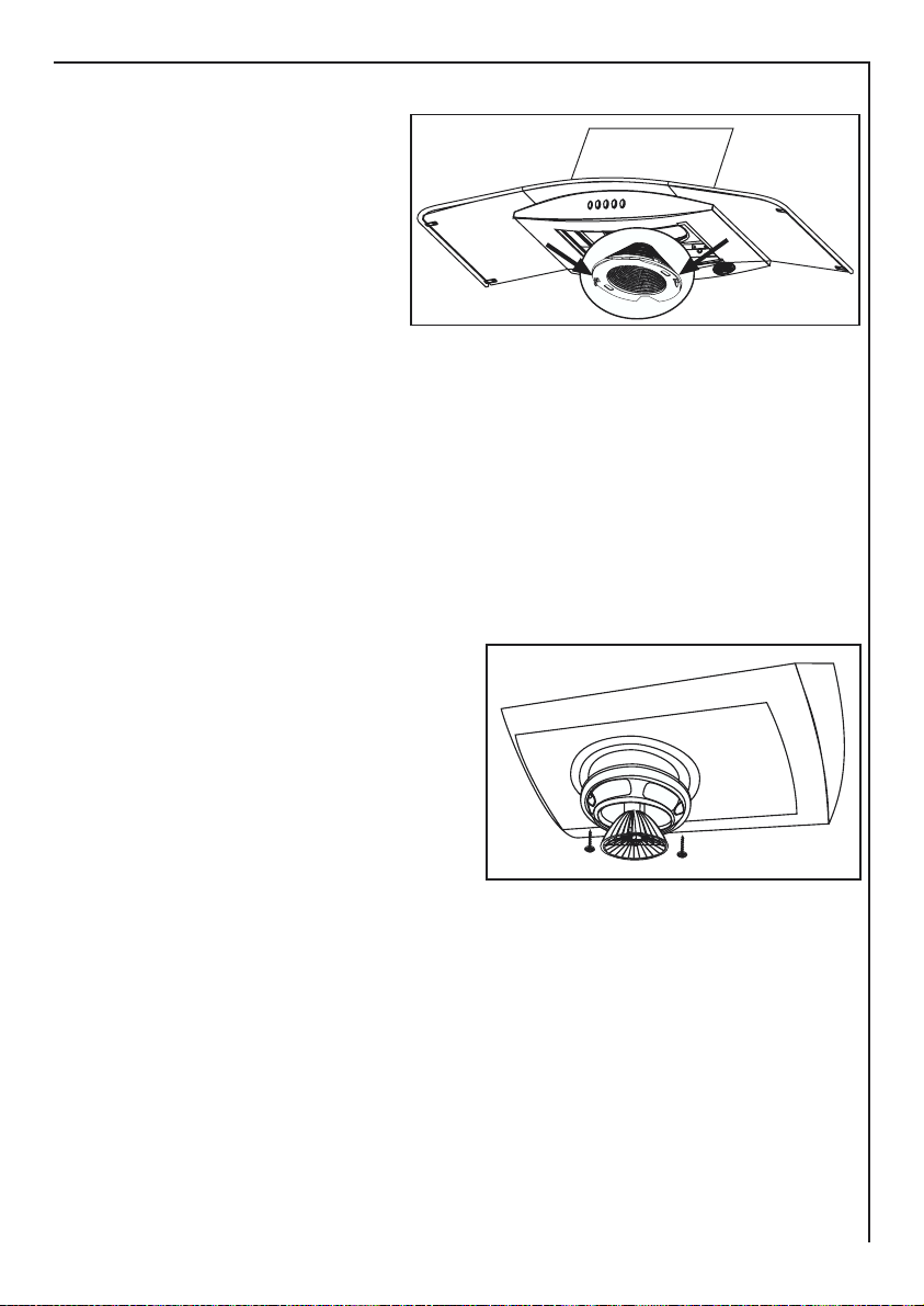
1 - It consists of 2 20 W-halogen spotlights.
2 - Replacement
Remove the two screws that lock the metal
ring, take the spotlight out of its holder by
pulling slightly. When replacing, make sure
that both pins are well inserted in the holder
seat.
S07_28
Special accessories
Wall housing MKZ 125 Serial no. 610 899 004
Height x width in mm
External dimensions 250 x 220
Wall aperture 185 x 210
Outlet duct ABS 120 Serial no. 942 118 611
Ø 120 mm aluminium
Outlet duct ABS 125 Serial no. 942 118 612
Ø 125 mm aluminium
39
Page 7

Instructions for use
Installation Instructions
Safety warnings for the electrician
Electrical connection
Voltage 230 V ~ Connect using:
• a fixed power cable with a Schuko plug (European type) or
• a fixed connection (by an authorised electrician).
Fixed connection
• Where a fixed connection is necessary, an authorised electrician, registered with the
competent electrical authority, must carry out the work.
• For the installation, a single-pole switch with a minimum distance between the contacts
of 3 mm must be used, to enable the appliance to be isolated from the mains.
This function can be carried out, for example, by using automatic circuit breaker switches,
fuses (the fuses should be removed from the fuse box), and contact breaker switches.
Safety Warnings for the kitchen fitter
Minimum Distance from the hob
• When fitting the hood the following minimum distances from the upper edge of the cooking
hob to the lower edge of the hood must be respected:
- electric hobs: 650 mm
- gas hobs: 650 mm
- coal /gas-oil cookers: 700 mm
Air outlet
For the air outlet the following regulations must be observed:
• The discharged air should not be directed into flues or outlet ducts for combustion gases.
• It is not permitted to direct the discharged air into a duct that is used for ventilation of
areas in which combustion apparatus is installed.
• In case of the discharged air being emitted into a flue or outlet duct for combustion
gases which is no longer used, it is recommended that you consult a competent heating
engineer first.
• The hood can only operate at optimum efficiency if the following rules are respected:
- use short straight sections for the outlet duct.
- keep bends in the discharge ducting to a minimum.
- do not use ducts with sharp curves, use slightly curved sections.
- use large diameter ducts of large diameters where possible.
• Non adherence to these basic rules will compromise hood performance and increase
the noise levels produced.
Air Inlet
• A sufficiently large ventilation hole must be provided, of dimensions approximately equal
to the outlet hole.
40
Page 8

Instructions for use
Operation of hoods and appliances connected to a chimney
in the same room
• Regional building regulations require that the use of hoods in rooms where combustion
appliances are installed and connected to a chimney, for example coal, gas-oil, gas
heaters, etc., be subject to specific restrictions.
• The Regulations on combustion installations requires that these rooms must not exceed
a maximum negative pressure of 0.04 mbar.
• Safe use of hoods in conjunction with appliances connected to a chimney assumes that
the area and/or the house (combined recirculation system) is ventilated from the exterior
via an aperture of suitable dimensions, of approximately 500-600 cm
negative pressure during the use of the hood.
• In case of doubt consult an authorised heating engineer or the local building authorities.
• In rooms where combustion appliances are not installed the following rule should be
applied: “Ventilation hole of dimensions not exceeding those of the outlet hole“, an aperture of dimensions exceeding 500-600 cm2 may compromise performance of the suction
unit.
2
, in order to avoid
Technical Specifications
Working Dimensions
Width 900 mm.
Depth 500 mm.
Height 680-1080 mm.
Power cable length 200 cm.
Weight 19,4 Kg
Connected power
Total connected power 180 W
Motor 1 x 140 W
Lighting 2 x 20 W
Voltage 220 V ~
Discharge System Ø 120 mm /125 mm
Directives, regulations, instructions
This hood complies with the following European Directives:
• EEC 73/23 dated 19.02.1973 (low voltages)
• EEC 89/336 dated 03.05.1989 (electromagnetic compatibility, including
the modification directive EEC 92/31)
41
Page 9

Instructions for use
Installation
Fitting Materials / Accessories
1 connector flange Ø 120 mm F
1 reduction flange Ø 120-125 mm
1 side connector flange R
1 ventilator fixing bracket S
1 plastic guard D
1 cable clamp
3 dowels T
2 plastic caps Ø 11 mm
1 fitting support
1 transparent seal for chimney connection
4 canopy hood body/chimney fixing screws
2 O rings to hang the hood
1 screw V to fix the bracket to the wall
1 screw for fixing the bracket to the ventilator
2 screws 3.5x9.5 K to fix the fitting support
Fitting Instructions
42
C
73
898
A
Ø 270
195
65
92
Ø 200
min. 650
450
450 - 850
180
500
Page 10

Instructions for use
Preparations for the outlet duct
Before fitting the hood the fixing holes must be drilled and a hole must be made through
the external wall for installation of the wall housing (air outlet/inlet).
Preparations for the wall housing/Hole through the ceiling
If cooking vapours are to be discharged into the open-air through the external wall, a
telescopic wall housing must be used (available as a special accessory).
For discharge System Ø 120 mm /125 mm:
MKZ 125 ( with air outlet/inlet) Serial no. 610 899 004
43
Page 11

Installation
INSTALLATION
The versatility of the ducting fan unit on this hood enables it to be installed in one of two
different ways:
1 - Air outlet directed towards the wall.
2 - Air outlet directed to the right or left.
For correct installation of the hood, please proceed in the following stages:
4.1 - Selection of the type of installation
4.2 - Installation of the hood canopy C
4.3 - Installation of the chimney A
4.4 - Ducting or recirculation fitting
4.5 - Electrical connection and testing
Selecting the type of installation
1 - Air discharge towards the wall (fig.2)
2-Side air discharge, Left or Right (fig.3a-b).
S07_03
S07_04
3a 3b
4a 4b
R R
2
Installation of the hood canopy C
1 - Drilling the wall
a) Using the cardboard template
provided, mark on the wall the
centres of holes 1 for fixing of the
hood canopy C. The centre of hole 2
for fixing the chimney, (fig.4a) air
outlet towards the wall, (fig. 4b-c) air
outlet to the right or left hand side,
must be marked at a distance X from
Z
the line between holes 1, obtained
by measuring the extension of the
chimney required for installation, plus
13 mm X=Z+20-7. Using a Ø 8 mm
40
650
drill bit, drill the points marked in this
way.
b) When installed with the air outlet
directed towards the wall (fig.4a), it
A08_05
will be necessary to drill an air
ducting opening, measuring Ø120 or 125 mm, according to the diameter of the flange F
provided.
120
ø
7
2
1 1
100
100
ø150
X
1
18
ø 8
105
2
1
4a 4b 4c
105
2
1
1
44
Page 12

L = 44 mm
V
S
2
A08_07
S07_08
Installation
2 - Fitting the fixing elements
a) Insert the rawl plugs provided into holes 1 and 2.
b) Fit the eye bolts O (fig.5).
c) Fix the wall bracket S in hole 2 using the screw V provided
(fig.6).
3 - Fitting the hood canopy C to the wall
a) Remove the metal grease filter (see the paragraph on
Maintenance).
b) Fit the support rod B using the two screws K (3,5x9,5)
provided (fig. 7).
c) Hook the hood canopy C to the eye bolts O fixed in holes 1
(fig. 8).
d) Adjust the support rod B so that it pushes against the wall
(fig. 9).
e) Adjusting position (fig. 10). There are two adjustable hooks
7
B
K
8
O
O
A08_08
S07_09
at the rear of the
hood, which can be used to adjust its position as follows:
• Turn the screws L until the position of screws N coincides
with the lower access holes.
• Turn the screws N to adjust the vertical and horizontal
position of the hood.
• Lock the screws L to fasten the hood against the wall.
• Insert the plugs T provided in the holes giving access
N
to screws N.
Installation of the chimney A
No matter which type of installation is being used,
T
any wooden shelves in the area where the hood is to
be fitted must first be removed, drilled and later
replaced.
A08_11
1 - Drilling the shelves:
a) Using the cardboard template provided, and
taking hole “B” as a point of reference, drill the
11
shelves along the central axis to allow the
passage of the chimney. The chimney must be
inserted into the shelves before it is fixed to the
hood canopy C (fig.11).
5
1
O
A08_06
6
O
A08_10
B
9
L
L
N
T
L
N
10
45
Page 13

S07_14
Installation
2 - Direction and position of the ducting fan unit
a) The hood is normally supplied with the air outlet directed towards
the wall (fig. 2), if it is to be installed with the air outlet directed to
the right or left (fig. 3a-b), it will be necessary to change the direction
of the ducting fan unit, proceeding as follows:
• Unscrew the screws U (fig. 12);
• Turn the ducting fan unit 60° to the right or left;
• Replace the screws U.
b) The ducting fan unit air outlets must be arranged according to the
type of installation to be carried out.
• Air outlet directed towards the wall (fig. 2).
• Remove the plastic frame from the air outlet (fig.14).
• Remove the plug from the upper part of the ducting fan unit
(fig.13), as it is not possible to insert the flange F with the plug in
place.
• Fit the flange F Ø120 mm (fig.16), replace the plug.
• Air outlet directed to the right or left hand side (fig. 3a-b).
• Remove the four screws fastening the plastic frame, as
shown in fig. 14.
• Fit the ducting spigot R (fig.17) and replace the four screws
removed as above.
3 - Fixing the chimney
a) Loosen the screws M fixing the two parts of the chimney
and pull the inner
section I (fig.18)
almost all the way
out. Remove the
protective film P.
b) Rest the lower
S07_16
section of the
chimney in its
housing on the top of
15
the hood canopy.
Lower the ducting fan unit until it reaches the
wall bracket S and fix it using the screw H
provided (fig.19). Fit the cover D (provided) on
the wall bracket S (fig.20).
17
S07_19
12
U
U
A08_14
13
S07_22
14
16
R
46
I
M
A08_20
S
P
18
S
A08_21
H
19
Page 14

c) Fix chimney stack A to the hood unit C using four of the screws
D
A08_22
provided E (fig.21).
d) Insert the transparent seal Q (provided), so as to eliminate any
play between the two parts of the chimney (fig. 22). Lock the
screws M.
e) Remove the support rod B.
Installation
20
Ducting or recirculation fitting
1 - Ducting fitting.
This is possible for all forms of installation:
a) Connect the air outlet to the external ducting
system.
b) Remove the activated charcoal filter (if there is
one) inside the hood canopy (see Maintenance).
2 - Recirculation fitting
This is only possible with the air outlet directed
upwards. Fit the venting grille G onto the air outlet (Fig. 23).
The activated charcoal filter should be fitted inside the hood
canopy after connection to the power supply.
A08_23
E
E
Connection to power supply and checking of
good working order
1 - It is absolutely necessary to follow the warnings 3.2, 3.3 and 3.4 of
paragraph 3, concerning safety measures.
2 - Loosen the two locking screws and remove the metal cover (fig.24).
Connect the hood connection to the engine connection (fig.25a).
Correctly place the connectors under the cover and tighten the two
locking screws (fig. 25b).
3 - Once electrical connection has been carried out, check that lights,
engine and change of speed work
4 - Fit the antigrease filter (see Maintenance).
E
E
21
22
Q
Q
A08_24
G
S07_24
24
23
25a
25b
S07_34
47
Page 15

Customer Service Centres
CUSTOMER SERVICE CENTRES
Dear Customer,
The AEG Hausgeräte Customer Service Department is decentralised to offer you a quick
and reliable service everywhere. By calling the following free phone number:
0800 234 73 78
You can speak to one our specialists or associates in charge of technical assistance.
To order spare parts please contact our switchboard on the following number:
0180 5 00 10 76
For freezer breakdowns or breakdowns in the freezer compartment of your fridge or in
your heating system, an emergency service is available, which can be reached on
Saturdays or Sundays on the free phone number: 0800 820 20 00.
Yours faithfully,
Your AEG Customer Services
In addition, you can visit one of our Service Centres.
01099 Dresden Industriegelände,W.-Hartmann-Straße
04356 Leipzig Walter-Köhn-Straße 4c
07548 Gera* Südstraße 11
08066 Zwickau* Talstraße 24
09117 Chemnitz* Rosmarinstraße 4
14482 Potsdam-Babelsberg Wetzlarer Straße 14-16
22525 Hamburg-Bahrenfeld Holstenkamp 40
28208 Bremen Emil-von-Behring-Straße 3
30179 Hannover Wiesenauer Straße 13
34123 Kassel-Bettenhausen Lilienthalstraße 150
35745 Herborn-Burg Junostraße 1
41541 Dormagen-St. Peter Sachtlebenstraße 1
44805 Bochum-Gerthe Josef-Baumann-Straße 37
46562 Voerde* Friedrich-Wilhelm-Straße 22
48165 Münster* Zum Kaiserbusch 1
49084 Osnabrück* Pferdestraße 23
52068 Aachen* Auf der Hüls 197
56068 Koblenz* Rheinstraße 17
57072 Siegen* Sandstraße 173
60326 Frankfurt Mainzer Landstraße 349
66115 Saarbrücken-Malstatt* Ludwigstraße 55-57
*) Here, one of our technical assistance associates will be pleased to assist you.
48
Page 16

Customer Service Centres
67663 Kaiserslautern* Pariser Straße 200
68309 Mannheim-Käfertal Heppenheimer straße 31-33
71034 Böblingen-Hulb Dornierstraße 7
76185 Karlsruhe-Mühlburg Neureuther Straße 5-7
79108 Freiburg* Tullastraße 84
80634 München-Neuhausen Arnulfstraße 205
86159 Augsburg* Piccardstraße 15a
87437 Kempten* Brodkorbweg 22
88213 Ravensburg* Henri-Dunant-Straße 6
90429 Nürnberg Muggenhofer Straße 135
91788 Pappenheim* Neudorf 79
92260 Ammerthal* Nikolausstraße 2
93059 Regensburg* Im Gewerbepark B54
94032 Passau* Kühberg 1
95038 Hof* Pinzigweg 49
97078 Würzburg* Versbacher Straße 22a
99096 Erfurt* Arnstädter Straße 28
*) Here, one of our technical assistance associates will be pleased to assist you.
03058 Kickebusch 03222 Groß Klessow
06429 Wispitz 06896 Wittenberg-Reinsdorf
15517 Fürstenwalde 16515 Oranienburg
17039 Ihlenfeld 18055 Rostock
18069 Rostock 19057 Schwerin
24354 Rieseby 25770 Hemmingstedt
25980 Westerland/Sylt 26639 Wiesmoor
27726 Worpswede 30900 Wedemark
32825 Blomberg 34497 Korbach
36043 Fulda 39114 Magdeburg
49377 Vechta 63906 Erlenbach
74549 Wolpertshausen 78244 Bietingen
84307 Eggenfelden 87549 Rettenberg
89542 Herbrechtingen 99819 Ettenhausen
49
Page 17

Service
SERVICE
The chapter “Troubleshooting“ gives a table of simple problems that you may be able to
solve without assistance. Always consult this table before calling for technical assistance.
Technical Problems
For technical problems contact your Customer Service Centre (the addresses and
telephone numbers are listed in the chapter “Customer Service Centres”). We advice
customers to prepare the telephone call carefully in advance to facilitate diagnosis and
the subsequent decision regarding whether or not technical intervention is necessary.
Some important points to describe are the following:
• How did the problem manifest itself?
• In what circumstances did the problem manifest itself?
Before making the telephone call please make a note of the following information printed
on the appliance rating plate:
• PNC number (9 digits),
• F-No number (8 digits).
The rating plate is located on the interior of the hood and can be accessed after removing
the metal grease filters.
We recommend you make a note of these numbers on this page, so that they are ready
to hand.
PNC ... ... ...
F-No ... ... ...
In what circumstances are you liable for expenses during the guarantee period?
• If the problem could have been solved by the customer, based on the indications provided
in the table on “Troubleshooting”,
• If the technician had to make more than one journey because detailed information was
not supplied to him before the intervention and he therefore had to procure replacement
parts later, for example. These repeated journeys can be avoided if the telephone call is
prepared carefully in advance, as described above.
AEG Hausgeräte GmbH
Postfach 1036
D-90327 Nürnberg
http://www.aeg.hausgeraete.de
@ Copyright by AEG
50
Page 18

83
Page 19

436002473_01 - 050119
 Loading...