

Page 1
Mixed fuel cooker
A
INSTRUCTION BOOK
CKG5060W
CKG5060S
U
Page 2

2
Page 3

Important Safety Information
These warnings are provided in the interest of safety. You MUST read
them carefully before installing or using the appliance.
Keep this instruction book for future reference and ensure it is passed on
to any new owner.
Installation
• The work of installation must
be carried out by competent and
qualified installers according
to the regulations in force.
• The appliance must be installed
at a minimum distance of 50 cm
from curtains or other combustible
material.
• Any modifications to the domestic
electric mains, which may be
necessary for the installation of the
appliance, should only be carried
out by qualified electrician.
• This cooker is heavy. Take care
when moving it.
• Remove all packaging before using
the cooker.
• Ensure that the electrical supply
complies with the type stated
on the rating plate, located
near the gas supply pipe.
• It is dangerous to modify, or
attempt to modify, the
characteristics of this appliance.
• This appliance cannot be
positioned on a base.
• If the supply cord is damaged, it
shall be replaced by a special
cord or assembly available from
Authorised Electrolux Service
Centre.
• The NON-TIP DEVICE must be
fitted according to instructions to
prevent the cooker from tipping,
for example by a child climbing
onto the open oven door.
Child Safety
• This appliance has been designed
for use by adults. Supervise
children to ensure they do not
attempt to play with it.
• This appliance is not intended for
use by young children of infirm
persons unless they have been
adequately supervised to ensure
they can use the appliance
safely.
• The cooker gets hot when it is in
use and retains heat for a long
period after use. Children should
be kept away until it has cooled.
• Children can also injure
themselves by pulling pans or
pots off the cooker, they should
be supervised at all times to
ensure their safety.
• Burners, plates, grills and pans
remain hot for a long time after
being switched off. Supervise
children at all times when in use
paying attention that they do not
touch surfaces or remain in the
vicinity of the appliance when in
use or when not completely
cooled.
During use
• This cooker is intended for domestic
cooking only. It is not designed for
commercial or industrial purposes.
• This appliance is not connected to
a combustion products evacuation
device. It shall be installed and
connected in accordance with
curr e n t i n s t a l l a t i o n regulations.
3
Page 4

Particular attention shall be given
to the relevant requirements
regarding ventilation.
• When in uses a gas cooker will
produce heat and moisture in the
room in which it has been
installed. Ensure there is a
continuous air supply, keeping air
vents in good condition or
installing a cooker hood with a
venting hose.
• Ensure that air can circulate
around the gas appliance. Poor
ventilation can produce a lack of
oxygen.
• Do not use this cooker if it is in
contact with water. Do not operate
the cooker with wet hands.
• Always grill with the oven door
closed.
• The grill pan will become hot
during use, always use oven
gloves when removing or
replacing a hot grill pan.
• During use the appliance
becomes hot. Care should be
taken to avoid touching heating
elements inside the oven.
• DO NOT store or use gasoline or
other flammable vapours, liquids
or items in the vicinity of this or
any other appliance.
• Do not spray aerosols in the
vicinity of this appliance while it
is in operation.
• To facilitate ignition, light the
burner before placing the pan on
the grill.
• After having lit the burner check
that the flame is regular.
• Always lower the flame or turn it
off before removing the pan.
• Unstable or deformed pans
should not be placed on the
burners in order to avoid
accidents caused by upsetting or
boiling over.
• Ensure the control knobs are in
the ‘OFF’ position when not in use.
• When using other electrical
appliances, ensure the cable
does not come into contact with
the hot surfaces of the cooker.
• Unstable or misshapen pans
should not be used on the hob
hotplates as unstable pans can
cause an accident by tipping or
spillage.
• Never leave the cooker
unattended when cooking with
oil and fats.
• This cooker should be kept
clean at all times. A build-up of
fats or foodstuffs could result in
a fire.
• Only clean this oven in
accordance with the instru ctions.
• In case of repairs, do not attempt
to correct yourself. Repairs
carried out by unqualified persons
can cause damage. Contact the
nearest Assistance Centre and
use only original spare parts.
• WARNING – Ensure that the
appliance is switched off before
replacing the lamp to avoid the
possibility of electric shock.
• Always stand back from the
oven when opening the oven
door, to allow any build-up of
steam or heat to release.
Where this appliance is installed
•
in marine craft or in caravans, it
shall NOT be used as a space
heater.
4
Page 5

• Always ensure that the oven vent,
which is located at the centre back
of the hob, is left unobstructed to
ensure ventilation of the oven
cavity.
• Perishable food, plastic items and
aerosols may be affected by heat
and should not be stored above the
cooker.
• Before maintenance or cleaning
disconnect the appliance and allow
cooling.
• Never use steam or high-pressure
steam cleaners to clean the
appliance.
• Do no store flammable materials
(e.g. aerosols, plastic aprons,
paper baking sheets etc) in the
warming drawer, it is only intended
for warming of plates and baking
trays.
• Be careful when removing items
from the warming drawer, as they
may be hot.
Service
• This cooker should only be
repaired or serviced by an
authorised Electrolux Service
Engineer and only genuine
approved spare parts should be
used.
Your safety is of paramount
importance. Therefore, if you are
unsure about any of the meanings
of these WARNINGS, contact the
Customer Care Department.
These instructions are only valid
in the country whose symbol
appears on this instruction’s
cover.
This product should not be treated
as household waste. Instead it
should be handed over to the
applicable collection point for the
recycling of electrical and
electronic equipment. By ensuring
this product is disposed of
correctly, you will help prevent
potential negative consequences
for the environment and human
health, which could otherwise be
caused by inappropriate waste
handling of this product. For more
detailed information about recycling
of this product, please contact your
local city office, your household
waste disposal service or the shop
where you purchased the product.
Environmental Information
• After installation, please dispose of
the packaging with due regard to
safety and the environment.
• When disposing of an old
appliance, make it unusable, by
cutting off the cable.
5
Page 6
Contents
Instructions for the Installer
Technical features
Location
The safety equipment
Installation
Adaptation to different type of gas
Electrical connections
Instructions for the User
Use and care
Use of appliance
Before the first use of the oven
Electric oven
Oven function control knob
Using the Conventional Oven
Hints and Tips
Grilling
Using the Fan Oven
Defrosting
Oven Cooking Chart
Roasting/Grilling Chart
Using the Hob
Maintenance and Cleaning
Oven bulb replacement
Something Not Working
Electrolux Warranty
7
8
9
11
13
16
18
19
19
20
20
21
21
22
22
23
24
25
26
30
33
34
36
Guide to Use the Instructions
The symbols below will guide you when
reading the instruction book
Safety instructions
Step by Step Operation
Advice and recommendations
Environmental Information
6
Page 7
Instructions for the Installer
Technical features
Dimensions Height
Width
Depth
Oven Capacity
900 mm
500 mm
600 mm
45 l
Hob
Oven Top element
Supply Rated voltage
Accessories Oven grid (2 pieces)
Natural Gas
Front Left Semi-rapid 7.0 6.5
Back Left Semi-rapid 7.0 6.5
Front Right Rapid 10.5 10.5
Back Right Aux 4.2 4.0
Total 28.7 27.5
Bottom element
Grill element
Convection fan
Light in the oven
Cleaning
Total oven rating 1960 W
Rated frequency
Roasting tray + roasting grid
Total cooker rating
This appliance is manufactured
according to the following EEC directives:
73/23/EEC; 90/683 EEC; 89/336/EEC;
93/68/EEC; 90/396 EEC, current edition.
(1.00kPa)
U-LPG,
(2.60kPa)
1000 W
925 W
1925 W
60 W
Lamp 25W type E14
manual
230-240 V
50 Hz
1960,6 W
7
Page 8
Location
Qualified tradespersons must
carry out installation work on the
cooker. The cooker is heavy.
Certain edges and corners, which
will not normally be exposed, may
be sharp. USE GLOVES when
mov ing the cooker.
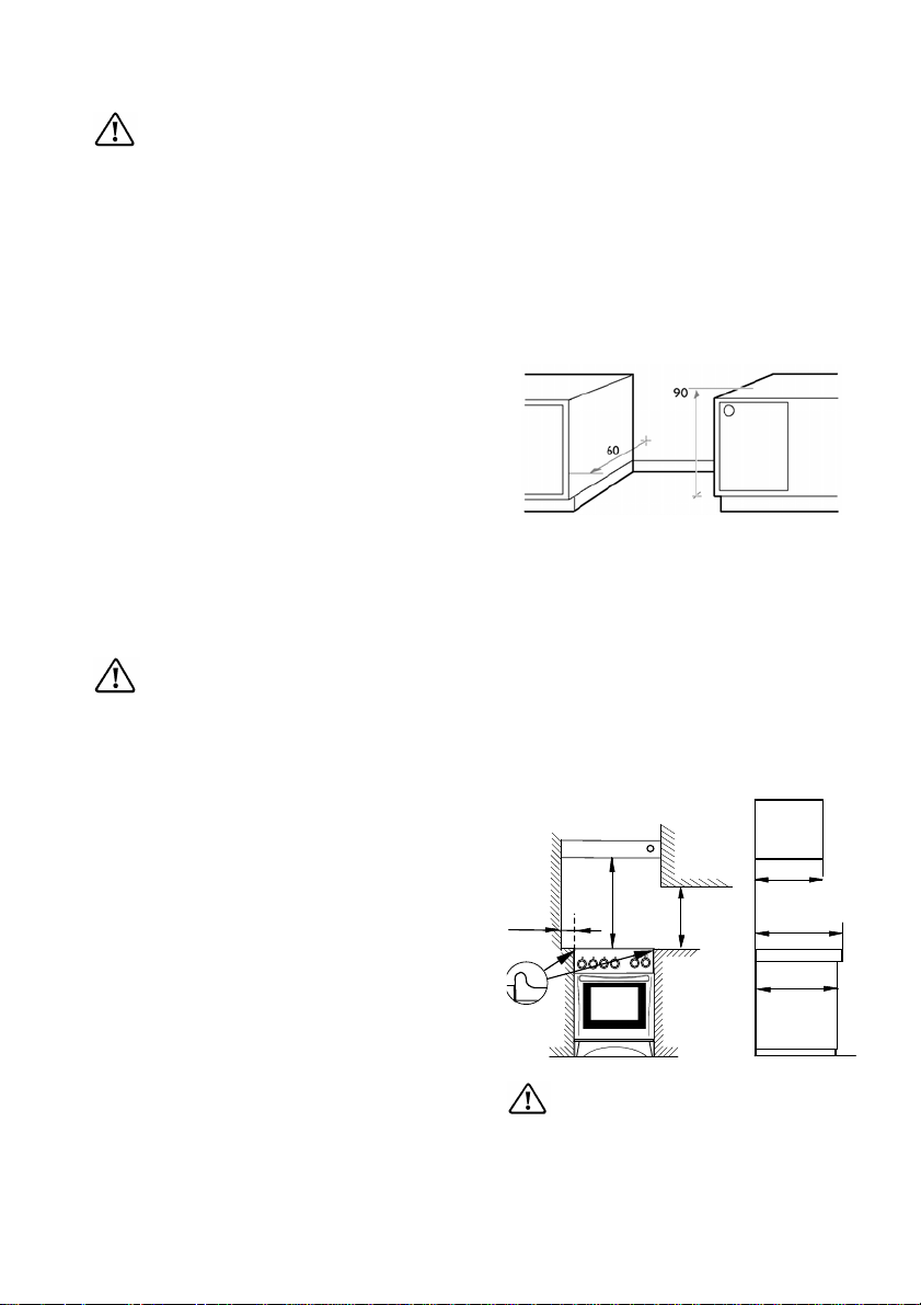
Before installing the cooker, you
should check that its dimensions
correspond to the rest of your kitchen
units. Measure the height of the
worktop from floor to top surface of
the worktop, and the cooker depth
from the wall to the front edge of the
cooker (see picture). The cooker
must also be installed in conformity
with the following standards.
If a 10A power socket or hard wiring
is required for installation, a licenced
electrician must install it.
Carry out installation as
described in the Installation
Requirement chapter – paragraph
2.4 of AG101-2000.
Gas installation must be carried out by
a qualified gas fitter in accordance with
AG101-2000. Choose a location fr ee of
draughts and open doors and clear of
combustible materials or other fire
hazards such as curtains, etc.
The location should ensure
convenience of operation and service.
Any adjacent cabinets or walls must
not exceed the cooker’s sides height
(see fig.).
The cooker may be located in a
kitchen or dining room, but not in a
bathroom or shower room. The
levelling feet fitted to the appliance
can be adjusted to achieve a nominal
height to hotplate of 900mm + 10mm.
8
400
max
150
690
500
min
min
570
The cooker should be
installed only on the floor, it is
not suitable for installation on a
base.
600
Page 9
The safety equipment
Leveling the cooker
The appliance is provided with
adjustable small feet placed in the
back and front corners of the base.
Never pull the appliance by the oven
handle.
By adjusting the small feet it is
possible to change the height of the
appliance so as to ensure a better
leveling with other surfaces and a
uniform distribution of the liquids
contained in pans or pots.
To check whether the cooker is level,
use a spirit level on the hob
surround. Check the level first front
to back and then side to side.
Non-tip device
When installing the cooker it
is compulsory to install the nontip device. The non-tip device
should be fitted, to prevent the
cooker from tipping if subjected to
an abnormal loading, for example
by a child climbing on to an open
oven door. The non-tip device can
only provide protection when the
cooker is pushed into its normal
position.
Before fitting the non-tip device, make
sure the cooker has been leveled.
9
Page 10

Draw a line on the wall – after
leveling the cooker – along the top
edge of the hob (see illustration).
The measurements shown can be
applied when the non-tip device is
fitted on the left (see illustration).
Measure and mark where the non-tip
device is to be placed. Attach the
bracket to the wall with the fixings
that are recommended for your wall
type and then check that the bracket
is secure enough to hold the cooker
in place with weight applied to the
open cooker door.
Due to the large range of wall types
and different fixings required for each
type, the fixings are not supplied, so
the appropriate fixings should be
obtained from a hardware store.
NOTE! If the space between
kitchen units is wider than the
cooker, you will need to alter the
measurements shown in the
illustration if the cooker is to be
centered.
If you alter the measurements,
remember to align the cooker correctly
when pushing it into place, so that
the non-tip device enters the hole on
the cooker rear.
10
Page 11

Installation
Important
Qualified personnel must install
this cooker. The manufacturer will
not accept liability, should the
above instructions or any of the
other safety instructions
incorporated in this book be
ignored.
Regulations
This appliance shall be installed in
accordance with the manufacturer’s
installation instructions, local gas
fitting regulations, municipal
building codes, AS5601 (AG601)
and any other relevant statutory
regulations.
Rating label
The rating label is located on the
lower front frame of the cooker upon
opening the door. This appliance is
suitable for Natural and Universal
LPG. Ensure that the gas supply
matches the rating label. A duplicate
data label has been supplied with
this appliance, which must be
attached to readily available adjacent
surface on installation.
Ventilation
Ventilation must be in accordance
with AS5601 (AG601) Installation
Code. In general, the appliance
should have adequate ventilation
for complete combustion of gas
and to maintain temperature of
immediate surroundings within safe
limits.
Connection to the gas supply
Gas connection must be carried out
by a licensed gas fitter and in
conformity with the regulations in
force. The appliance leaves the factory
tested and regulated for the type of
gas indicated on the plate, which is
situated in the lower position near
the gas connection tube.
Ascertain that the type of gas with
which the appliance will be supplied
is the same as that indicated on the
plate.
If different carry out all the opera tions
according to the indications cited in
the paragraph “adaptation of different
types of gas”.
For a maximum output and minimum
consumption ascertain that the
pressure of the gas used the values
indicated in the table of “burners
characteristics”.
The joint is mounted on the intake
area of the pipe, fitted with a filleted
nut G1/2”, between the sealing
components. Screw the parts without
forcing, turn the joint in the direction
required and then tighten ev erythi ng.
11
Page 12

Connection
Carry out the connection to the gas
plant only by means of a rigid
metallic pipe conforming to the
regulations in force. This appliance
is NOT suitable for connection with
a flexible hose assembly.
The joint for the entry of the gas
into the appliance is threaded
G1/2”.
Carry out the connection avoiding
any type of stress on the appliance
or gas piping.
Natural gas appliances must be
fitted with a pressure regulator
installed at the inlet connection.
The gas pressure is pre-set and the
gas regulator non-adjustable.
For U-LPG the same pressure
regulator may be used by removing
the centre insert and setting it for
U-LPG setting (remove and reinsert plastic insert inverted).
Alternatively it can be used without
the regulator and set by
adjustments made via the regulator
fitted at the domestic U-LPG
cylinder.
12
Page 13

Important
Upon completion of installation,
always check:
- That all the joints are completely
sealed by using a soapy solution,
never a flame;
- That the gas pressure has been
regulated to 1,00 kPa for Natural
Gas and 2,60 kPa for UniversalLPG. The pressure test point is
located on the regulator for
Natural Gas models or at the top
left hand rear of the cooker for ULPG models.
- That the manual ignition system
is operating satisfactory on all
burners, both individually and in
combination;
- That the burners correctly, are
stable, without yellow tipping or
excessive noise on high and low
flame.
Then demonstrate to the customer
the appliance operation and leave
these instructions.
Adaptation to different type of gas
Your cooker is designed to work with
natural gas, and is convertible for use
with propane or butane.
The U-LPG conversion kit is supplied
in the instruction manual packaging.
After completion of any repair s ,
adjustments or conversion the
statutory safety tests, must be
carried out.
Stick the label corresponding
to the type of gas used.
13
Page 14

Burner characteristics
Normal
Burner
RAPID
SEMI-
RAPID
AUXILIARY
power
(MJ/h)
10,5
10,5
7,0
6,5
4,2
4,0
Before any modifications or
conversion to a kind of different
gas, you must DISCONNECT the
cooker from the electricity supply
and ensure that all control knobs
are in the OFF position, and the
appliance has cooled completely.
Simmer
power
(MJ/h)
2,62
2,62
1,75
1,62
1,05
1,00
By-
pass
(mm)
0,42
0,35
0,29
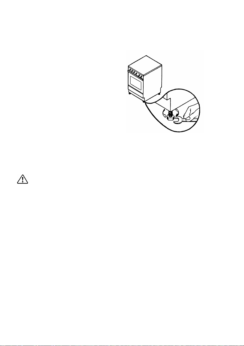
Replace the nozzles of the hob
burners
Hob burners
• Remove the pan supports;
• Remove the caps and the burner
crowns;
• Using a No 7 socket spanner
unscrew the nozzles and replace
them with those required for the
type of gas in use (see burners
characteristics table above).
Reassemble the parts following the
same procedure in reverse.
These burners do not need any
primary air regulation.
Gas Type
Natural Gas
U-LPG
Natural Gas
U-LPG
Natural Gas
U-LPG
Pressure
(kPa)
1,00
2,60
1,00
2,60
1,00
2,60
Nozzle
diameter
(mm)
1,39
0,90
1,11
0,71
0,89
0,55
14
Page 15

Adjustment of minimum level for
the hob burners
The burner is correctly adjusted
when the flame is stable silent and
goes out without any noise.
When changing the type of gas
check that the minimum level is
correct. The air admission is correct
when the flame is about 4 mm in
length.
The top burners do not need
adjustment of primary air.
Check that, turning the knob quickly
from the maximum position to the
minimum one, the flame does not go
out.
Hob burners
To adjust the minimum level:
• Light the burner
• Turn the knob to the position of
the minimum flame;
• Remove the knob;
• Unscrew or screw the by-pass
screw until a regular small flame
is reached.
• For U-LPG screw completely the
by-pass screw.
Reassemble the parts following the
same procedure in reverse.
Check that, when turning the knob
quickly from the maximum position to
the minimum one, the flame does not
go out.
no air
correct
adjustment
excess of
air
15
Page 16

Electrical connections
Any electrical work required
to install this cooker and the
supply cable should be carried out
by a qualified licensed electrician,
in accordance with the current
regulations.
This cooker must be earthed.
The manufacturer disclaims
any responsibility should these
safety instructions not be carried
out.
Before any maintenance or
cleaning can be carried out, you
must DISCONNECT the cooker
from the electricity supply.
This cooker is designed to be
connected to a 230-240V AC, 50Hz
electrical supply.
To connect to the electricity supply,
use cable type H05 RR-F.
Before connection, make sure the
electricity supply voltage is the same
as that indicated on the rating plate.
The cooker is supplied with supply
cable incorporating a 10A plug.
Connect the plug to an appropriate
10A socket. Any electrical work for
example to install a 10A socket must
be completed by a licensed
electrician.
If hard wiring to the mains is
required, an omnipolar interrupter
with a minimum opening of 3 mm
between contacts dimensioned to
the voltage and corresponding to
the regulations in force, should be
interposed between the appliance
and the supply.
The interrupter must not interrupt
the yellow-green earth cable.
After installation and connecting,
the cable must be placed so that it
cannot at any point reach a
temperature of more than 50°C
above the ambient temperature.
NO
supply
cable
After connection try out the heating
elements allowing them to function
for approximately 3 minutes.
If the supply cable is
damaged, the manufa cturer or its
service agent or a similarly
qualified person must replace it
in order to avoid a hazard.
16
Page 17

17
Page 18

Instructions for the User
Use and care
Control panel
TEMPERATURE FUNCTION
1
2 4 6
3
1. Back left burner control knob
2. Front left burner control knob
3. Front right burner control knob
4. Back right burner control knob
Hob
1. Back left burner (auxiliary)
2. Front left burner (rapid)
1
2
5
7
9
8
5. Ignition switch
6. Oven thermostat
7. Oven thermostat pilot light
8. Function pilot light
9. Oven function control knob (selector)
4
3
3. Front right burner (semi-rapid)
4. Back right burner (semi-rapid)
18
Page 19

Use of Appliance
Before the First Use of the Oven
Before the first use ensure
that the room is well ventilated:
V.M.C. (Mechanic ventilation) or
opened window.
Remove all packaging, both
inside and outside the oven,
before using the oven.
Before first use, the oven should be
heated without food. During this
time, an unpleasant odour may be
emitted. This is quite normal.
1. Remove the oven accessories.
2. Remove any adhesive labels or
protective films, if there are any.
3. Heat the oven the corresponding
knob on position “250” for about
45 min.
This procedure should be repeated
with the grill func tion for approximately
5-10 minutes.
Clean the accessories with a soft
detergent. Rinse and dry carefully.
About condensation and steam
When food is heated it produces
steam in the same way as a boiling
kettle. The oven vents allow some of
this steam to escape. However,
always stand back from the oven
when opening the oven door to
allow any build up of steam or heat to
release.
If the steam comes into contact with
a cool surface on the outside of the
oven, e.g. a trim, it will condense and
produce water droplets. This is quite
normal and is not a fault with the oven.
To prevent discolouration, regularly
wipe away condensation and also
spillage from surfaces.
Cookware
Use any ovenproof cookware,
which will withstand temperatures
°
of 250
door becomes hot. Take care
that children do not play near it.
C.
Oven dishes, etc. should not be
placed directly on the oven base.
During cooking the oven
19
Page 20

Electric Oven
Oven Function Control Knob
Oven switched off
Bake
Grill The grill cannot be used at
Base
Heat
Fan
Bake
Defrost
Conventional cooking –
The heat comes from both
the top and bottom element,
ensuring even heating inside
the oven
the same time as the oven.
The oven door must be
closed when grilling.
Bottom heating element –
The heat comes from the
bottom of the oven only.
Fan cooking – Heat is
transmitted to food by means
of pre-heated air throughout
a fan located on the back
wall of the oven.
This setting is intended to
assist in thawing of frozen
foods.
Thermostat Control Knob
By turning the oven control knob
clockwise, you select the cooking
temperature.
The temperatures shown here are on
the actual control knob.
Temperature selection starts at 50°C
and will reach approximately 250°C at
the centre of the oven.
The thermostat controlling the
temperature is variable so it is possible
to select temperatures between those
marked.
The maximum setting is particularly
suitable for grilling.
20
Page 21

Things to note
Once the oven temperature has
been selected, the oven thermostat
pilot light will come on and remain
on until the oven has reached the
correct setting; after that, it will go on
and off with the thermostat, showing
how the temperature is being
maintained.
Caution
Do not place pans, dripping pans,
baking trays or aluminium foil directly
on the base of the oven. This could
cause a heat build-up, which could
affect the performance of the oven and
damage the oven enamel.
Using the Conventional Oven
When using this setting, heat comes
from both the top and bottom
elements. This allows you to cook
on a single level and is particularly
suitable for dishes, which require
extra base browning such as
quiches and flans.
Gratins, lasagnas and hotpots,
which require extra top browning
also cook well in the conventional
oven.
This form of cooking gives you the
opportunity to cook without the fan in
operation.
How to use the Conventional
Oven
- Turn the oven function control
knob to the cooking function
«Bake».
- Turn the thermostat control knob
to the selected temperature.
Bottom oven element only
This function is particularly useful
when blind- baking pastr y or co oking
pizza. It may also be used to finish
off quiches or flans to ensure the
base pastry is cooked through.
Hints and Tips
There should always be at least
2.5cm between the top of the food
and the element. This gives the best
cooking results and allows room for
rise in yeast mixtures, Yorkshire
puddings, etc. When cooking cakes,
pastry, scones, bread, etc., place
the tins or baking trays centrally
below element.
Ensure that food is placed centrally
on the shelf and there is sufficient
room around the baking tray/dish to
allow for maximum circulation.
Stand dishes on suitably sized
baking trays to prevent spillage onto
the oven base and to help reduce
cleaning.
Enamelware, dark, or heavy utensils
increase base browning. Shiny
aluminium or polished steel trays
reflect the heat away and give less
base browning.
DO NOT place dishes directly onto
the oven base as it becomes very
hot and damage may occur.
DO NOT uses the grill pan or meat
tin as a baking tray as this will
increase base browning of the food.
For economy leave the door open
for the shortest possible time,
particularly when placing food into a
preheated oven.
21
Page 22

Grilling
When grilling, the accessible
parts of the appliance are hot and
the appliance should not be left
unattended. Take care that children
do not play near it.
The grill pan will become hot
during use, always use oven gloves
when removing or replacing a hot
grill pan.
All grilling must be carried out
with the oven door closed.
To switch on the grill, turn the
oven function control knob to «Grill»,
and then turn the thermostat knob to
the maximum temperature.
Most foods should be placed on the
grid in the grill pan to allow maximum
circulation of air to lift the food out of
the fats and juices. Food such as
fish, liver and kidneys may be placed
directly on the grill pan, if preferred.
Adjust the grid and grill pan runner
position to allow for different thickness
of food.
Food should be thoroughly dried
before grilling to minimise splashing.
Brush lean meats and fish lightly with
a little oil or melted butter to keep
them moist during cooking.
Accompaniments such as tomatoes
and mushrooms may be placed
underneath the grid when grilling meats.
When toasting bread, we suggest
that the top runner position is used
with the grid in its 'high' position.
Preheat the grill on a full setting for
a few minutes before sealing steaks
or toasting. Adjust the heat setting
and the shelf as necessary, during
cooking.
The food should be turned over
during cooking, as required.
NOTE: For safety in use, the
thermostat controls the grill
element. During cooking, the grill
cycles on and off to prevent
overheating.
Cooking time depends on the
thickness of the meat and not on its
weight.
Using the Fan Oven
The air inside the oven is heated by
the top and bottom elements. The
fan circulates hot air to maintain an
even temperature inside the oven.
The advantages of cooking with
this function are:
How to use the Fan Oven
- Turn the oven function control
knob to the cooking function «Fan
Bake».
- Turn the thermostat control knob
to the selected temperature.
22
Page 23

Faster Preheating
As the fan oven quickly reaches
temperature, it is not usually
necessary to preheat the oven
although you may find that you need
to allow an extra 5-7 minutes on
cooking times. For recipes, which
require higher temperatures, best
results are achieved if the oven is
preheated first, e.g. bread, pastries,
scones, souffles, etc.
Lower Temperatures
Fan oven cooking generally requires
lower temperatures than conventional
cooking.
Remember to reduce temperatures
by about 20- 25°C for your own recipes,
which use conventional cooking.
Even Heating for Baking
The fan oven has uniform heating on
all runner positions. This means that
batches of the same food can be
cooked in the oven at the same time.
However, the top shelf may brown
slightly quicker that the lower one.
This is quite usual. There is no
mixing of flavours between dishes.
Defrosting
The defrosting function allows you to
defrost frozen foods. The oven fan
operates without heat and circulates
the air, at room temperature, inside
the oven. This increases the rate at
which defrosting takes place.
This function is particularly suitable
for delicate food which could be
damaged by heat, e.g. cream filled
gateaux, iced cakes, pastries, bread
and other yeast products.
How to use Defrosting
- Turn the oven function control
knob to the required cooking
function « Defrost ».
It is not possible to adjust the
temperature.
Hints and Tips
• Cover food with a lid, aluminium
foil or plastic film to prevent
drying out during defrosting.
• Place the food to be defrosted
in a single layer where possible
and turn it over half way through
the defrosting process.
• DO NOT leave food at room
temperature once it is defrosted.
Cook raw food immediately or
store cooked food in the fridge.
• Take care to follow the basic
rules for hygiene when handling
fresh, frozen, raw and cooked
foods.
Main pilot light
This light will illuminate when the
oven function control knob is set
and lights during the oven
functioning.
Oven light
The oven light will come on when
the oven function control knob is
set and lights during the oven
functioning.
23
Page 24

Oven Cooking Chart
The data in the chart bellow are informative. Only experience will enable you to
determine the correct setting for your personal requirements.
Type of Cake
or Pastry
Pastry stripes
Small cakes
Christmas cake
Crumble cake
Meringue
Yeast buns
Flat cake
Fatless sponge
cake
Cheese cake
Swiss roll
Petit Choux
Yeast cake with
apples
Shelf
position
from the
bottom
Pre-
heating
Min
3 10-13 160-180
1+2+3 7-10 ---- 140-160
2 10-13 170-190
1+3 10-12 ---- 165-175
2 15-20
3 ---- ---- 150-160 45+10
3 15-20 190-200
3 ---- ---- 165-175 25-35
2 ---- 115-125
1+2+3 ---- ---- 115-125 45-55
2 10-15 215-235
2 10-13 ---- 180-200
2 10-13 170-190
2+3+4 7-10 ---- 150-170
2 10-13 170-180
2 7-10 ---- 150-160
2 ---- 170-190
2 ---- ---- 150-170 50-70
1 10-13 170-190
1 10-13 ---- 160-180
2 10-15 190-200
2 10-13 ---- 190-200
3 ---- 180-200
3 ---- ---- 160-180 45-50
Bake
Temp.
°C
*
250
160-180
Fan bake
Temp.
°C
Cooking
time
Min
---- 20-25
40-45
---- 25-35
25-30
---- 45+10**
**
---- 25-35
---- 40-50
---- 10-20
10-20
---- 25-30
40-45
---- 20-25
30-35
---- 50-70
---- 15-20
10-20
---- 10-20
10-20
---- 45-50
24
Page 25

Type of Cake
or Pastry
position
from the
bottom
Shelf
Apple pie
1
2+2
Drip pan cake
2
2
Peasant bread
Quiche Lorraine
1
1
2
Pizza
2
1+3
*
- Preheating temperature
**
-Maintaining time in the oven after switching off of the oven function control knob
Pre-
heating
min
10-13
----
----
---15-20
15-20
10-15
----
----
Bake
Temp.
°C
175-185
Fan bake
Cooking
Temp.
°C
---- 55-60
---- 165-175 50-55
170-180
---- 50-55
---- 145-155 50-55
250*
195-205
220-240
---- 200-220
210-230
---- 40-60
---- 20-40
---- 25-30
---- 190-200 25-30
Roasting chart
Shelf
FOOD
position
from the
bottom
Bake
°C
Chicken entire 2 195-205
Half chicken 3 195-205
Time
Min.
60-70 2 170-190 45-50
30+30 - - -
Shelf
position
from the
bottom
Fan
bake
°C
time
min
20-40
Time
Min.
Pork roast cutlet 3 195-205 100-105 2 160-180 45-50
Grilling chart
Type of Cake or
Pastry
position
from the
bottom
Toast 3 10 230
Hochsteaks 2 10 200 20+20
Half chicken 2 - 230 35+35
Pork roast cutlet 2 - 230 30+30
Shelf
Pre-
heating
Min.
Grill
°C
Time
Min.
4-6
25
Page 26

Using the Hob
The symbol on the control panel shows
which burner is operated by the knob.
(See control panel).
Off
Maximum level
HI
Minimum level
LO
Use the maximum level for boiling and
the minimum for simmering.
Always choose positions between the
minimum and maximum, never
between maximum and off.
Ignition of the burners
• Push the knob and turn it left to the
maximum level “HI“.
• At the same time, push the
electronic ignition knob (see fig).
Keep it pushed until the gas ignites
(1 spark / second).
• Release the knob and check that
the burner has ignited.
• Upon ignition, adjust the flame as
required.
OR
Power Cut
• Push the corresponding knob in
completely and turn it left to the
maximum level “HI“ and ignite with
a match.
• Release the knob and check that
the burner has ignited.
• Upon ignition, adjust the flame as
required.
If for any reason the flame should
extinguish turn off the relevant
control knob, leave for at least one
minute and then re-ignite.
26
Page 27

If after a few attempts the burner does
not ignite, check that the burner ring and
its cap are correctly positioned.
Turning off the burners
Turn the control knob clockwise to mark «
».
Do not put anything on the hob
that is liable to melt.
Selecting the Correct burner
Above every knob there is a symbol for
the corresponding burner.
For good cooking results, always choose
pans, which correctly fit to the diameter
of the burner used.
Choose thick, flat bottom pots.
Do not place anything, eg. flame
tamer, asbestos mat, between pan
and pan support as serious damage to
the appliance may result.
Do not remove the pan support
and enclose the burner with a wok
stand as this will concentrate and
deflect heat onto the hotplate.
Do not use large pots or heavy
weights which can bend the pan
support or deflect flame onto the
hotplate.
Locate pan centrally over the
burner so that it is stable and does
not overhang the appliance.
27
Page 28

We recommend the flame be lowered
as soon as the liquid starts boiling.
For a correct ignition always keep the
burner ring and the spark plugs clean.
The following diameter pans can be used:
Burner
Diameter (mm)
min. max.
Rapid 220 280
Semi-Rapid 160 240
Auxiliary 120 180
Accessories delivered with
the appliance
The following accessories are supplied
with your appliance.
• Shelf for placing dishes on (2 pieces)
The dish should be put in the middle of
the shelf to balance the weight.
• A ro asting tray w ith roasting grid on
it. It is used to collect juice when
cooking in it, place it on the shelf 2.
If you do not use the roasting tray,
remove it from the oven.
In addition to the accessories supplied
we recommend you only use heatproof
dishes/pans (according to the
manufacturer’s instructions).
28
Page 29

Removable drawer
The removable drawer is located
underneath the oven cavity.
During cooking the drawer
may become hot if the oven is in
use for a long period of time.
Flammable materials such as oven
gloves, tea towels, plastic aprons,
aerosols etc. should not be stored
in the drawer.
Oven accessories such as baking
sheets, will also become hot,
therefore care should be taken when
removing these items from the
drawer whilst the oven is in use or
still hot.
To open
• Grasp the drawer from underneath
and pull it out as shown.
• To remove the drawer, pull it out
to the stop, then lift it up slowly
and pull it out completely.
To replace the drawer follow the
same procedure in reverse.
29
Page 30

Maintenance and Cleaning
The oven should be kept
clean at all times. A build-up of
fats or other foodstuffs could
result in a fire.
Before cleaning, ensure all
control knobs are in the OFF
position, and the appliance has
cooled completely.
Before any maintenance or
• Chemical oven pads or aerosols
• Rust removers
• Bath/Sink stain removers
Clean the outer and inner door glass
using warm soapy water. Should
the inner door glass become heavily
soiled it is recommended that a
cleaning product such as Hob Brite,
or Bar keepers Friend is used.
cleaning can be carried out, you
must DISCONNECT the cooker
from the electricity supply.
=
Cleaning materials
Before using any cleaning materials
on your oven, check that they are
suitable and that the manufacturer
recommends their use.
DO NOT clean the oven
door while the glass panels are
warm. If this precaution is not
observed the glass panel may
shatter.
If the door glass panel becomes
chipped or has deep scratches, the
glass will be weakened and must
be replaced to prevent the
Cleaners that contain bleach
should NOT be used as they may
dull the surface finishes. A steam
cleaner is not to be used. Harsh
abrasives should also be avoided.
External cleaning
Regularly wipe over the control
panel, oven door and door seal using
a soft cloth well wrung out in warm
possibility of the panel shattering.
Contact your local Service Centre
who will be pleased to advise
further.
Models in stainless steel
The stainless steel parts may
become straw colored with use. Use
a proprietary stainless steel cleaner
to remove this straw discoloration.
water to which a little washing up
liquid has been added.
To prevent damaging or
weakening the door glass panels
avoid the use of the following:
• Household detergent and bleaches
• Impregnated pads unsuitable for
Oven Cavity
Wipe the oven over with a soft cloth
soaked in warm soapy water after
each use. From time to time it will
be necessary to do a more
thorough cleaning, using a
proprietary oven cleaner.
non-stick saucepans
• Brillo/Ajax pads or steel wool pads
30
Page 31

Cleaning the Oven Door
Removing oven door from its hinges
To make it easier to clean the oven, the
oven door can be removed.
Open the oven door into the horizontal
position. Then lift up the clips on the two
door hinges as far as they will go (a).
Slowly close the door again as far as the
stop and lift the door until the hinges
come out (b).
Replacing the oven door on its
hinges
When putting the door back on its
hinges, reverse the procedure for
removing the door from its hinges.
Re-insert the door’s hinges into the slots
(c). When you do this, make sure the
hinges engage properly and evenly.
Then slowly lower the door downwards.
When you do this, make sure the
corners of the door do not touch the
bottom of the frame (if this happens, lift
the door up again and realign the
hinges).
Finally fold the clips back down towards
the oven (d). So that the door closes
properly, press down on the clips with
something (e.g. a screwdriver) (e).
Slowly check the correct operation of the
door.
Important: Never leave the door hinge
levers standing up. Otherwise the spring
action can lead to injury.
31
Page 32

Oven Shelves and Shelf
support
1. Unscrew the fixing screws (A) then
take the side racks from the oven
out. Wash the racks and shelves
by hand or in a dishwasher. If very
soiled, soak them first, before
cleaning with a steel wool pad.
2. Reassemble the parts following the
same procedure in reverse.
The baking trays and oven dish should
be wiped clean with paper towels, or
washed by hand when necessary. Any
burnt-on food can be removed using a
suitable spatula.
Hob
After every use wipe with a soft cloth
well wrung out in warm water to which
a little washing up liquid has been
added, avoiding any leakage through
the holes of the hob. Rinse and dry
with a soft cloth.
32
Page 33

To remove more stubborn stains, wet
and leave to dissolve, do not scratch
and avoid the use of abrasive or
caustic products that could damage
the enamel.
Burners
The burner caps and crowns can be
removed for cleaning. Wash the
burners’ caps and crowns using hot
soapy water, and remove marks with a
mild paste cleaner. A well-moistened
soap impregnated steel wool pad can be
used with caution, if the marks are
particularly difficult to remove.
After cleaning, be sure to wipe dry with
a soft cloth.
Oven Bulb Replacement
Burner
cap
Burner
ring
Burner
body
Ensure that the appliance is
switched off and disconnected from
the electricity supply before replacing
the bulb to avoid possibility of an
electric shock.
If the oven bulb needs replacing, it mus t
comply with the following specifications:
Wattage: 25W
Voltage: 240V (50Hz)
Temperatures: 300ºC
Thread Type: E14
To replace the faulty bulb
1. Turn the glass cover anticlockwise
and remove.
2. Remove the faulty bulb and replace
with a new one.
3. Refit the glass cover.
4. Reconnect the appliance to the
electricity supply.
33
Page 34

Something not working
If the appliance is not working correctly, please carry out the following checks,
before contacting your local Authorized Service Centre.
IMPORTANT: If you call out an engineer to a fault listed below, or to repair
a fault caused by incorrect use or installation, a charge will be made even
if the appliance is under guarantee.
Symptoms Solutions
The flow of gas seems abnormal Check that:
• The flame spreader holes are not obstructed
• The pressure regulator is working
• The bottle valve or gas mains valve is
completely open
No burner ignition Check that:
• Gas supply is complet ely open
• The position of gas pipe is correct
• The burner is not wet
• The burner cap and ring burner have been
replaced correctly after cleaning
• The power is on
The gas ring burns unevenly Check that:
The main jet is not blocked and the ring
•
burner is clean of food particles
• The burner cap and ring burner have been
replaced correctly after cleaning
The oven does not come on Check:
• Check if a cooking function/temperature has
been selected correctly
• The power socket switch or the switch from
the mains supply to the cooker is ON.
It takes too long to finish the
dishes, or they are cooked too
fast
The oven lamp does not work
Check:
• The temperature may need adjusting
Check:
• The power is on
• The lamp has not burnt out. To replace it
follow the instructions given in the relevant
paragraph.
34
Page 35

If after these checks, the appliance still does not operate correctly, contact your
local Authorized Service Centre. When you contact the Authorized Service
Centre you will need to give the following details:
1. Your name, address and postcode.
2. Your telephone number
3. Clear and concise details of the fault
4. The model and serial number of the appliance (found on the rating plate*)
5. The purchase date
* The rating plate can be found on the lower left hand corner of the front frame
of the cavity (see fig.).
35
Page 36

Warranty
FOR SALES IN AUSTRALIA AND NEW ZEALAND
APPLIANCE:
This document sets out the terms and
conditions of product warranties for
Electrolux branded appliances. It is an
important document. Please keep it with
your proof of purchase documents in a
safe place for future reference should you
require service for your Electrolux appliance.
General Terms and Conditions
1. In this warranty
(a) 'Electrolux' means Electrolux Home Products
Pty Ltd ABN 51 004 762 341 in respect of
Appliances purchased in Australia and
Electrolux (NZ) Limited in respect of
Appliances purchased in New Zealand;
(b) 'Appliance' means any Electrolux product
purchased by you accompanied by this
document;
(c) 'Warranty Period' means
(i) where you use the Appliance for
(i) where you use the Appliance for
(d) 'you' means the purchaser of the
Appliance not having purchased the
appliance for re-sale, and 'your' has a
corresponding meaning.
2. This warranty only applies to Appliances
purchased and used in Australia or New
Zealand and is in addition to (and does not
exclude, restrict, or modify in any way) any
non-excludable statutory warranties in
Australia or New Zealand.
3. Electrolux warrants that, when dispatched
from an Electrolux warehouse, the
Appliance is free from defects in materials
and workmanship for the Warranty Period.
4. During the Warranty Period Electrolux or its
Authorised Service Centre will, at no extra
charge if your appliance is readily accessible
[FREESTANDING COOKER]
personal, domestic or household
purposes in Australia the period of 24
months and in New Zealand the
period of 24 months;
commercial purposes, in Australia the
period of 3 months and in New
Zealand the period of 3 months, (if the
period stated is 0 months you are not
covered by this product warranty)
following the date of original purchase
of the Appliance;
without special equipment, and subject to
these terms and conditions, repair or
replace any parts which it considers to be
defective. You agree that any replaced
Appliances or parts become the property
of Electrolux. This warranty does not
apply to light globes, batteries, filters or
similar perishable parts.
5. Parts and Appliances not supplied by
Electrolux are not covered by this warranty.
6. Where you are within an Electrolux
service area, this warranty covers the cost
of transport of the Appliance to and from
Authorised Service Centres of Electrolux
and travelling costs for representatives of
the Authorised Service Centre to and from
your home or business. If you are outside
an Electrolux service area, you will bear
these costs. For information about
whether you are within an Electrolux
service area, please phone 13 13 49 in
Australia, or 0800 10 66 10 in New Zealand.
7. Proof of purchase is required before you
can make a claim under this warranty.
8. You may not make a claim under this
warranty unless the defect claimed is due
to faulty or defective parts or workmanship.
Electrolux is not liable in the following
situations (which are not exhaustive):
a) The Appliance is damaged by:
(i) accident
(ii) misuse or abuse, including failure to
properly maintain or service
(iii) normal wear and tear
(iv) power surges, electrical storm damage
or incorrect power supply
(v) incomplete or improper installation
(vi) incorrect, improper or inappropriate
operation
(vii) insect or vermin infestation.
b) The Appliance is modified without authority
from Electrolux in writing.
c) The Appliance's serial number or warranty
seal has been removed or defaced.
d) The Appliance was serviced or repaired
by anyone other than Electrolux or its
Authorised Service Centres.
36
Page 37

9. This warranty, the contract to which it
relates and the relationship between you
and Electrolux are governed by the law
applicable in the Australian State where
the Appliance was purchased or the law
applicable in New Zealand if the
Appliance was purchased in New
Zealand. Where the Appliance was
purchased in New Zealand for business
purposes the Consumer Guarantee Act
does not apply.
Limitation of Liability
10. To the extent permitted by law:
a) Electrolux excludes all warranties other than
as contained in this document;
b) Electrolux shall not be liable for any loss or
damage whether direct or indirect or
consequential arising from your purchase,
use or non-use of the Appliance.
c) Electrolux shall not be liable for any loss or
damage whether direct or indirect or
consequential arising from your purchase,
use or non-use of the Appliance.
11. Provisions of the Trade Practices Act and
State consumer legislation in Australia, and
the Consumer Guarantees Act, the Sale of
Goods Act and the Fair Trading Act in New
Zealand, imply warranties or conditions, or
To the extent permitted by law, the liability
of Electrolux (if any) arising out of or in
relation to the Appliance or any services
supplied by Electrolux shall be limited
(where it is fair and reasonable to do so),:
a) in the case of Appliances, at its option, to
the replacement or repair of the Appliances
or the supply of equivalent products or the
payment of the cost of replacing the
Appliances or having the Appliances
repaired or of acquiring equivalent
Appliances. Upon being replaced, parts
and Appliances become the property of
Electrolux; or
b) in the case of services, at its option, to the
supply of the services again or the
payment of the cost of having the services
re-supplied;
and in the case of Appliances or services
supplied in New Zealand, loss or damage
whether direct or indirect or consequential
that is reasonably foreseeable.
Privacy
You acknowledge that in the event that you
make a warranty claim it will be necessary
for Electrolux and its Authorised Service
Centres to exchange information in
relation to you to enable Electrolux to
meet its obligations under this warranty.
impose obligations, upon Electrolux which
cannot be excluded, restricted or modified.
Important Notice
Before Calling a Service Technician please check carefully the operating instructions, service
FOR SERVICE
OR TO FIND THE
ADDRESS OF YOUR
NEAREST STATE
SERVICE CENTRE IN
AUSTRALIA
Please call 13 13 49
For the cost of a local call
(Australia only)
FOR SERVICE
OR TO FIND THE
ADDRESS OF YOUR
NEAREST
AUTHORISED
SERVICE CENTRE IN
NEW ZEALAND
Free call 0800 10 66 10
(New Zealand only)
booklet and the warranty terms and conditions.
SERVICE AUSTRALIA
ELECTROLUX HOME PRODUCTS
FOR SPARE PARTS
OR TO FIND THE
ADDRESS OF YOUR
NEAREST STATE SPARE
PARTS CENTRE IN
AUSTRALIA
Please call 13 13 50
For the cost of a local call
(Australia only)
NEW ZEALAND SPARE PARTS CENTRES
AUCKLAND Prime Distributors Ltd. 8 Highbrook Drive, East Tamaki……….…(09) 273 3580
CHRISTCHURCH Prime Distributors Ltd. Unit 1, 127 Montreal Street………..(03) 377 1009
R. Redpath Ltd. 55 Ferry Road…...………………….………(03) 379 0446
DUNEDIN Appliance Parts Company, 590 Hillside Road……………………...…(03) 455 5443
ELECTROLUX HOME PRODUCTS
37
Page 38

38
Page 39

39
Page 40

342 726 369 –00-18.01.2007
40
 Loading...