

AEG 75857G-M User Manual [pt]
75857 G-M
EN
RU
PT
instruction booklet
Pуководство по эксплуатации
Instruções de utilização
gas hob
Варочные панели
Plano de cozedura

2
Thank you for choosing one of our high-quality products.
To ensure optimal and regular performance of your appliance please read thisinstruction
manual carefully. It will enable you to navigate all processes perfectlyand most efficiently.
To refer to this manual any time you need to, we recommendyou to keep it in a safe place.
And please pass it to any future owner of the appliance.
We wish you much joy with your new appliance.
Contents
For the User For the Installer
3
Important Safety Information 4
Operation 6
Using the hob correctly 7
Cleaning and Maintenance 8
European Guarantee 19
Technical data 10
Installation 12
Adaptation to different types of gas 14
Electrical Connection 15
Building In 16
Possibilities for insertion 18
Guide to Use the instructions
The following symbols will be found in the text to guide you throughout the Instructions:
Safety Instructions
Step by step instructions for an operation
)
Hints and Tips
Environmental information
This appliance complies with the following E.E.C. Directives:
••
• 2006/95 (Low Voltage Directive);
••
••
• 2004/108 (Electromagnetical Compatibility Directive);
••
••
• 90/396
••
(General Directives) and subsequent modifications.
MANUFACTURER:MANUFACTURER:
MANUFACTURER:
MANUFACTURER:MANUFACTURER:
ELECTROLUX ITALIA S.P.A.
C.so Lino Zanussi, 30
33080 Porcia (PN) - Italy
It is very important that this instruction book should be kept safely for future consultation. If
the appliance should be sold or given to another person, please ensure that the booklet goes
together with it, so that the new owner can know of the functions of the machine and also
be aware of the warnings.
These instructions are only for the countries stated by the symbol printed on the front cover
of this instruction book.
4
English
Important safety information
This warnings has been given for the safety of you and others. We therefore ask you to
carefully read the procedures of installing and using this cooker.
Installation
z The work of installation must be carried out
by competent and qualified installers
according to the regulations in force.
• Any modifications to the domestic
electrical mains which may be necessary for
the installation of the appliance should be
carried out only by competent personnel.
During Operation
• This appliance has been designed for non
professional purpose in private houses only.
It is meant to cook edible foodstuff only and
must not be used for any other purposes.
• It is dangerous to alter the specification in
any way.
• For hygiene and safety reasons, this
appliance should be kept clean at all times.
A build-up of fats or other foodstuff could
result in a fire.
• Under no circumstances should you
attempt to repair the appliance yourself.
Repairs carried out by unexperienced
persons may cause injury or serious
malfunctioning. Refer to your local Service
Centre. Always insist on genuine spare
parts.
• Ensure that all control knobs are in the OFF
position when not in use.
• Should you connect any electrical tool to a
plug near this cooking appliance, ensure
that electric cables are not in contact with
it and keep them far enough from the
heated parts of this appliance.
• If the appliance is out of order, disconnect it
from the electric supply.
People Safety
• This appliance has been designed to be
operated by adults and children under
supervision. Young children must not be
allowed to tamper with the controls or play
near or with the oven.
• This appliance is not intended for use by
children or other persons whose physical,
sensory or mental capabilities or lack of
experience and knowledge prevents them
from using the appliance safely without
supervision or instruction by a responsible
person to ensure that they can use the
appliance safely.
• Accessible parts of this appliance may
become hot when it is in use. Children
should be kept away until it has cooled.
About Installation, Cleaning and
Manteinance
z It is mandatory that all operations required
for the installation are carried out by a
qualified or competent person, in
accordance with existing rules and
regulations.
• Disconnect the appliance from the
electrical supply, before carrying out any
cleaning or manteinance work.
• Ensure a good ventilation around the
appliance. A poor air supply could cause
lack of oxygen.
• Ensure that the gas supply complies with
the gas type stated on the identification
label, placed near the gas supply pipe.
5
• This appliance is not connected to a
combustion products evacuation device. It
must be installed and connected in
accordance with current installation
regulations. Particular attention shall be
given to the relevant requirements
regarding ventilation.
• The use of a gas cooking appliance results
in the production of heat and moisture in
the room in which it is installed. Ensure
that the kitchen is well ventilated: keep
natural ventilation holes open or install a
mechanical ventilation device
(mechanical extractor hood).
• Prolonged intensive use of the appliance
may call for additional ventilation, for
example opening of a window, or more
effective ventilation, for example
increasing the level of mechanical
ventilation where present.
• Once you removed all packaging from the
appliance, ensure that it is not damaged
and the electric cable is in perfect
conditions. Otherwise, contact your dealer
before proceeding with the installation.
• The manufacturer disclaims any
responsability should all the safety
measures not be carried out.
Environmental Information
z After installation, please dispose of the
packaging with due regard to safety and
the environment.
• When disposing of an old appliance, make
it unusable, by cutting off the cable.
The symbol on the product or
on its packaging indicates that this product
may not be treated as household waste. Instead
it shall be handed over to the applicable
collection point for the recycling of electrical
and electronic equipment. By ensuring this
product is disposed of correctly, you will help
prevent potential negative consequences for
the environment and human health, which
could otherwise be caused by inappropriate
waste handling of this product. For more
detailed information about recycling of this
product, please contact your local city office,
Service
• Under no circumstances should you
attempt to repair the appliance yourself.
Repairs carried out by unexperienced
persons may cause injury or serious
malfunctioning. Refer to your local Service
Centre. Always insist on genuine spare
parts.
6
Operation
Hob burner control knobs
The symbols on the knobs mean:
z = no gas supply
= maximum gas supply
= minimum gas supply
For easier lighting, proceed before
putting a pan on the pan support.
Lighting the burners
)
To light a burner, turn the relevant knob
anticlockwise to maximum position ( )
and push down the knob to ignite.
After lighting the flame, keep the knob
pushed down for about 5 seconds. This will
allow the "thermocouple" to be heated and
the safety device to be switched off,
otherwise the gas supply would be
interrupted. Then, check the flame is regular
and adjust it as required.
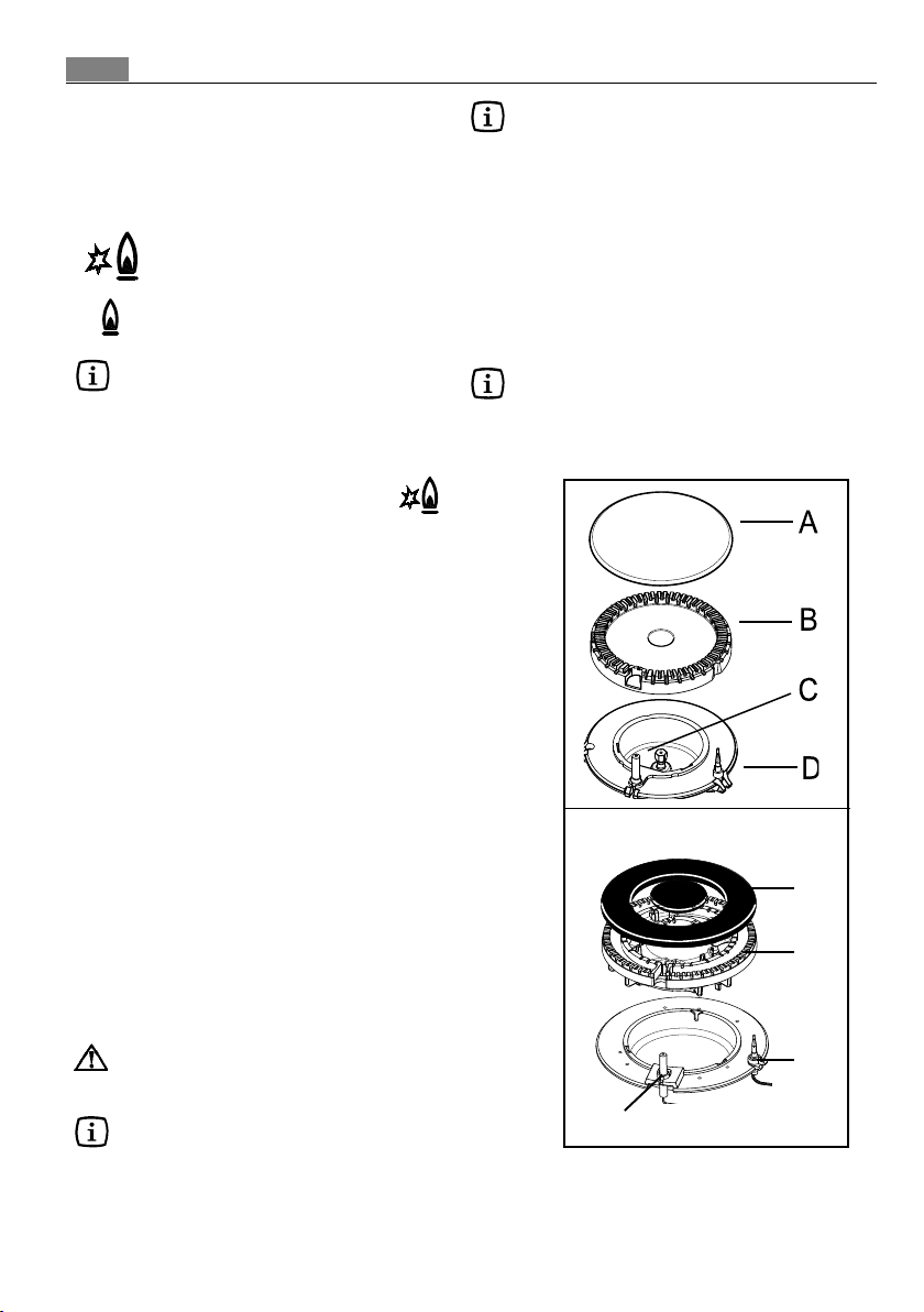
If you cannot light the flame even after
several attempts, check the "cap" and
“crown” are in the correct position(Fig.1).
In the absence of electricity, ignition can
occur without the electrical device; in this
case approach the burner with a flame, push
the relevant knob down and turn it anticlockwise until it reaches the "maximum"
position.
To switch off burners
)
To put the flame out, turn the knob to the
symbol (z).
Take care when frying food in hot oil
or fat, as the overheated splashes
could easily ignite.
When switching on the mains, after
installation or a power cut, it is quite
normal for the spark generator to be
activated automatically.
Do not keep the control knob pressed for
more than 15 seconds.
If the burner does not light even after 15
seconds, release the control knob, turn it
the "off" position and wait for at least
one minute before trying to light the
burner again.
If the burner accidentally goes out, turn
the control knob to the "off" position and
wait for at least 1 minute before trying
to light the burner again.
Each control knob is equipped with a
pilot light which gradually lights up
according to the heat level that you
select with the control knob.
Triple Crown burner
A
B
D
C
A - Burner cap
B - Burner crown
C - Ignition candle
D - Thermocouple
Using the hob correctly
Practical hints
The burners
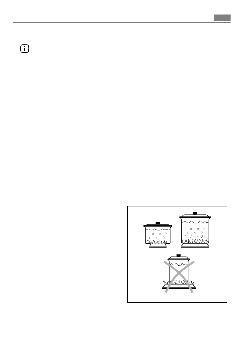
To ensure maximum burner efficiency,
you should only use pots and pans with a flat
bottom fitting the size of the burner used.
Triple Crown Burner
diameter 18-26 cm
Rapid Burner
diameter 18-26 cm
Front Semi-rapid Burner
diameter 12-18 cm
Rear Semi-rapid Burner
diameter 12-22 cm
Auxiliary Burner
diameter 8-18 cm
• For easier lighting, proceed before putting
a pan on the pan support.
• Use only pans or pots with flat bottom.
• Take care when frying food in hot oil or
fat, as the overheated splashes could
easily ignite.
• If you use a saucepan which is smaller than
the recommended size, the flame will
spread beyond the bottom of the vessel,
causing the handle to overheat.
• Prolonged cooking with potstones,
earthenware pans or cast-iron plates is
inadvisable. Also, do not use aluminium
foil to protect the top during use.
• Make sure pots do not protrude over the
edges of the cooktop and that they are
centrally positioned on the rings in order to
obtain lower gas consumption.
• Do not place unstable or deformed pots on
the rings: they could tip over or spill their
contents, causing accidents.
• Pots must not enter the control zone.
• If the control knobs become difficult to
turn, please contact your local Service Force
Centre.
7
• As soon as a liquid starts boiling, turn down
the flame so that it will barely keep the
liquid simmering.

8
Cleaning and Mainteinance
Disconnect the appliance from the
electrical supply, before carrying out
any cleaning or manteinance work.
The hob is best cleaned whilst it is
still warm, as spillage can be
removed more easily than if it is left
to cool.
This appliance cannot be cleaned
with steam or with a steam cleaning
machine.
The burners
z The burner caps and crowns can be
removed for cleaning.
z Wash the burners taps and crowns using
hot soapy water, and remove marks with
a mild paste cleaner. A well moistened
soap impregnated steel wool pad can be
used with caution, if the marks are
particularly difficult to remove.
z After cleaning, be sure to wipe dry with a
soft cloth.
z Frequently wash the "caps" and the
"crowns" with hot soapy water, carefully
taking away any built-up of food.
YES
The pan supports
z The pan supports
proof; they must be washed
z After cleaning, make sure that the pan
supports are correctly positioned.
z To make burners work properly, ensure
that pan supports are placed in a way
that the arms are centred upon the
burner as shown in the picture.
z Pay attention when replacing the pan
supports in order to avoid damaging
the hob top.
Hobs with cast iron pan supports:
after cleaning, place the pan
supports back on their position. In
order to carry out this operation
correctly, place the side pan
supports before the central one.
are notare not
are not dishwasher
are notare not
by handby hand
by hand.
by handby hand
NO

The Hob Top
z Regularly wipe over the hob top using a
soft cloth well wrung out in warm water
to which a little wasing up liquid has
been added. Avoid the use of the
following:
- household detergent and bleaches;
- impregnated pads unsuitable for nonstick saucepans;
- steel wool pads;
- bath/sink stain removers.
z Should the hob top become heavily
soiled, the following products are
recommended:
- For stainless steel hobs use a
proprietary stainless steel cleaner.
- For other hobs use Hob Brite or Bar
Keepers Friend.
z Do not leave acid or alkaline substances
(e.g. vinegar, salt, lemon juice, etc.) on
the cooktop.
The Ignition electrode
The electric ignition is obtained through
a ceramic electrode with a metal electrode
(Fig 1 - C). Keep these components very
clean, to avoid difficult lighting, and check
that the burner crown holes (Fig 1 - B) are
not obstructed.
9
10
Technical data
Burner gas power (natural gas 20 mbar)
Triple crown burner 4,0kW
Rapid burner 3,0 kW
Semi-rapid burner 2,0 kW
Auxiliary burner 1,0 kW
Category II2H3B/P
Gas supply natural gas G20 (2H) 20 mbar
Gas connection G 1/2"
Electric supply230 V ~ 50 Hz
Appliance class 3
Hob dimensions
Width 744 mm
Depth 510 mm
Cut out dimensions
Width 560 mm
Depth 480 mm
By-pass diameters
Burner Ø By-pass in 1/100 mm.
Auxiliary 28
Semi-rapid 32
Rapid 42
Triple crown 56
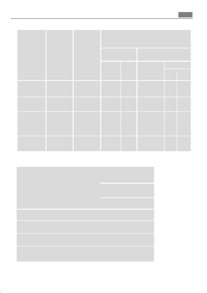
Gas burners
11
NORMAL REDUCED
POWER POWER
BURNER NATURAL GAS LPG
G20 (2H) - 20 mbar
kW kW g/h
inj. m3/h inj.
100/mm 100/mm
Auxiliary
burner 1,0 0,33 70 0,095 50 73 71
Semi-rapid
burner 2,0 0,45 96 0,190 71 145 143
Rapid 3,0
burner (natural gas) 0,75 119 0,286 86 204 200
2,8
(
LPG
)
Triplecrown
burner 4,0 1,2 146 0,381 98 291 286
NORMAL
POWER
(Butane/Propane) 30 mbar
G30 G31
Gas burners G20 13 mbar - only Russia
NORMAL REDUCED
POWER POWER
BURNER
kW kW inj. m3/h
Auxiliary
burner 0,9 0,33 80 0,095
Semi-rapid
burner 1,4 0,45 105 0,148
Rapid
burner 1,9 0,75 120 0,201
Triple crown
burner 3,0 1,2 147 0,318
NORMAL
POWER
NATURAL GAS
G20 - 13 mbar
100/mm
12
Installation
z The following instructions about
installation and maintenance must be
carried out by qualified personnel in
compliance with the regulation in force.
z The appliance must be electrically
disconnected before all interventions. If
any electric supply to the appliance is
required to carry out the work, ensure all
the necessary precautions are followed.
z The side walls of the unit in which the
hob is going to be installed, must not
exceed the height of the working top.
z Avoid installing the appliance in the
proximity of inflammable materials (e.g.
curtains, tea towels etc.).
THE MANUFACTURER WILL NOT ACCEPT
LIABILITY, SHOULD ANY OF THE OTHER
SAFETY INSTRUCTIONS INCORPORATED IN
THIS BOOKLET OR THE REGULATION IN
FORCE BE IGNORED.
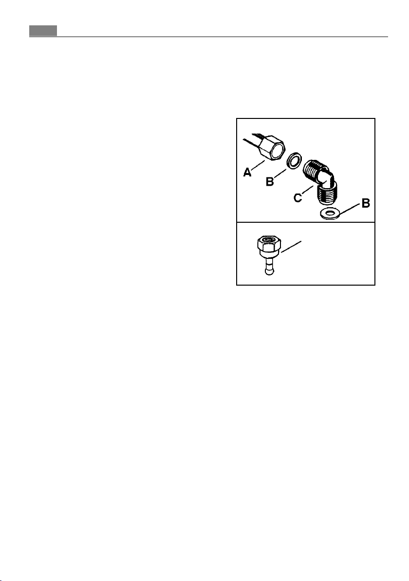
Gas connection
as shown in the picture. Screw the parts
without forcing, adjust the connection in the
required direction and tighten everything.
Natural gas
Liquid gas
D
A) Ramp with ending nut
B) Seal
C) Adjustable connection
D) Rubber pipe holder for liquid
gas
Choose fixed connections or use a flexible
pipe instainless steel in compliance with the
regulation in force. If using flexible metallic
pipes, be careful they do not come in contact
with mobile parts or they are not squeezed.
Use the same attention when the hob is
combinated with an oven.
IMPORTANT - To ensure a correct operation,
a savingof energy and the long life of the
appliance, the voltage pressure of the
appliance must correspond to the
recommended values. The adjustable
connection is fixed to the comprehensive
ramp by means of a threaded nut G 1/2". Interpose the sealing between the components
Connection using flexible nonmetal
pipes
When the connection can be easily inspected
in its full extent, there is the chance to use a
flexible pipe according to the rules in force.
The flexible pipe must be tightly fixed using
clamps according to the rules in force.
Liquid gas
Always insert the gasket «B». Then proceed
with the gas connection. The flexible pipe
should be made ready for use in such a way
that:
- nowhere it can reach overtemperature,
other than room temperature, higher than
30°C; if the flexible pipe, to reach the cock,
must run behind the range, it must be
installed as shown in picture;
- it is no longer than 1500 mm;
- it shows no throttles;
- it is not subject to traction or torsion;
- it doesn't get in touch with cutting edges
or corners;
-it can be easily inspected in order to check
its condition.
The control of preservation of the flexible pipe
consistsin checking that:
- it doesn't show cracks, cuts, marks of
burnings bothon the end parts and on its
full extent;
- the material is not hardened, but shows its
normal elasticity;
- the fastening clamps are not rusted;
- expiry term is not due.
If one or more abnormalities are seen, do not
repair the pipe, but replace it.
: :
: use the rubber pipe holder «D».
: :
13
IMPORTANT
Once installation is complete, check
the perfectseal of every pipe fitting,
using a soapy solution, never a flame.

14
Adaptation to different types of gas
A. Injectors replacement
)
• Remove the pan supports.
• Remove the burner's caps and crowns.
• With a socket spanner 7 unscrew and
remove the injectors (Fig. 5), and replace
them with the ones required for the type
of gas in use (see table Gas Burners -
page 12).
• Reassemble the parts, following the same
procedure backwards.
• Replace the rating label (placed near the
gas supply pipe) with the relevant one for
the new type of gas supply. You can find
this label in the package of the injectors
supplied with the appliance.
Should the feeding gas pressure be
different or variable compared with the
required pressure, an appropriate pressure
adjuster must be fitted on the gas supply
pipe, in compliance with the rules in force.
B. Adjustment of minimum level
)
To adjust the minimum level of the
burners, proceed as follows:
• Light the burner.
• Turn the knob on the minimum position.
• Remove the knob.
• With a thin screwdriver, adjust the by-
pass screw positioned in the centre of the
gas tap control shaft (see Fig. 6). If
changing from natural gas 20 mbar to
liquid gas, completely tighten the
adjustment screw in. If changing from
liquid gas to natural gas 20 mbar, undo
the by-pass screw about 1/4 of a turn. If
changing from natural gas 20 mbar to
natural gas 13 mbar undo the by-pass
screw about 1/4 of a turn. If changing
from liquid gas to natural gas 13 mbar,
undo the by-pass screw about 3/4 of a
turn.
• Finally check the flame does not go out
when quickly turning the knob from the
maximum position to the minimum
position.
This procedure can easily be carried out,
anyhow the hob has been positioned or built
in the working top.
Minimum adjustment screw
Fig. 1
Fig. 2
Electrical Connection
15
The appliance is designed to be
connected to 230 V monophase electricity
supply.
The connection must be carried out in
compliance with the laws and regulations in
force.
Before the appliance is connected:
1) check that the main fuse and the
domestic installation can support the load
(see the rating label);
2) check that the power supply is properly
earthed in compliance with the current rules;
3) check the socket or the double pole
switch used for the electrical connection can
be easily reached with the appliance built in
the forniture unit.
The appliance is supplied with a
connection cable. This has to be provided
with a proper plug, able to support the load
marked on the identification plate. To
connect the plug to the cable, follow the
recommendation given in Fig. 3a. The plug
has to be fitted in a proper socket.
If connecting the appliance directly to
the electric system, it is necessary that you
install a double pole switch between the
appliance and the electricity supply, with a
minimum gap of 3 mm. between the switch
contacts and of a type suitable for the
required load in compliance with the current
rules.
The connection cable has to be placed in
order that, in each part, it cannot reach a
temperature 90°C higher than room
temperature.
The brown coloured phase cable (fitted in
the terminal block contact marked with "L")
must always be connected to the network
phase.
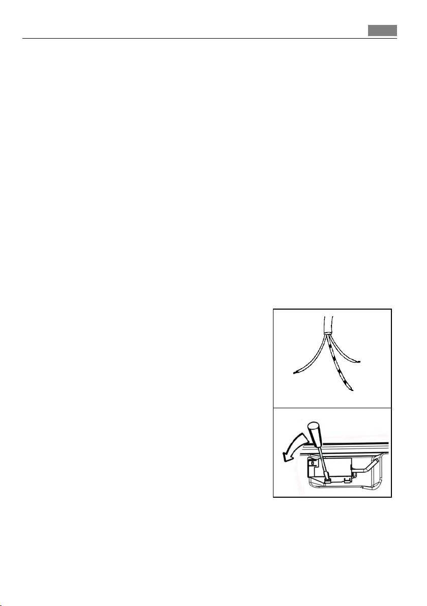
Remplacement of the voltage cable
The connection of the voltage cable to
the appliance's terminal block is of type "Y".
This means that its replacement requires the
specific equipment of a technician. In this
case, only cable type H05V2V2-F T90 must be
used. The cable section must be suitable to
the voltage and the working temperature.
The yellow/green earth wire must be
approximately 2 cm. longer than the phase
wires (Fig. 3-a).
To open the terminal block and reach the
terminals, proceed as follows:
• insert the point of a screwdriver into the
visible protrunding part of the terminal
block;
• exert a light pressure and lift (Fig. 3-b)
Neutral
Earth
Fig. 3-a
Fig. 3-b
(yellow/green))
16
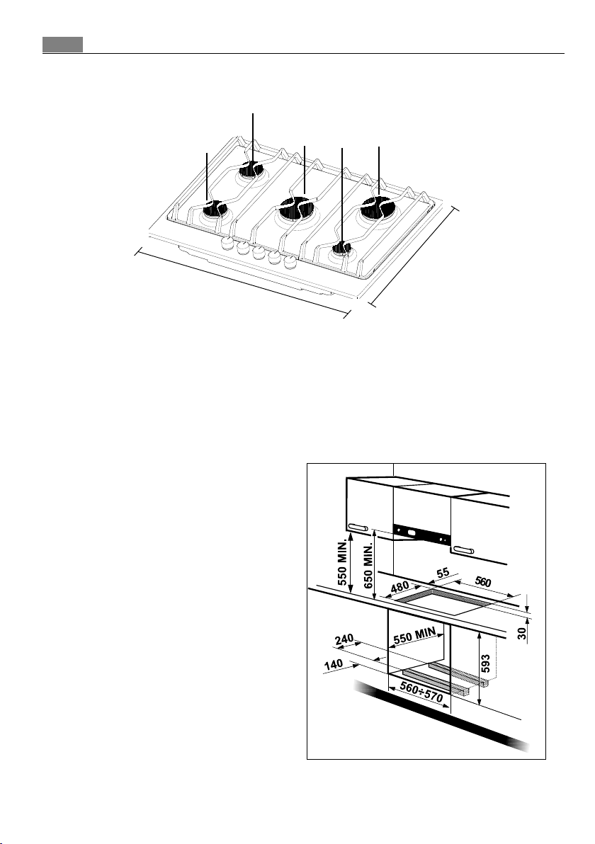
Building In
SR
SR
744
A = Auxiliary burner
SR = Semi-rapid burner
R = Rapid burner
TC = Triple Crown burner
These hobs can be inserted in a built-in
kitchen unit whose depth is between 550 and
600 mm. The hobs dimensions are shown in
Fig. 4.
The edge of the cut out must have a
minimum distance from the rear wall of 55
mm.
If there are side walls, or sides of the
furniture unit near the hob, the cut out
edges must have a minimum distance of 150
mm.
Hanging forniture units or hoods must be
placed at 650 mm. minimum from the hob.
TC
Dimensions are given in millimeters
A
R
510
Fig. 4
Fig. 5
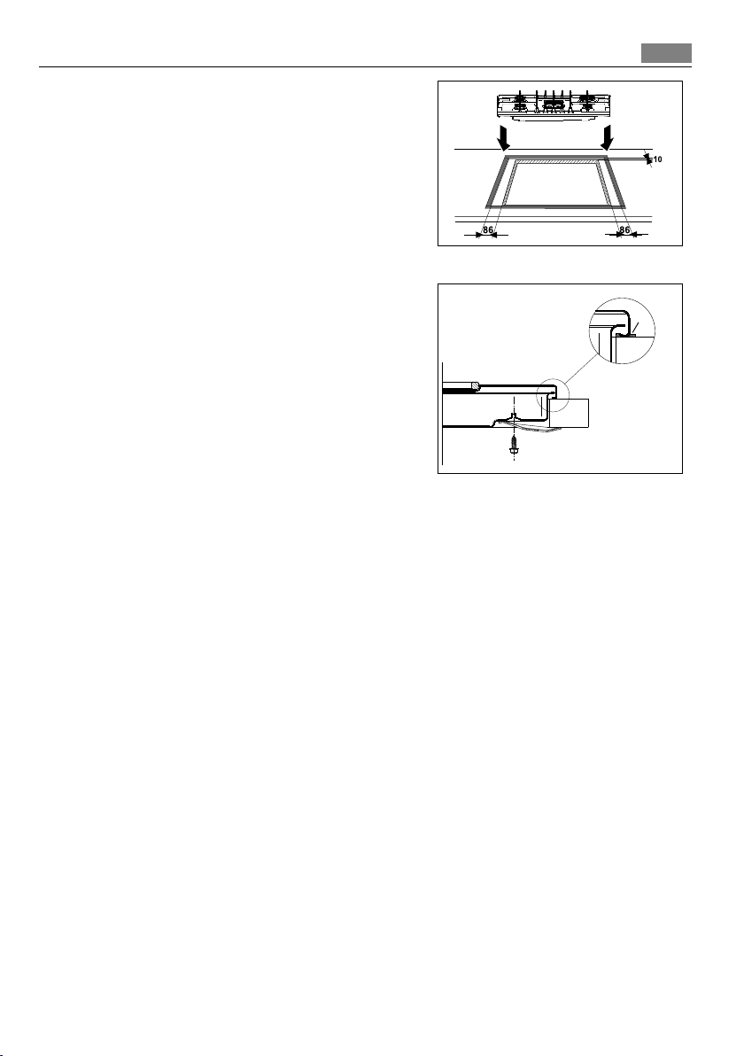
Fitting the hob to the worktop
Carry out the building in of the hob as
follows:
1. Place the seals supplied with the hob on
the front edge of the cut out. Then, place
them at 86 mm from the side edges and
at 10 mm from the rear edge, as shown in
the diagram, taking care that the seals
meet without overlapping.
2. Place the hob in the cut out, taking care
that it is centred.
3. Fix the hob with the relevant fixing
clamps, supplied with the injectors kit
(see diagram). When the screws have
been tightened, the excess seal can be
removed.
The edge of the hob forms a double seal
which prevents the ingress of liquids.
17
Fig. 6
a
a) seal
Fig.7
18
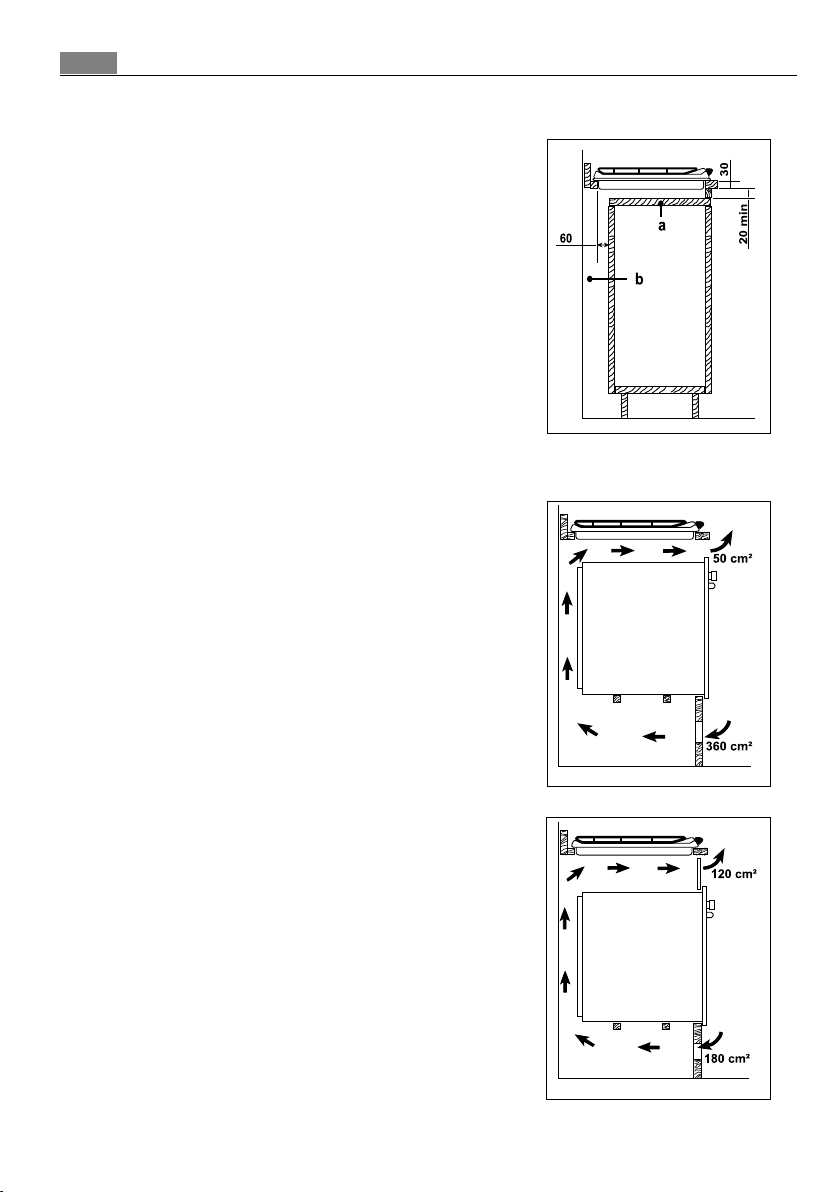
Possibilities for insertion
Kitchen unit with door
Proper arrangements must be taken in
designing the forniture unit, in order to avoid
any contact with the bottom of the hob
which can be heated when it is operated. The
recommended solution is shown in Fig. 8. The
panel fitted under the hob should be easily
removable to allow an easy access if a
technical assistance intervention is needed.
Kitchen unit with oven
The hob recess dimensions must comply
the indication given in Fig. 5 and must be
provided with brackets to allow a continuous
supply of air. To avoid overhating, the
building in should be carried out as shown in
Figs. 9 e 10. The hob's electric connection and
the oven's one must be carried out
separately, both for safety reasons and to
allow the oven to be easily taken off the unit.
Fig. 8
a) Removable panel
b) Space for connections
Fig. 9
Fig. 10

19
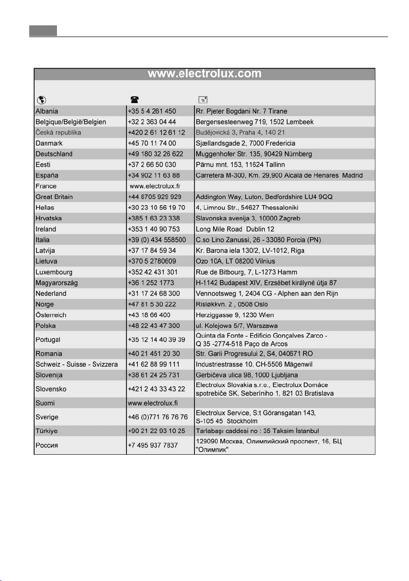
European guarantee
This appliance is guaranteed by Electrolux in each of the countries listed at the back of this user
manual, for the period specified in the appliance guarantee or otherwise by law. If you move from
one of these countries to another of the countries listed below the appliance guarantee will move
with you subject to the following qualifications:
• The appliance guarantee starts from the date you first purchased the appliance which will be
evidenced by production of a valid purchase document issued by the seller of the appliance.
• The appliance guarantee is for the same period and to the same extent for labour and parts as
exists in your new country of residence for this particular model or range of appliances.
• The appliance guarantee is personal to the original purchaser of the appliance and cannot be
transferred to another user.
• The appliance is installed and used in accordance with instructions issued by Electrolux and is
only used within the home, i.e. is not used for commercial purposes.
• The appliance is installed in accordance with all relevant regulations in force within your new
country of residence.
The provisions of this European Guarantee do not affect any of the rights granted to you by law.
20

21
Благодарим вас за то, что выбрали одно из наших высококачественных
изделий.
Чтобы обеспечить оптимальную и бесперебойную работу прибора, внимательно
прочитайте настоящее Руководство. Это позволит выполнять все операции
наиболее правильным и эффективным образом. Для того чтобы в нужный
момент всегда можно было свериться с настоящим Руководством, рекомендуем
хранить его в надежном месте. Просим также передать его новому владельцу
прибора в случае продажи или уступки.
Надеемся, что новый прибор доставит вам много радости.
 Loading...