


AMM12N
Installation and Operation Manual
Press Audio |
AMM12N |
Enter |
DIV ®
video
240 |
Watts Peak |
|
Watts en Crête |
||
|
||
|
Vatios el Máximo |
|
|
60W x 4 |

AMM12N
CONTENTS
Thank you for choosing an Advent product. We hope you will find the instructions in this owner’s manual clear and easy to follow. If you take a few minutes to look through it, you’ll learn how to use all the features of your new Advent AMM12N Mobile Multimedia Receiver for maximum enjoyment.
Preparation............................................................................................................................ |
1 |
Installation ............................................................................................................................. |
5 |
Anti-Theft Feature ................................................................................................................. |
7 |
Controls and Indicators ......................................................................................................... |
8 |
Remote Control ................................................................................................................... |
10 |
Using the TFT Monitor ........................................................................................................ |
14 |
Operating Instructions ......................................................................................................... |
15 |
Multi-ZONE Operation......................................................................................................... |
17 |
Setup Menu......................................................................................................................... |
18 |
Tuner Operation .................................................................................................................. |
21 |
Satellite Radio Operation .................................................................................................... |
23 |
DVD/VCD Video Operation ................................................................................................. |
25 |
DVD/CD Audio Operation ................................................................................................... |
28 |
MP3/WMA Operation .......................................................................................................... |
29 |
iPod Operation .................................................................................................................... |
31 |
Bluetooth Operation ............................................................................................................ |
32 |
Troubleshooting .................................................................................................................. |
35 |
Specifications ...................................................................................................................... |
38 |
i

AMM12N
ii

AMM12N
PREPARATION
Congratulations on your purchase of the Advent AMM12N Mobile Multimedia Receiver.
It’s a good idea to read all of the instructions before beginning the installation. We recommend having your Advent AMM12N installed by a reputable installation shop.
Features
DVD
•Aspect Ratio – Cinema and Normal
•Fast Forward / Reverse – 2X, 4X, 8X and 32X
•Play, Pause, Stop, Next Chapter and Previous Chapter
•ESP – 2MB Buffer
CD / MP3 / WMA
•ID3 Tag Compatible
•Directory Search (MP3 / WMA Only)
•Direct Track Access via Remote control
•Burn up to 1500 MP3 and WMA Files onto a DVD+R / RW
•Audible Forward / Reverse Track Search
•Random, Repeat and Intro
•Play, Pause, Stop, Next Track and Previous Track
•ESP – 2MB Buffer
AM-FM
•USA/Europe/Latin America/Asia Frequency Spacing
•30 Station Presets (18 FM, 12 AM)
•Auto Stereo/Mono
•Local/Distance
•Auto Store/Preview Scan
•RDS (Radio Data System)
Sat Radio Ready
•Compatible with XM and Sirius Tuners (Sold Separately)
•Requires XMDJEN100 or JXMC Cables for XMD1000 Only (Sold Separately)
•Satellite Channel Name, Artist, Song and Categories Displayed on TFT Screen
iPod
•jLinkDirect - High Speed Direct Connect Interface to Access iPod Playlists, Artists, Albums, Songs, Photos** and Video**. (Requires Gen 5.5 or earlier photo or video iPod. iPod Touch, iPod Classic and iPod Nano with video will only play music files.)
•Power Management Charges iPod while Connected
•Requires jLinkCable iPod Interface Cable (included)
MediaLink4
•Under Dash Interface Allows Portable Media Devices to be Connected
•MediaLink4 Includes the Following Connectivity:
•USB – Supports Flash Memory and Hard Drives with Audio Files
•LinkDirect iPod Connectivity
•3.5mm Audio Only Input
•RCA Audio /Video Input
Chassis
•2.0 DIN (Import / ISO-DIN Mountable)
•Motorized Swing-Down LCD Screen
•6.5" TFT Active Matrix LCD with Anti-Glare Coating
•Screen Tilt / Angle Adjustment
•Heat Management System - Forced Air-Cooling to Keep the Chip-Sets Operating at Nominal Temperatures
General
•Bluetooth – Bluetooth hands-free profile for safety / convenience and A2DP profile for streaming music from a PDA / PMP
•Navigation Ready (AMN101 Only)
•38-Key Infrared Remote Control with 5-way Joystick
•Two Composite Video Outputs for Additional Screens
•Compatible with MZ7-TFT Rear Seat Monitors with Touch Screen Interface
•Two Audio /Video Auxiliary Inputs
•200-Ohm Preamp Line Output – All Audio Channels
•4VRMS Line Output – All Channels
•Rotary Encoder Audio Control
•Seven-Band EQ with Eight Preset EQ Curves
•Spectrum Analyzer
•Front, Rear, Center and Subwoofer Line Output
•Built-In Integrated Center Channel Amplifier (40 Watts X 1)
•Subwoofer Crossover and Phase Control
•Dolby Digital / Pro-Logic ll
•Programmable Volume Control
•Rear Camera Input (Normal and Mirror Image View)
•5-Way Joystick
AMN101
The AMM12N is "navigation ready." Before accessing any navigation features, you must install the AMN101 module. All installation and operating instructions are included with the AMN101 navigation module.
Once the AMN101 is connected and operating properly, the NAV source mode will become active. While the AMN101 is not installed, the NAV option appears gray, indicating the function is not available.
1

AMM12N
What’s in the Box
1.Left and Right Double DIN Mounting Brackets
2.Double DIN Half Sleeve Install Bracket
3.Remote Control with Battery
4.Rear Support Mounting Strap
5.iPod Jlink Cable
6.Two Custom Cosmetic Trim Rings
7.Parking Brake Wire
8.MediaLink Box
9.Screen Cleaning Cloth
10.M5x6 and M3x4 Screws to Mount Radio to Brackets
11.Speaker Output Harness
12.Power Input Harness
13.Center Channel Wire Harness
Optional Equipment
•Rear Camera
The AMM12N is "camera ready." Before accessing any camera features, you must purchase and install a rear video camera. Once the rear camera is connected and operating properly, the CAMERA source mode will become active. While the camera is not installed, the CAMERA option appears gray, indicating the function is not available.
•Satellite Radio Tuner
See “Satellite Radio Operation” on page 23.
•jLinkCable and iPod
See “MP3/WMA Operation” on page 29.
•Bluetooth Phone
See “Bluetooth Operation” on page 32.
•3.5mm to 3.5mm Audio Cable
Sold separately at various retailers.
Tools and Supplies
You will need these tools and supplies to install your AMM12N:
•Torx type, flat-head and Philips screwdrivers
•Wire cutters and strippers
•Tools to remove existing radio (screwdriver, socket wrench set or other tools)
•Electrical tape
•Crimping tool
•Volt meter/test light
•Crimp connections
•18 gauge wire for power connections
•16 – 18 gauge speaker wire
Disconnecting the Battery
To prevent a short circuit, be sure to turn off the ignition and remove the negative (-) battery cable prior to installation.
NOTE: If the AMM12N is to be installed in a car equipped with an on-board drive or navigation computer, do not disconnect the battery cable. If the cable is disconnected, the computer memory may be lost. Under these conditions, use extra caution during installation to avoid causing a short circuit.
WARNING! Only connect the unit to a12-volt power supply with proper grounding.
WARNING! Never install this unit where operation and viewing could interfere with safe driving conditions.
WARNING! To reduce the risk of a traffic accident (except when using for rear view video camera) never use the video display function while driving the vehicle. This is a violation of federal law.
WARNING! Never disassemble or adjust the unit.
WARNING! To prevent injury from shock or fire, never expose this unit to moisture or water.
WARNING! Never use irregular discs.
WARNING! To prevent damage to the mechanism inside this unit, avoid impact to the TFT monitor.
WARNING! Using an improper fuse may cause damage to the unit and result in a fire.
2

AMM12N
WIRING DIAGRAM
Media Module Cable / BLACK
AMN101 Input
Separately) |
|
Camera |
External |
|
*NOTE: |
|
|
|
|
|
See the |
|
|
|
|||
MZ7-TFT Touch |
|
|
A/V System |
|
|
|
|
|
Screen (Sold |
YELLOW |
ViewRearVideo |
|
|
|
|
|
|
BLACK |
|
|
Multimedia |
|
|
|
||
NAV Bus |
|
|
|
|
|
|
|
|
|
|
|
|
|
Connections |
|
|
|
|
|
|
|
|
Diagram for |
|
|
|
|
|
YELLOW |
WHITE |
RED |
additional |
YELLOW |
WHITE |
RED |
|
|
MediaLink. |
||||||
|
|
|
|
|
connections |
|
|
|
|
|
|
|
|
through the |
|
|
|
MZ7-TFT |
|
|
|
|
|
|
|
|
|
|
CAMERA |
AUX IN 2 |
|
|
|
AUX IN 1 |
|
|
|
|
|
|
|
|
|
|
|
|
|
|
|
|
|
(-)BROWN |
|
|
|
|
ANT.CONT |
|
|
|
|
SATRadio |
SATR |
SATL |
|
CENTER |
SUBWOOFER |
REAR |
RSURROUND |
REAR |
LSURROUND |
FRONT R |
FRONT L |
VIDEOOUT1 |
2VideoRear |
VIDEOOUT2 |
|
|
|
|
|
|
|
MUTE |
|
|
|
BLUE |
YELLOW |
GREEN |
BLUE |
|
|
WHITE |
|
|
|
|
|
|
|
|
1VideoRear |
YELLOW |
YELLOW |
|||
|
|
|
|
|
|
Cell Phone |
|
|
|
|
|
|
|
|
|
|
RED |
|
|
|
|
|
|
|
|
|
|
|
|
|
|
|
|
|
|
|
|
|
|
|
|
|
|
|
|
|
|
|
|
* Satellite |
|
|
|
|
|
|
|
|
|
|
|
|
|
|
|
|
|
|
|
|
|
|
|
|
|
|
|
|
|
|
|
Receiver |
|
|
|
|
|
|
|
|
|
|
|
|
|
|
|
|
|
|
|
|
|
|
|
|
|
|
|
|
|
|
|
Connections |
|
|
|
|
|
|
|
|
|
|
|
|
|
|
Auto Antenna |
|
|
|
|
|
|
|
|
|
|
|
|
|
|
|
|
|
|
|
|
|
|
|
|
|
|
|
|
|
|
L |
GREEN(+) WHITE/BLACK(-) |
WHITE(+) FRONTL |
GREY/BLACK(-) FRONTR |
GREY(+) |
PURPLE(+) |
R |
SWITCHIGNITION |
ACC |
RED |
YELLOW |
FILTER/FUSE (20A) |
BLACK |
|
BROWN/BLACK(-) |
BROWN(+) |
PINK(-) |
PRKSW |
GREEN/WHITE(+) |
REVERSE |
GREY |
BLUE |
|
RED |
WHITE |
|
RED |
|
WHITE |
|
|
|
GREEN/BLACK(-) |
)-PURPLE/BLACK( |
|
GND |
|
|
|
|
|
|
|
|
|
PowerExternalAmplifier |
|
|
|
|||||||||||||||
REAR |
|
|
|
|
|
REAR |
|
|
|
|
BATT |
|
|
|
CENTER |
|
|
|
|
|
|
BLUE/WHITE |
|
|
|
|
|
|
|
||
|
|
|
|
|
|
|
|
|
|
|
|
|
|
|
|
|
|
|
|
|
|
P.CONT |
|
|
|
|
|
|
|
|
|
|
|
|
|
|
|
|
|
|
|
|
+ |
- |
|
|
|
|
|
|
|
|
|
|
|
|
|
|
|
|
|
|
|
|
|
|
|
|
|
|
|
|
|
|
BATTERY |
|
|
|
|
|
|
|
|
|
|
|
|
|
|
|
|
|
|
|
|
|
|
|
|
|
|
|
|
|
|
|
|
|
|
|
|
|
|
3 |
|
|
|
|
|
|
|
|
|
|
|
|
|
*MediaLink
HEADPHONE
MULTIZONE
RED |
WHITE |
WIRELESS HEADPHONE (OPTIONAL)
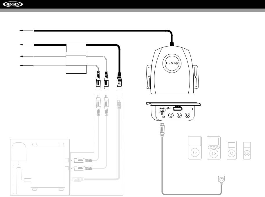
AMM12N
MEDIALINK AND SATELLITE CONNECTIONS
Unit |
|
|
Head |
SAT Radio |
|
|
||
To |
SAT L |
|
SAT R |
||
|
Compatible SAT Tuners:
1.XMD1000 (requires XMC or XMDJEN100 Cable Kit)
2.CNP2000UC
3.SC-C1 and SIRJEN2
**
*
|
*** Requires Gen 5.5 or |
MediaLink |
earlier photo or video |
|
iPod. iPod Touch, iPod |
|
Classic and iPod Nano |
3.5mm - Audio VIDEO LEFT RIGHT |
with video will only play |
|
|
|
music files. |
iPod Video |
iPod |
|
|
|
|
iPod Mini iPod Nano |
||||||
|
|
|
|
|
|
|
|
|
|
|
|
|
|
|
|
|
|
|
|
|
|
|
|
|
|
|
|
|
|
|
|
|
|
|
|
|
|
|
|
|
|
|
|
|
|
|
|
|
|
|
|
|
|
|
|
|
|
|
|
|
|
|
|
|
|
|
|
|
|
|
|
|
|
|
|
|
|
jLink iPod Cable
(Included)
4
AMM12N
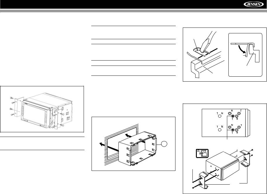
INSTALLATION
ISO DIN Installation
This unit is designed to fit into a 2.0 DIN dashboard opening, found in many imported cars. The unit has threaded holes in the chassis side panels which may be used with the original factory mounting brackets of some Toyota, Nissan, Mitsubishi, Isuzu, Hyundai and Honda vehicles to mount the radio to the dashboard. Please consult with your local car stereo specialty shop for assistance on this type of installation.
1.Remove the existing factory radio from the dashboard or center console mounting. Save all hardware and brackets as they will be used to mount the new radio.
2.Remove the factory mounting brackets and hardware from the existing radio and attach them to the new radio.
ISO INSTALLATION
CAUTION: Do not exceed M5 X 6MM screw size. Longer screws may touch and damage components inside the chassis.
3.Place the radio in front of the dashboard opening so the wiring can be brought through the mounting sleeve. Follow the wiring diagram carefully and make certain all connections are secure and insulated with wire nuts or electrical tape. After completing the wiring connections, plug the ISO connectors into the mating sockets on the rear of the chassis. Turn the unit on to confirm operation (vehicle ignition switch must be “on”). If the unit does not operate, re-check all wiring until the problem is corrected.
4.Mount the new radio assembly to the dashboard or center console using the reverse procedure in step 1.
CAUTION: For proper operation of the CD player, the chassis must be mounted within 30° of horizontal. Make sure the unit is mounted within this limitation.
NOTE: It is the end-users responsibility to install and operate this unit in a manner in accordance with local, state and federal laws. The PARKING BRAKE wire MUST BE CONNECTED as directed in the manual.
CAUTION: Do not block the cooling fan exit. If blocked, the unit may overheat and become damaged.
Installation Using Half-Sleeve
1.Press the metal levers on both sides to remove the halfsleeve from the radio.
2.Install the half-sleeve.
a.Install adapter if necessary (optional).
b.Install half-sleeve into adapter or dashboard (use only the supplied screws). Do not force the sleeve into the opening or cause it to bend or bow.
INSTALL HALF SLEEVE
2b
c.Locate the series of bend-tabs along the top, bottom and sides of the mounting sleeve. With the sleeve fully inserted into the dashboard opening, bend as many of the tabs outward as necessary so that the sleeve is firmly secured to the dashboard.
TAB
TAB
DASHBOARD
DASHBOARD
3.Use the M5 x 6 screws (provided) to install the mounting brackets to each side of the radio using the holes indicated below.
Install Bracket Here
Non-Designated
Screw Prohibited
M5X6
SCREW
BRACKET
4.Place the radio in front of the dashboard opening so the wiring can be brought through the mounting sleeve.
5
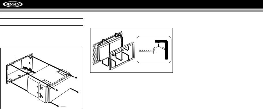
AMM12N
CAUTION! Be careful not to damage the car wiring.
5.Complete wiring as illustrated in the wiring diagram on page 3. Once the wiring is complete, reconnect the battery negative terminal. If there is no ACC available, connect the ACC lead to the power supply with a switch.
MOUNTING SLEEVE |
M3x4 |
SCREW |
After completing the wiring connections, turn the unit on to confirm operation (ignition switch must be on). If unit does not operate, recheck all wiring until problem is corrected. Once proper operation is achieved, turn off the ignition switch and proceed with final mounting of the chassis.
1.Connect wiring adapter to existing wiring harness.
2.Connect antenna lead.
3.Carefully slide the radio into the half-sleeve, making sure it is right-side-up, until it is fully seated and the spring clips lock it into place.
Using the Cosmetic Trim Ring
Two cosmetic trim rings are packaged with the AMM12N for installation flexibility. The AMM12N will fit into most import dashes with little or no modification to the dash board/cavity. Some US domestic vehicle dashes will accept a Double-DIN chassis, but there is usually a small gap between the radio and dash piece after installation is complete. In this case, use the appropriate trim ring to conceal any gaps that may be present.
The 4 tabs on the trim ring will snap into four holes on top and bottom of the mounting sleeve.
TRIM RING |
OPTIONAL |
MOUNTING |
TRIM RING |
SLEEVE |
Installing the MediaLink External AV Connector
The MediaLink allows you to connect a variety of external devices, including a VCR, DVD player, portable MP3 player, etc., to your AMM12N without removing the radio.
To install the MediaLink, connect it to the AUX-IN cables on the back of the AMM12N (see the Wiring Diagram on page 3), and then install the MediaLink in a location convenient for plugging in auxiliary devices.
Replacing the Fuse
When replacing the fuse, use a new 20A replacement fuse. Using a fuse with an improper rating could damage the unit and cause a fire.
6
AMM12N
ANTI-THEFT FEATURE
The AMM12N is equipped with an anti-theft feature requiring the user to enter a password upon initial power on.
3.Touch the keypad icon next to the blue box in the “Password” field to open the on-screen keypad.
Enter Password:
1 |
2 |
3 |
4 |
5 |
6 |
7 |
8 |
9 |
0 |
|
|
Entering the Default Password
The default user password is 012345 (6 digits). Enter the password using the on-screen keypad and then press the Enter (arrow) button. You can also use the remote control keypad to enter the password.
RADIO |
SETUP MENU |
02:40 AM |
||||
General |
Language |
Audio |
Speaker |
Bluetooth |
Back |
|
RDS |
Password |
|
|
1 |
2 |
3 |
Rating |
|
|
||||
Rating |
|
8. Adult |
|
|
|
|
DivX |
|
4 |
5 |
6 |
||
|
|
|
|
|
|
|
Hardware |
Load Factory |
Reset |
7 |
8 |
9 |
|
|
|
|
||||
P.VOL |
|
|
|
0 |
Clear |
|
TS Cal |
|
|
|
|
|
|
4.Enter a new 6-digit password and press the Enter (arrow) button.
The "lock" icon will now appear closed and the new antitheft password will be set, as well as the password for RATING protection (see “Rating Sub-menu Features” on page 19).
NOTE: If you forget your password, contact Customer Service at 1-800-645-4994 for assistance.
Press the joystick Enter button (18) on the remote control to confirm.
Changing the Password
To change the anti-theft and RATINGS protection password, perform the following steps:
1.Press the SETUP button (31) on the remote control or
touch the  button on the screen to enter the “SETUP” menu.
2.Touch RATING to view the “RATING” sub-menu. An open lock icon to the right of the “Password” field indicates that a user password had not yet been entered.
7
AMM12N
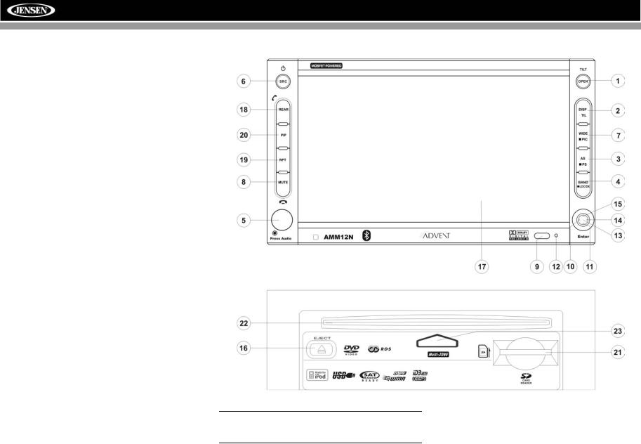
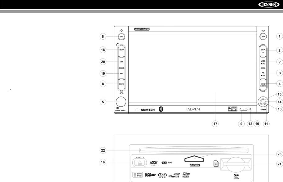
CONTROLS AND INDICATORS
Button Operation
1. OPEN/TILT
Press to activate the automatic mechanical system and move the TFT monitor into viewing position. Press again to close the TFT.
Press and hold to activate the screen tilt function (use the joystick to adjust the angle).
2. DISP
Press to cycle through information available on the TFT screen.
In DVD Mode, press to view the top and bottom information bars. Press again to turn “Display Off”.
When the AMN101 is connected to the AMM12N, press and hold to display the navigation user interface. You will still be able to listen to your music source; however, any navigation voice prompts will mute the music source temporarily. The TFT screen must be open for this function to operate.
3. AS/PS
Press to automatically store the first six strong stations in preset memory. Applies to current band only.
4. BAND/LOC/DX
Press the BAND button to change the AM, FM or SAT band. Press and hold to turn strong local reception on/off.
5. AUDIO
Rotate to adjust the volume. Press to enter and/or confirm audio settings.
6. SRC
Press to select playing mode.
When you change the source during navigation, the voice prompts will still be heard, although the navigation map cannot be seen. (The selected source audio will be muted until the navigation voice prompt command is completed, after which the source audio will resume.)
7. WIDE/PIC
Press to adjust the display aspect of the picture to one of three settings: CINEMA, NORMAL or Standby (screen off). Touch the screen to turn Standy mode off. NOTE: Only CINEMA and Standby are available for non-video sources.
Press and hold to adjust Brightness and Contrast.
8. MUTE
Press to silence the receiver. Press again to resume the previous volume level.
BT Mode: Answer/dial Bluetooth call.
NOTE: The AMM12N features Softmute, which will allow the volume to increase or decrease gradually when the MUTE function is activated or deactivated.
9.IR Remote Control Receiver
10.(left joystick)
DVD/Disc Mode: Press once to play back the previous chapter/track.
TUNER Mode: Press once to auto-search for the previous available radio station.
MENU Mode: Press once to move the cursor to the left.
11. (down joystick)
DVD/Disc Mode: Press once for slow forward/slow reverse. TUNER Mode: Press to go down one frequency step. MENU Mode: Press once to move the cursor down.
12. Reset
Press to reset system settings to factory default (except the password and parental lock setting).
8
AMM12N
CONTROLS AND INDICATORS
13.Pause/Play/Enter
Press to pause or resume playback or to confirm current selection.
14. (right joystick)
DVD/Disc Mode: Press once to enter the next chapter or track.
TUNER Mode: Press once to auto-search the next available radio station.
MENU Mode: Press once to move the cursor to the right.
15. (up joystick)
DVD/Disc Mode: Press once for fast forward/fast reverse. TUNER Mode: Press to go up one frequency step. MENU Mode: Press once to move the cursor up.
16. ( )
)
Press once for disc insertion/ejection.
Press and hold to reset core mechanism position.
17.TFT Display
18.REAR
Select rear zone source. Allows front passengers to listen to the radio while rear passengers listen to a CD, MP3, WMA or watch DVDs.
BT Mode: Disconnect Bluetooth call.
19. RPT
Press to control repeat playback function.
20. PIP
Press to activate the Picture In Picture function.
AMN101: Press and hold to return to the AMN101 user interface.
21. SD Card Slot
Insert SD card for playback of audio files.
22. Disc Slot
Insert CD or DVD for playback.
23. Disc Loaded indicator
Red indicates disc is loaded. Blue indicates disc slot is empty.
9

AMM12N
REMOTE CONTROL
The AMM12N Remote controls both the front and rear zones. To switch from front to rear zone, move the F/R switch (32) located on the right side of the controller.
10
 Loading...