

Page 1
Spectrum Analyzers
Compact Design with High Performance
Pioneering 3 GHz/8 GHz Spectrum Analyzers are Now Available!
U3741/3751
Page 2

The U3741/3751 portable spectrum analyzer
supports a great range of applications, from
use on production lines to system installation
and maintenance. Its digital IF enables dramatic
improvements in power measurement accuracy
for digitally modulated signals. Moreover, the
U3741/3751 provides twice the throughput of its
predecessor. A light and compact 3 GHz/8 GHz
spectrum analyzer, the U3741/3751 provides ba-
sic performance reliably and at a low cost.
●
Better measuring speed due to high-speed processing
(twice as fast as its predecessor)
●
Dramatically improved power measurement accuracy
for digitally modulated signals
●
Built-in 3 GHz/8 GHz pre-amp standard
●
Average display noise level:
-155 dBm/Hz@1 GHz, pre-amp ON
●
Tracking generator covering a frequency range of
100 kHz to 3 GHz
●
Option available for measurement of phase noise
characteristics
●
Lightweight and compact design, with a maximum
weight of only 5.6 kg
●
Continuous operation of up to 2.5 hours with the
battery pack
U3741/ 3751 Web Demonstration
Please access to the http://www.advantest.co.jp/en-index.shtml and click on the following links.
PRODUCTS & SUPPORT Electronic Measuring Instruments Products U3751
2
U3741/3751-1E Mar. ’07
Page 3
75 Ω Input Impedance
Option Guide
● —
OPT.15
Used for measurement of CATV and TV signals
Product name
Main unit support
U3741
(9 kHz to 3 GHz)
U3751
(9 kHz to 8 GHz)
Model number Overview
High-Stability Frequency
Reference Source
●●
OPT.20
High-stability reference oscillator with an aging
rate of ± 2 x 10
-8
/day, ±1 x 10⁻⁷/year
EMC Filter
●
1)
●
1)
OPT.28
CISPR bandwidths are available for EMI
measurement.
RBW (6 dB down): 200 Hz, 9 kHz, 120 kHz, 1 MHz
High-Purity
Spectrum Analysis
●
1)
●
1)
OPT.70
High-purity spectrum analysis with -100 dBc/Hz
@ 10 kHz offset
RBW 30 Hz has also been added.
75 Ω Tracking Generator
●
2)
—
OPT.75
Used for evaluation of frequency characteristics
in a range from 100 kHz to 2.2 GHz.
Output power range: 107 to 47 dBµV
50 Ω Tracking Generator
●
1)
●
1)
OPT.76
Used for evaluation of frequency characteristics
in a range from 100 kHz to 3 GHz.
Output power range: 0 to -60 dBm
1) OPT.15 and OPT.75 cannot be installed simultaneously. 2) OPT.15 is required, and cannot be installed simultaneously with OPT.76.
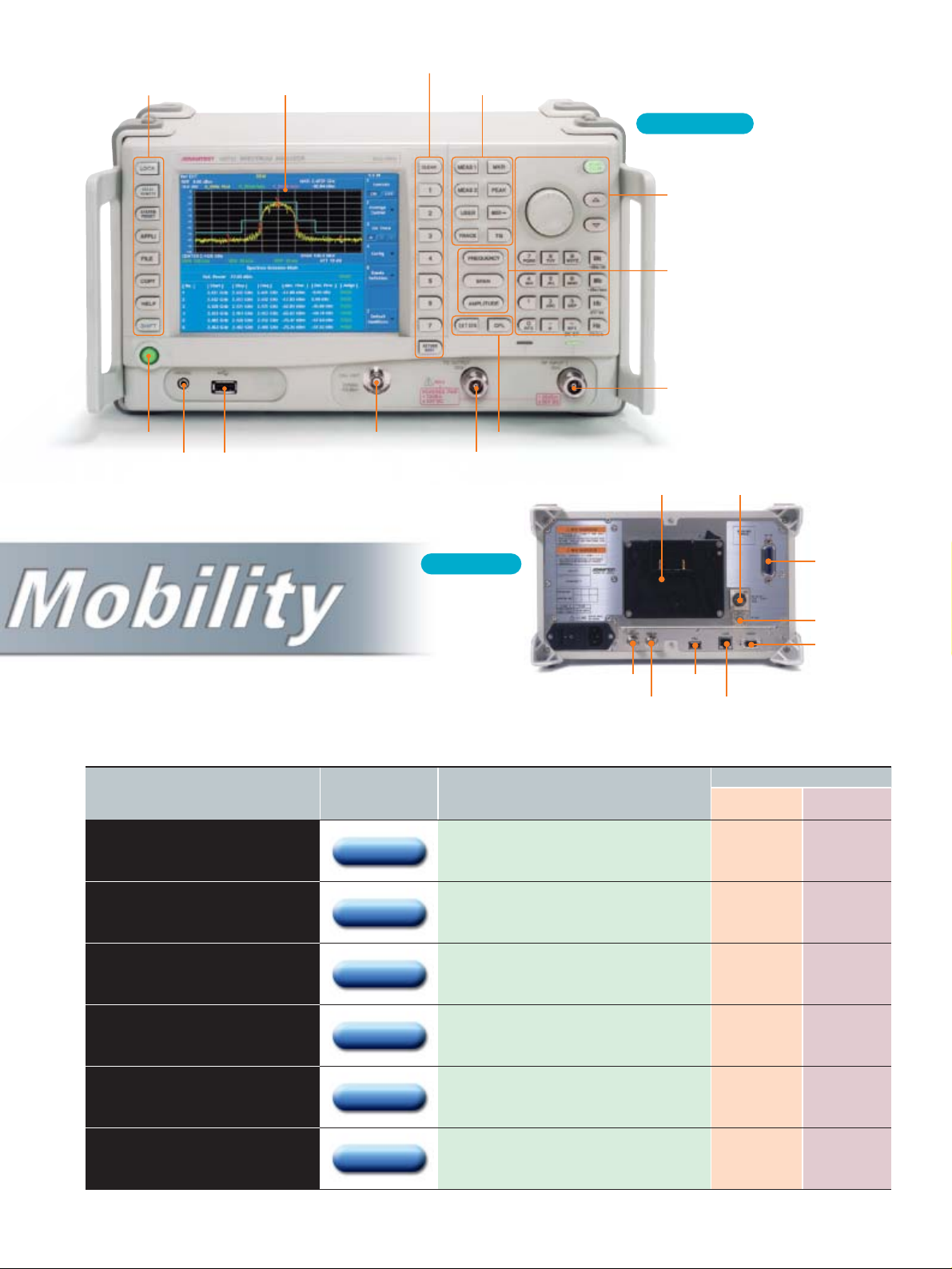
IF OUT
21.4-MHz IF
signal output
VIDEO
Output to an
external VGA
monitor
Main function keys
Data Entry
GPIB
EXT TRIG USB
POWER CAL OUT
Soft-key block
RF INPUT
Control keys
EXT REF
Standard signal input
for external reference
LAN
Control and remote operation,
utilizing an external PC
6.5-inch color liquid
crystal display (LCD)
Exclusive function keysExtension-key block
Front Panel
Rear Panel
USB
Output file data to USB
memory or a USB printer
Image files: PNG, BMP
Setting files: BIN, XML
TG OUT
Tracking generator
(option)
Battery mount
Mount for the battery pack
(battery sold separately)
DC INPUT
Operation with an external
DC power supply
+11 VDC to +17 VDC
PHONE
Earphone jack for
demodulated
AM/FM audio
U3741/3751-1E Mar. ’07
3
Page 4
4
U3741/3751-1E Mar. ’07
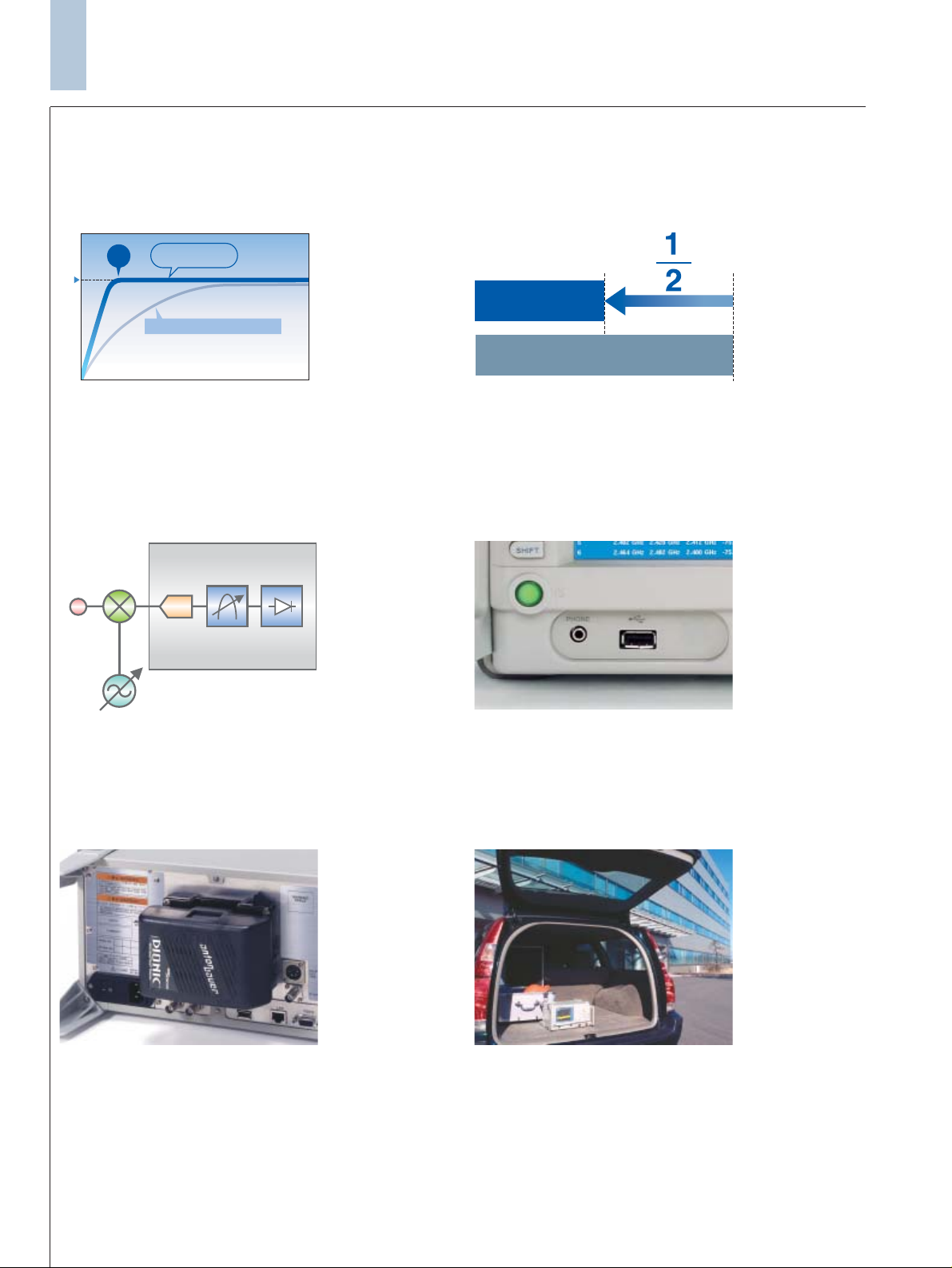
5-minute warm-up time
With the U3741/3751, warm-up time has been reduced to a scant
5 minutes (at an ambient temperature of 20 to 30°C). This shortened period virtually eliminates pre-warming time as a consideration, and permits quick and accurate measurement.
High throughput
This spectrum analyzer delivers data transfer speed superior to that
of its predecessor. While the previous model delivered 875 ms, the
U3741/3751 boasts a speed of 350 ms: double the system throughput
*2
(using the GPIB interface)*3. This faster speed contributes to
a significant reductions to cost of test on production lines and in
similar applications.
Compact Design with High Performance
Our conventional model
U3741/3751
Time
Stable measurement
5
min.
Measuring time
Our conventional model
U3741/3751
Improvements in overall accuracy
Digitized IF sections and innovative circuit technology dramatically
improve absolute power measurement accuracy.
±0.8 dB (10 MHz to 3 GHz: U3741/3751)
±1.0 dB (3 to 8 GHz: U3751)
Standard USB (1.1) interface
Screenshots in BMP or PNG format can easily be sent via USB
external memory. Users can easily store data, and easily paste measurement data into reports.
ADC Digital RBW Digital Det
Digital IF Block
RF Input
Up to 2.5 hours*1of nonstop battery-driven operation
The spectrum analyzer uses one of three power systems: AC (100
V/200 V), DC (+11 V to +17 V), or the battery pack. This flexibility enables measurement in a variety of applications, whether in
the factory or in the field.
Compact design
At about half the size of its predecessor, this spectrum analyzer
offers a compact design while maintaining the same level of functionality. Its form factor gives it portability, enabling it to be used
anywhere.
*1: Typical value at room temperature, without options
*2: Twice that of its predecessor
*3: Sample case where the frequency and span are specified, and the channel power measurement
result is transferred
Extensive array of measurement functions
Measurement functions include Channel Power, Total Power,
Avg Power, OBW, ACP, Spurious measurement, Harmonics measurement, IM measurement, Noise/Hz calculation functions,
multi-marker (10 markers), delta marker, peak marker functions,
a channel setting function, and a 3-trace simultaneous sampling
function.
Page 5

U3741/3751-1E Mar. ’07
5
RMS Average, essential for power measurement
Power tends to be spread over a wide frequency range, and the peak
factor tends to be higher in digital modulation, with it’s expanded
communication capacity. The U3741/3751 allows precise power
measurements by determining the effective values (RMS values)
from instantaneous power values obtained in high-speed sampling
and translating them into a power spectrum. This method also
enables measurement reproducibility of 0.01 dB in power measurement of digitally modulated signals.
Pre-Amp covering the 3 GHz/8 GHz bandwidth
The U3741/3751 contains as standard a pre-amp that covers all
frequency bands. In the analysis of faint signals, its input sensitivity can be equivalent to that of high-end models. Also, it effectively compensates for the loss from the antenna when measuring
radio signals in an outdoor environment.
Measurement Functions
Built-in frequency counter with 1-Hz resolution
Frequency can be accurately measured by simply positioning the
cursor on the target spectrum selected from multiple spectral lines.
The U3741/3751 is indispensable for measuring the carrier wave
frequency in a general multi-carrier system.
Example of ISDB-T
Channel Power
measurement
Example of multicarrier signal frequency
measurement
Example of highsensitivity measurement
in high-sensitivity mode
USER keys
An arbitrary key can be selected from the hierarchical function
keys and assigned to a USER function. Users can thus configure
their own, original setup for operations by assigning frequently
used functions to specific software keys.
Example of
user function
assignment
Zoom function
The measuring window and F-F mode can facilitate analysis of a
specific signal in broadband measurement. Also, RBW can be
changed independently, enabling high-speed measurement of the
target signal in both broadband and narrowband. A variety of
other signal analysis functions are also available, including those in
F-T mode or T-T mode.
Example of two-screen
sample from
measurement in
broadband and
narrowband
Spectrum emission mask function
Using tools such as a spectrum mask and limit line to judge
PASS/FAIL is effective at improving production line throughput
for digital appliances. Using the spectrum emission mask (SEM)
function can facilitate measurement for standards such as wireless
LAN.
Example of S.E.M.
measurement for
wireless LAN
Page 6

6
U3741/3751-1E Mar. ’07
Gated Sweep OFF
User-friendly and Convenient Functions
Burst Signal
Synchronized
signals
RF INPUT
EXT TRIG
Ideal for remote operation/monitoring via a LAN
This spectrum analyzer is equipped with a 10/100BASE-T LAN
port as standard, so it can be operated remotely from an external
PC. It can be installed in an unattended radio transmission station,
and remotely operated and monitored from another station.
LAN
PC
PC
Server
Searching for the location of a fault in a coaxial cable
When used with its tracking generator option and the sample software for an external PC, the U3741/3751 can measure the distance to the failure point (open/short) in a coaxial cable. This
application permits this distance to be measured from one end of
the coaxial cable.
Power splitter
Cable
PC with sample software
GPIB
TG OUT RF INPUT
Screen for measuring the distance to a cable failure point
Screen of remote operation/monitoring from an external PC via LAN
Gated Sweep ON
Gated Sweep function
A radar or TDMA communication system controls its output
transmission by turning the power on/off intermittently. To monitor the power spectrum during transmission, the Gated Sweep
function is effective at analyzing the spectrum only when the signal
is present and over only the area chosen. This function also
includes an IF trigger that does not require synchronized signals.
Page 7

U3741/3751-1E Mar. ’07
7
High-Purity Spectrum Analysis OPT.70
Phase noise measurement is indispensable to evaluation of the
characteristics of high-frequency oscillation circuits or modules.
The high-purity spectrum analysis option offered with the
U3741/3751 can improve the phase noise measurement performance of the spectrum analyzer. Because the performance can be
selected, selecting the most suitable spectrum analyzer for the
device under test (DUT) is simple. At the same time, the added
resolution bandwidth of 30 Hz enables reduction of the display
average noise level and analysis in a high dynamic range.
EMC Filter OPT.28
Option 28 adds 6 dB RBW CISPR bandwidths for EMI measurement of 200 Hz, 9 kHz, 120 kHz, and 1 MHz. A broadband
sweep by the spectrum analyzer is very effective at measuring noise
emitted from electrical devices. Installing OPT.28 allows measurement in CISPR-specified bandwidths. It enables simple, fast measurement using the Positive peak detector and Max Hold, which
makes it effective at compensating for emitted noise. It guarantees
an impulse bandwidth accuracy of 1 MHz. This capability conforms to the standard for noise measurement of 1 GHz or above.
Extensive Array of Options
Example of measurement using EMI sample software
Example of phase noise measurement
-140
-130
-120
-110
-100
-90
-80
-70
110100 1,000 10,000
Carrier Offset Frequency [kHz]
@ 2 GHz
@ 5 GHz
Phase Noise [dBc/Hz]
Phase noise characteristic graph (representative values)
Page 8

8
U3741/3751-1E Mar. ’07
Tracking Generator OPT.75/76
Generates synchronized signals for frequency sweeps by the spectrum analyzer.
OPT.75 Output impedance: 75 Ω
Output frequency range: 100 kHz to 2.2 GHz
OPT.76 Output impedance: 50 Ω
Output frequency range: 100 kHz to 3 GHz
Functions for evaluating frequency characteristics
The normalize function enables direct measurement of cable loss
and filter characteristics. The frequency offset function of the
tracking generator enables measurement of frequency characteristics and conversion loss characteristics of mixers and other frequency conversion devices.
Accessories
Many accessories are available, including an easy-to-carry transit
case and a battery pack, useful for field work.
Extensive Array of Options and Accessories
Example of measurement of mixer frequency conversion loss characteristics
Function for return loss measurement
The SWR bridge can be used to measure reflection characteristics
of an antenna or filter. It can determine the return loss and evaluate
the VSWR.
Example of filter return loss measurement
TG OUT
RF INPUT
Fin Fout
Lo
Frequency
conversion device
Antenna, filter, etc.
SWR bridge
TG OUT
RF INPUT
Characteristics of a filter
Characteristics of
a mixer + filter
DC power cable
Carrying bag
Transit case
Battery pack
Charger
50Ω–75Ω
impedance converter
Page 9

U3741/3751-1E Mar. ’07
9
Specifications
Frequency
Frequency range
U3741: 9 kHz to 3 GHz,
9 kHz to 2.2 GHz (with the OPT.15 installed)
Pre-Amp: 10 MHz to 3 GHz,
10 MHz to 2.2 GHz (with the OPT.15 installed)
Synchronizable
frequency range: 9 kHz to 3 GHz
U3751: 9 kHz to 8 GHz
Frequency band: 9 kHz to 3.1 GHz (band 0),
3 GHz to 8 GHz (band 1)
Pre-Amp: 10 MHz to 8 GHz
Frequency reading
accuracy: ± (marker read value x frequency reference
accuracy + span x span accuracy + residual FM)
Frequency reference stability
Aging rate: ±2 x 10
-6
/year
Temperature stability: ±2.5 x 10⁻⁶(0 to 50°C)
Frequency counter: At a signal level S/N > 50 dB
Resolution: 1 Hz to 1 kHz
Accuracy: ± (counter read value x frequency reference
accuracy + residual FM + 1 LSB)
Frequency stability
Residual FM (zero/span): < 60 Hzp-p/100 ms
(internal frequency reference)
Frequency span
Range: 5 kHz to Full, zero span
1 kHz to Full, zero span
(with the OPT.70 installed)
Accuracy: < ±1%
Spectrum purity: -85 dBc/Hz (offset 10 kHz, span < 200 kHz)
With the OPT.70 installed: -100 dBc/Hz (offset 10 kHz, span < 1 MHz)
Resolution bandwidth
Range:
U3741: 100 Hz to 1 MHz (1 to 3 steps)
30 Hz to 1 MHz (with the OPT.70 installed)
U3751: 100 Hz to 3 MHz (1 to 3 steps)
30 Hz to 3 MHz (with the OPT.70 installed)
Accuracy: < ±12%
Video bandwidth range: 10 Hz to 3 MHz (1 to 3 steps)
Sweep
Sweep time
Setting range: 20 ms to 1000 s (spectrum mode)
50 µs to 1000 s (zero span)
Accuracy: < ±2% (zero span)
Sweep mode: Continuous, single, gated
Trigger function
Trigger source: Free run, video, external, IF
Amplitude range
Measurement range:
Noise level to +30 dBm
Noise level to 134 dBµV (with the OPT.15 installed)
Maximum safe input level: Attenuator ≥ 10 dB
Pre-Amp OFF: +30 dBm, 134 dBµV (with the OPT.15 installed)
Pre-Amp ON: +13 dBm, 120 dBµV (with the OPT.15 installed)
U3741: ±50 VDC max.
U3751: ±15 VDC max.
Input attenuator range: 0 to 50 dB (10 dB steps)
Display range: 100/50/20/10/5 dB, linear
Scale unit: dBm, dBmV, dBµV, dBµVemf, dBpW, W, V
Reference level
setting range: -140 to +40 dBm
-31.2 to 148.8 dBµV
(with the OPT.15 installed)
Detection mode: Normal, Positive peak, Negative peak,
Sample, RMS, and Average
Amplitude accuracy
Calibration signal
Frequency: 20 MHz
Level: -20 dBm (75 Ω, with the OPT.15 installed)
Accuracy: ±0.3 dB, ±0.4 dB (with the OPT.15 installed)
Scale display accuracy
Log: ±0.5 dB/10 dB, ±0.5 dB/80 dB, ±0.2 dB/1 dB
Overall amplitude
accuracy: After calibration, with the pre-amp OFF, and
at a temperature ranging from 20 to 30°C
Input attenuator 10 dB
U3741: Reference level 0 dBm,
input signal level -10 to -50 dBm
±1.0 dB (9 kHz to 3 GHz)
±0.8 dB (10 MHz to 3 GHz)
With the OPT.15 installed: Reference level 108.8 dBµV
Input signal level 98.8 to 58.8 dBµV
±2.1 dB (9 kHz to 2.2 GHz)
±0.9 dB (10 MHz to 2.2 GHz)
U3751: Reference level 0 dBm,
input signal level -10 to -50 dBm
Image suppression OFF
±1.5 dB (9 kHz to 10 MHz)
±0.8 dB (10 MHz to 3.1 GHz)
±1.0 dB (3.1 MHz to 8 GHz)
Dynamic range
Displayed average
noise level: Reference level < -45 dBm (63.8 dBµV,
with the OPT.15 installed)
Resolution bandwidth 100 Hz
U3741
Pre-Amp OFF: -123 dBm + 2f (GHz) dB (f < 2.5 GHz)
-123 dBm + 2.5f (GHz) dB (f ≥ 2.5 GHz)
-12 dBµV + 2f (GHz) dB (f ≤ 2.2 GHz,
with the OPT.15 installed)
Pre-Amp ON: -138 dBm + 3f (GHz) dB
-27 dBµV + 3f (GHz) dB
(with the OPT.15 installed)
U3751: Frequency 10 MHz to 8 GHz
Pre-Amp OFF: -123 dBm + 2f (GHz) dB (f ≤ 3.1 GHz)
-122 dBm + 1f (GHz) dB (f ≥ 3 GHz)
Pre-Amp ON: -138 dBm + 3f (GHz) dB (f ≤ 3.1 GHz)
-139 dBm + 1.3f (GHz) dB (f ≥ 3 GHz)
1 dB gain compression
U3741: Frequency > 20 MHz
Pre-Amp OFF: > -5 dBm
> 102 dBµV (with the OPT.15 installed)
Pre-Amp ON: > -25 dBm
> 82 dBµV (with the OPT.15 installed)
U3751: Frequency > 20 MHz
Pre-Amp OFF: > -8 dBm
Pre-Amp ON: > -25 dBm
Second harmonic distortion
U3741: <-70 dBc (Pre-Amp OFF, Frequency > 20 MHz,
Mixer input level -30 dBm (77 dBµV, with
the OPT.15 installed))
U3751: <-70 dBc
(Pre-Amp OFF, Frequency > 200 MHz,
Mixer input level -40 dBm)
<-75 dBc (typ., Pre-Amp OFF, Frequency
> 300 MHz, Mixer input level -30 dBm)
Third order intermodulation distortion
U3741: < -60dBc (Pre-Amp OFF, Mixer input level
-20 dBm (88.8 dBµV, with the OPT.15
installed), Frequency > 10 MHz,
2 signal separation > 200 kHz)
U3751: < -50 dBc (Pre-Amp OFF, Mixer input level
-20 dBm, Frequency 10 MHz to 8 GHz,
2 signal separation > 200 kHz)
Image/multiple/out of
band response: < -60 dBc (Mixer input level -20 dBm
(88.8 dBµV, with the OPT.15 installed),
Image suppression ON (U3751))
Residual response
U3741: < -90 dBm
(Frequency > 1 MHz , Pre-Amp OFF)
< 21 dBµV (with the OPT.15 installed)
U3751: < -80 dBm
(Frequency 10 MHz to 8 GHz, Pre-Amp OFF)
Page 10

10
U3741/3751-1E Mar. ’07
Inputs/outputs
RF input
Connector: N-type female
Impedance: 50 Ω (nominal)
75 Ω (nominal, with the OPT.15 installed)
VSWR: Input attenuator > 10 dB
U3741: < 1.5 : 1
< 1.6 : 1 (with the OPT.15 installed)
U3751: < 1.7 : 1 (Frequency < 3.0 GHz)
< 2.0 : 1 (Frequency > 3.0 GHz)
Calibration signal output
Connector: BNC female
Impedance: 50 Ω (nominal)
75 Ω (nominal, with the OPT.15 installed)
Frequency: 20 MHz
Level: -20 dBm
Frequency reference input
Connector: BNC female
Impedance: 50 Ω (nominal)
Frequency (MHz): 1, 1.544, 2.048, 5, 10, 12.8, 13, 13.824, 14.4,
15.36, 15.4, 16.8, 19.2, 19.44, 19.6608,
19.68, 19.8, 20, 26
Level: 0 to +16 dBm
External trigger input
Connector: BNC female
Impedance: 10 kΩ (nominal), DC coupling
Level: 0 to +5 V
21.4-MHz IF output
Connector: BNC female
Impedance: 50 Ω (nominal)
Level: Approx. mixer input level + 10 dB
(at a frequency of 20 MHz)
Battery mount
Connector: AntonBauer QR mount
External DC power input
Connector: XLR-4
Voltage range: +11 to +17 V
GPIB: IEEE-488 bus connector
USB: USB 1.1
Video output connector: D-sub15 pin female
LAN connector: RJ45 type, 10/100 base-T
Audio output: Small monophonic jack
General specifications
Operating environment range: Ambient temperature: 0 to + 50°C
Humidity: RH 85% or less (no condensation)
Storage environment range: -20 to +60°C, RH 85% or less
AC power input:
Automatic switching to 100 VAC or 200 VAC
100 V: 100 to 120 V, 50/60 Hz
200 V: 220 to 240 V, 50/60 Hz
DC power input: DC + 11 V to +17 V
Power consumption: 100 VA or less (AC operation)
70 W or less (DC operation)
Mass
U3741: 5 kg or less (without option)
U3751: 5.6 kg or less (without option)
External dimensions
(W x H x D): Approx. 308 x 175 x 209 mm
(not including protruding parts)
Approx. 337 x 190 x 307 mm
(including the handle and feet)
OPT.20 High-Stability Frequency Reference Source
Frequency reference stability
Aging rate: ±2 x 10
-8
/day
±1 x 10
-7
/year
Warm-up drift: ±5 x 10
-8
(+25°C, 10 minutes after power-on)
Temperature stability: ±5 x 10⁻⁸( 0 to +40°C, with reference to 25°C)
OPT.28 EMC Filter
6 dB bandwidth: 200 Hz, 9 kHz, 120 kHz, 1 MHz
Bandwidth accuracy: < ±10%
OPT.70 High-Purity Spectrum Analysis
Frequency span
Range: 1 kHz to Full, zero span
Accuracy: < ±1%
Resolution bandwidth
Range: U3741: 30 Hz to 1 MHz (1 to 3 steps)
U3751: 30 Hz to 3 MHz (1 to 3 steps)
Accuracy: < ±12%
Spectrum purity: -100 dBc/Hz
(offset 10 kHz, span < 1 MHz)
Displayed average noise level: Reference level < -45 dBm,
Resolution bandwidth 30 Hz
U3741: Frequency 10 MHz to 3 GHz
Pre-Amp OFF: -126 dBm + 2f (GHz) dB (f < 2.5 GHz)
-126 dBm + 2.5f (GHz) dB (f ≥ 2.5 GHz)
Pre-Amp ON: -141 dBm + 3f (GHz) dB
U3751: Frequency 10 MHz to 8 GHz
Pre-Amp OFF: -126 dBm + 2f (GHz) dB (f ≤ 3.1 GHz)
-125 dBm + 1f (GHz) dB (f ≥ 3 GHz)
Pre-Amp ON: -141 dBm + 3f (GHz) dB (f ≤ 3.1 GHz)
-142 dBm + 1.3f (GHz) dB (f ≥ 3 GHz)
Page 11

U3741/3751-1E Mar. ’07
11
OPT.75 75 Ω Tracking Generator
Frequency range: 100 kHz to 2.2 GHz
Frequency offset
Range: 0 Hz to 1 GHz
Accuracy: ±300 Hz
Resolution: 1 kHz
Output level range: 107 to 47 dBµV (0.5 dB steps)
Output level accuracy: ±0.5 dB (20 MHz, 97 dBµV, +20 to +30°C)
Output level flatness: Using 20 MHz and 97 dBµV as a reference
±1.0 dB (1 MHz to 1 GHz)
±1.5 dB (100 kHz to 2.2 GHz)
Output level switch error: Using 20 MHz and 97 dBµV as a reference
±1.0 dB (1 MHz to 1 GHz, 107 to 47 dBµV)
±2.0 dB (1 MHz to 2.2 GHz, 107 to 47 dBµV)
Frequency offset OFF: ±3.0 dB (100 kHz to 2.2 GHz, 107 to 77 dBµV)
±4.0 dB (100 kHz to 2.2 GHz, 76.5 to 47 dBµV)
Frequency offset ON: ±5.0 dB (100 kHz to 2.2 GHz)
Output spurious: Output level 97 dBµV
Harmonic: < -15 dBc (100 kHz to 1 MHz)
< -20 dBc (1 MHz to 2.2 GHz)
Non-harmonic: < -20 dBc (Frequency offset OFF)
TG leakage: < 31 dBµV (Input attenuator 0 dB)
Output impedance: 75 Ω (nominal)
VSWR: ≤ 2.0 : 1 (Output level ≤ 97 dBµV)
Maximum allowable level: 117 dBµV, ±10 VDC
OPT.76 50 Ω Tracking Generator
Frequency range: 100 kHz to 3 GHz
Frequency offset
Range: 0 Hz to 1 GHz
Accuracy: ±300 Hz
Resolution: 1 kHz
Output level range: 0 to -60 dBm (0.5 dB steps)
Output level accuracy: ±0.5 dB (20 MHz, -10 dBm, +20 to +30°C)
Output level flatness: Using 20 MHz and -10 dBm as a reference
±1.0 dB (1 MHz to 1 GHz)
±1.5 dB (100 kHz to 3 GHz)
Output level switch error: Using 20 MHz and -10 dBm as a reference
±1.0 dB (1 MHz to 1 GHz, 0 to -60 dBm)
±2.0 dB (1 MHz to 2.6 GHz, 0 to -60 dBm)
Frequency offset OFF: ±3.0 dB (100 kHz to 3 GHz, 0 to -30 dBm)
±4.0 dB (100 kHz to 3 GHz, -30.5 to -60 dBm)
Frequency offset ON: ±5.0 dB (100 kHz to 3 GHz)
Output spurious: Output level -10 dBm
Harmonic: < -15 dBc (100 kHz to 1 MHz)
< -20 dBc (1 MHz to 3 GHz)
Non-harmonic: < -20 dBc (Frequency offset OFF)
TG leakage: < -80 dBm (Input attenuator 0 dB)
Output impedance: 50 Ω (nominal)
VSWR: ≤2.0 : 1 (Output level ≤ -10 dBm)
Maximum allowable level: +10 dBm, ±10 VDC
Ordering information
Main unit
Spectrum analyzer: U3741
U3751
Accessories
Operating manual (CD): BU3700S
Power cable: A01412
Input cable: A01037-0300
With the OPT.15 installed: D3C0025-S-SA
N-BNC adapter: JUG-201A/U
With the OPT.15 installed: BA-A165
NC-F adapter (with the OPT.15 installed): NCP-NFJ
Ferrite core: ESD-SR-120
Options
75 Ω Input Impedance: OPT.15
High-Stability Frequency Reference Source: OPT.20
EMC Filter: OPT.28
High-Purity Spectrum Analysis: OPT.70
75 Ω Tracking Generator: OPT.75
50 Ω Tracking Generator: OPT.76
Accessories
Japanese operating manual (printed manual): JU3700S
English operating manual (printed manual): EU3700S
Battery pack: A870008
Charger: A870009
75 Ω input impedance converter: ZT-130NC
DC power cable: A114020
Carrying bag: A129001
Transit case: A129002
Rack mount kit (JIS): A122003
Rack mount kit (EIA): A124004
Note on accessories:
The operating manual on the CD is supplied as standard.
The printed version of the operating manual is offered as an accessory.
Please refer to product manual for complete system specifications.
Specifications may change without notification.
Page 12

ADVANTEST CORPORATION
Shin-Marunouchi Center Building, 1-6-2 Marunouchi, Chiyoda-ku, Tokyo 100-0005, Japan Phone: +81-3-3214-7500
©2007 ADVANTEST CORPORATION Printed in Japan Bulletin No.U3741/3751-331E Mar. ’07 IC
http://www.advantest.co.jp
 Loading...