Advantest R3765AH, R3767AH, R3764BH, R3766AH, R3766BH Service manual

...
Page 1

R3764/65/66/67H Series

Network Analyzer

Maintenance Manual

MANUAL NUMBER FME-8311235C00

Applicable models

R3764AH/BH/CH R3765AH/BH/CH R3766AH/BH/CH R3767AH/BH/CH

© 1997 ADVANTEST CORPORATION All rights reserved.

First printing September 20, 1997 Printed in Japan

Page 2

Page 3

No. ESI00

Safety Summary

To ensure thorough understanding of all functions and to ensure efficient use of this instrument, please read the manual carefully before using. Note that Advantest bears absolutely no responsibility for the result of operations caused due to incorrect or inappropriate use of this instrument.

If the equipment is used in a manner not specified by Advantest, the protection provided by the equipment may be impaired.

• Warning Labels

Warning labels are applied to Advantest products in locations where specific dangers exist. Pay careful attention to these labels during handling. Do not remove or tear these labels. If you have any questions regarding warning labels, please ask your nearest Advantest dealer. Our address and phone number are listed at the end of this manual.

Symbols of those warning labels are shown below together with their meaning.

  • DANGER: Indicates an imminently hazardous situation which will result in death or serious personal injury.
  • WARNING : Indicates a potentially hazardous situation which will result in death or serious personal injury.
  • CAUTION: Indicates a potentially hazardous situation which will result in personal injury or a damage to property including the product.

Basic Precautions

Please observe the following precautions to prevent fire, burn, electric shock, and personal injury.

  • Use a power cable rated for the voltage in question. Be sure however to use a power cable conforming to safety standards of your nation when using a product overseas.
  • When inserting the plug into the electrical outlet, first turn the power switch OFF and then insert the plug as far as it will go.
  • When removing the plug from the electrical outlet, first turn the power switch OFF and then pull it out by gripping the plug. Do not pull on the power cable itself. Make sure your hands are dry at this time.
  • Before turning on the power, be sure to check that the supply voltage matches the voltage requirements of the instrument.
  • Connect the power cable to a power outlet that is connected to a protected ground terminal. Grounding will be defeated if you use an extension cord which does not include a protected ground terminal.
  • Be sure to use fuses rated for the voltage in question.
  • Do not use this instrument with the case open.
  • Do not place anything on the product and do not apply excessive pressure to the product. Also, do not place flower pots or other containers containing liquid such as chemicals near this
Page 4

Safety Summary

product.

  • When the product has ventilation outlets, do not stick or drop metal or easily flammable objects into the ventilation outlets.
  • When using the product on a cart, fix it with belts to avoid its drop.
  • When connecting the product to peripheral equipment, turn the power off.
• Caution Symbols Used Within this Manual

Symbols indicating items requiring caution which are used in this manual are shown below together with their meaning.

DANGER : Indicates an item where there is a danger of serious personal injury (death or serious injury).

WARNING: Indicates an item relating to personal safety or health.

CAUTION: Indicates an item relating to possible damage to the product or instrument or relating to a restriction on operation.

Safety Marks on the Product

The following safety marks can be found on Advantest products.

ATTENTION - Refer to manual.

: Protective ground (earth) terminal.

: DANGER - High voltage.

CAUTION - Risk of electric shock.

• Replacing Parts with Limited Life

The following parts used in the instrument are main parts with limited life.

Replace the parts listed below before their expected lifespan has expired to maintain the performance and function of the instrument.

Note that the estimated lifespan for the parts listed below may be shortened by factors such as the environment where the instrument is stored or used, and how often the instrument is used. The parts inside are not user-replaceable. For a part replacement, please contact the Advantest sales office for servicing.

Each product may use parts with limited life.

For more information, refer to the section in this document where the parts with limited life are described.

Page 5
Main Part ts with Limited Life
Part name Life
Unit power supply 5 years
Fan motor 5 years
Electrolytic capacitor 5 years
LCD display 6 years
LCD backlight 2.5 years
Floppy disk drive 5 years
Memory backup battery 5 years
Hard Disk Mounted Products

The operational warnings are listed below.

• Do not move, shock and vibrate the product while the power is turned on. Reading or writing data in the hard disk unit is performed with the memory disk turning at a high speed. It is a very delicate process.

Store and operate the products under the following environmental conditions. An area with no sudden temperature changes. An area away from shock or vibrations. An area free from moisture, dirt, or dust. An area away from magnets or an instrument which generates a magnetic field.

• Make back-ups of important data. The data stored in the disk may become damaged if the product is mishandled. The hard disc has a limited life span which depends on the operational conditions. Note that there is no guarantee for any loss of data.

Precautions when Disposing of this Instrument

When disposing of harmful substances, be sure dispose of them properly with abiding by the state-provided law.

Harmful substances: (1) PCB (polycarbon biphenyl) (2) Mercury (3) Ni-Cd (nickel cadmium) (4) Other Items possessing cyan, organic phosphorous and hexadic chromium and items which may leak cadmium or arsenic (excluding lead in solder). Example: fluorescent tubes, batteries

Page 6

Environmental Conditions

This instrument should be only be used in an area which satisfies the following conditions:

  • An area free from corrosive gas
  • An area away from direct sunlight
  • A dust-free area
  • An area free from vibrations
  • Altitude of up to 2000 m

Figure-1 Environmental Conditions

Operating position

Figure-2 Operating Position

Storage position Front This instrument should be stored in a horizontal position. When placed in a vertical (upright) position for storage or transportation, ensure the instrument is stable and secure. -Ensure the instrument is stable. -Pay special attention not to fall.

Figure-3 Storage Position

• The classification of the transient over-voltage, which exists typically in the main power supply, and the pollution degree is defined by IEC61010-1 and described below.

Impulse withstand voltage (over-voltage) category II defined by IEC60364-4-443

Pollution Degree 2

Page 7

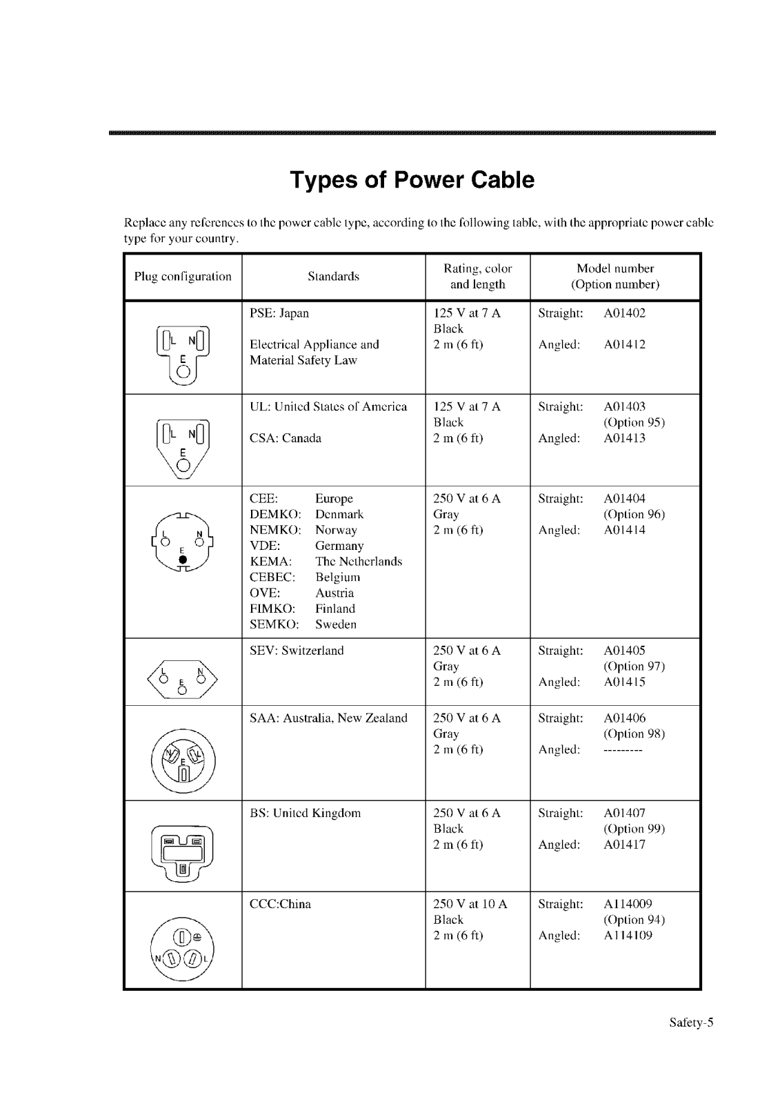
Types of Power Cable

Replace any references to the power cable type, according to the following table, with the appropriate power cable type for your country.

Plug configuration Standards Rating, color
and length
Model number
(Option number)
PSE: Japan
Electrical Appliance and
Material Safety Law
125 V at 7 A
Black
2 m (6 ft)
Straight: A01402
Angled: A01412
UL: United States of America
CSA: Canada
125 V at 7 A
Black
2 m (6 ft)
Straight: A01403
(Option 95)
Angled: A01413
CEE:EuropeDEMKO:DenmarkNEMKO:NorwayVDE:GermanyKEMA:The NetherlandsCEBEC:BelgiumOVE:AustriaFIMKO:FinlandSEMKO:Sweden 250 V at 6 A
Gray
2 m (6 ft)
Straight: A01404
(Option 96)
Angled: A01414
SEV: Switzerland 250 V at 6 A
Gray
2 m (6 ft)
Straight: A01405
(Option 97)
Angled: A01415
SAA: Australia, New Zealand 250 V at 6 A
Gray
2 m (6 ft)
Straight: A01406
(Option 98)
Angled:
BS: United Kingdom 250 V at 6 A
Black
2 m (6 ft)
Straight: A01407
(Option 99)
Angled: A01417
CCC:China 250 V at 10 A
Black
2 m (6 ft)
Straight: A114009
(Option 94)
Angled: A114109
Page 8

Page 9

Safety Summary (additional)

Servicing

  • Any adjustments or replacements must be performed by qualified personnel.
  • Capacitors inside the instrument may still be charged even when disconnected from their power source.
  • DIAGNOSTIC, ADJUSTMENT and REPLACEMENT described in this manual may be performed with power supplied to the instrument while protective covers are removed. Serious injury could occur if edges of the chassis unintentionally contacted.
Page 10

Page 11

PREFACE

Key notations in this manual Panel keys and soft keys are indicated in this manual as follows: Panel keys: In bold type Soft keys:In bold and italic type Example: MKR, MEAS Example: Normal Marker, Noise/Hz

Page 12

Page 13

TABLE OF CONTENTS

1 IN7 RODUCTION 1-1
1.1 Op erating Environment 1-1
1.1.1 Environmental Conditions 1-1
1.2 Ins truments Required 1-3
2 TH EORY OF OPERATION 2-1
2.1 Ov erview 2-1
2.2 Ba sic Theory 2-3
2.2.1 Source Block 2-3
2.2.2 Receiver Block 2-4
2.2.3 Front-end Block 2-5
2.2.4 Digital Block 2-6
2.2.5 Front Panel Block 2-7
3 PEI RFORMANCE TEST 3-1
3.1 Pre paration 3-1
3.2 Fre equency Accuracy and Range 3-2
3.2.1 Specifications 3-2
3.2.2 Instruments Required 3-2
3.2.3 Procedure 3-2
3.2.4 In Case of Failure 3-3
3.3 Ou tput Level Accuracy and Flatness 3-4
3.3.1 Specifications 3-4
3.3.2 Instruments Required 3-4
3.3.3 Procedure 3-4
3.3.4 In Case of Failure 3-5
3.4 Ou tout Level Linearity 3-6
3.4.1 Specifications 3-6
342 Instruments Required 3-6
343 Procedure 3-6
344 In Case of Failure 3-8
35 Di rectivity 3-9
351 Specifications 3-9
352 Instruments Required 3_9
353 Procedure 3_9
354 In Case of Failure 3-10
36 In ad Match Test 3-11
361 Load Match Test for the R3764/65/66/67AH 3_11
3.61 1 Specifications 3_11
3.6.1 2 Instruments Required 3_11
3.6.1 3 Procedure 3_11
2.0.1 2 11
Page 14
3.6.1.4 In Case of Failure 3-13
3.6.2 Load Match Test for the R3764/65/66/67BH 3-14
3.6.2.1 Specifications 3-14
3.6.2.2 Instruments Required 3-14
3.6.2.3 Procedure 3-14
3.6.2.4 In Case of Failure 3-15
3.6.3 Load Match Test for the R3764/65/66/67CH 3-16
3.6.3.1 Specifications 3-16
3.6.3.2 Instruments Required 3-16
3.6.3.3 Procedure 3-16
3.6.3.4 In Case of Failure 3-18
3.7 Noise Level 3-19
3.7.1 Noise Level for the R3764/65/66/67AH 3-19
3.7.1.1 Specifications 3-19
3.7.1.2 Instruments Required 3-19
3.7.1.2 Instations Required 3-19
3.7.1.4 In Case of Failure 3-19
3.7.2 Noise Level for the R3764/65/66/67BH 3-20
3.7.2 Noise Level for the R3704/05/06/07 DT 3-20
3.7.2.1 Specifications infinite and a second se 3-20
3.7.2.2 Installents Required 3-20
3.7.2.5 Theedure 3-20
3.7.3 Noise Level for the R3764/65/66/67CH 3-20
3.7.3 1 Specifications 3-21
3.7.3.2 Instruments Required 3_21
3.7.3.3 Procedure 3-21
3.7.3.4 In Case of Failure 3_21
3.8 Crosstalk 3-21
3.8.1 Crosstalk for the R3764/65/66/674H 3-22
3.8.1.1 Specifications 3-22
3.8.1.2 Instruments Required 3_22
3.8.1.3 Procedure 3_22
3.8.1.4 In Case of Failure 3-22
3.8.2 Crosstalk for the R3764/65/66/67BH 3-23
3.8.2 Crosstalk for the K5704/05/00/07BH 3-24
3.8.2.1 Specifications 3-24
3.8.2.2 Installents Required 3-24
3.8.2.4 In Case of Failure 3 25
3.8.2.4 III Case of Failure 3.26
3.8.3 Crosstalk for the K5704/05/00/07CH 3 26
3.8.3.7 Instruments Required 3-20
3 8 3 3 Procedure 3_26
3.8.3.4 In Case of Failure 3.07
2.0 Dynamic Level Accuracy 2 10
5.7 Dynamic Level Accuracy 5-20
Page 15
3.9.1 Dynamic Level Accuracy for the R3764/65/66/67AH 3-28
3.9.1.1 Specifications 3-28
3.9.1.2 Instruments Required 3-28
3.9.1.3 Procedure 3-29
3.9.1.3.1 A PORT Measurement for Dynamic Level Accuracy 3-29
3.9.1.3.2 B PORT Measurement for Dynamic Level Accuracy 3-31
3.9.1.4 In Case of Failure 3-32
3.9.2 Dynamic Level Accuracy for the R3764/65/66/67BH 3-33
3.9.2.1 Specifications 3-33
3.9.2.2 Instruments Required 3-33
3.9.2.3 Procedure 3-33
3.9.2.4 In Case of Failure 3-35
3.9.3 Dynamic Level Accuracy for the R3764/65/66/67CH 3-36
3.9.3.1 Specifications 3-36
3 9 3 2 Instruments Required 3-36
3 9 3 3 Procedure 3-36
39331 A PORT Measurement for Dynamic Level Accuracy 3-36
3.9.3.3.2 TEST PORT 1 Measurement for Dynamic Level Accuracy 3_38
3.9.3.4 In Case of Failure 3 40
3.10 Power Un Salf Test 3-41
3.10.1 Procedure 3 /1
3.10.2 In Case of Failure 3 /1
2 11 Dower Supply 2 41
5.11 Fower Supply 5-41
4 DIAGNOSTIC PROCEDURE 4-1
4.1 Instruments Required 4-1
4.2 Frequency Accuracy and Range 4-2
4.2.1 Instruments Required 4-2
4.2.2 Procedure 4-2
4.2.3 References 4-3
4.3 Output Level Accuracy, Flatness and Linearity 4-4
4.3.1 Instruments Required 4-4
4.3.2 Procedure 4-4
433 References 4-7
4.4 Unlock Failure 4-8
4.4.1 Instruments Required 4-8
4.4.2 Procedure 4-8
4 4 3 References 4-11
4.5 Directivity 4-12
4.5.1 Procedure 4 12
-+-12
A 12
T.J.2 NEIEIEIEES 4-12
4.6.1 Drogedure 4-13
1 12
4-13
Page 16

R3764/65/66/67H Series Maintenance Manual

4.6.2 References 4-13
4.7 Noise Level 4-14
4.7.1 Procedure 4-14
4.7.2 References 4-14
4.8 Crosstalk 4-15
4.8.1 Procedure 4-15
4.8.2 References 4-15
5 ADJUSTMENT AND CALIBRATION 5-1
5.1 Instruments Required 5-1
5.2 Frequency Error Adjustment 5-2
5.2.1 Instruments Required 5-2
5.2.2 Procedure 5-3
5.3 YTO Pre-tuning Adjustment 5-5
5.3.1 Instruments Required 5-5
5.3.2 Procedure 5-5
5.4 Source Adjustment 5-8
5.4.1 Instruments Required 5-8
5.4.2 Procedure 5-8
5.5 Input Adjustment 5-10
5.5.1 Input Adjustment for the R3764/65/66/67AH 5-10
5.5.1.1 Instruments Required 5-10
5.5.1.2 Procedure 5-11
5.5.2 Input Adjustment for the R3764/65/66/67BH 5-13
5.5.2.1 Instruments Required 5-13
5.5.2.2 Procedure 5-13
5.5.3 Input Adjustment for the R3764/65/66/67CH 5-15
5.5.3.1 Instruments Required 5-15
5.5.3.2 Procedure 5-15
6 REPLACEMENT PROCEDURE 6-1
6.1 The Tools 6-1
6.2 Procedure 6-2
6.2.1 Disassembling the Cover 6-2
6.2.2 Disassembling the Front Panel 6-3
6.2.3 Replacing Modules of the Source and Receiver Blocks 6-5
6.2.3.1 Replacing the M10 Source Module 6-5
6.2.3.2 Replacing the Input Modules 6-6
6.2.3.2.1 Replacing the M01 Input Module 6-6
6.2.3.2.2 Replacing the M02 Input Module 6-6
6.2.3.2.3 Replacing the M03 Input Module 6-7
6.2.3.3 Replacing the M12 Coupler Module 6-8
6.2.3.4 Replacing the Bridge Module 6-9
Page 17

R3764/65/66/67H Series Maintenance Manual

6.2.3.4.1 Replacing the M06 Bridge Module 6-9
6.2.3.4.2 Replacing the M07 Bridge Module
6 5.2.3.5 Replacing the M13 SW Module 6-10
6 5.2.3.6 Replacing the M09 YTO Module 6-11
6 5.2.3.7 Replacing the M14 4.44 GHz DRO Module 6-12
6 5.2.3.8 Replacing the M04 PG Module 6-13
6.2 2.4 Replacing the Power Supply 6-14
6.2 2.5 Replacing the Digital Block 6-15
6.2 2.6 Replacing the M05 Synthesizer Module 6-16
6.2 2.7 Replacing the M08 PLL Module 6-17
7 PREVENTIVE MAINTENANCE 7-1
7.1 Procedure 7-1
7.1 .1 Cleaning LCD Filter 7-1
7.1 .2 Checking the Fan 7-1
7.1 .3 Checking the Front Connectors 7-1
7.1.4 Cleaning the Floppy Disk Drive Head
APP PENDIX A-1
A.1 Flowchart A-1
A.2 Performance Test Report A-13
A.3 Parts List A-20
A.4 Ordering Information A-21
A.5 Figures A-22
Page 18

Page 19

LIST OF ILLUSTRATIONS

No. Title Page
1-1 Operating Environment 1-2
2-1 Simplified Block Diagram 2-2
2-2 Source Block Diagram 2-3
2-3 Receiver Block 2-4
2-4 Front-end Block Diagram 2-5
2-5 Digital Block Diagram 2-6
2-6 Front Panel Block Diagram 2-7
3-1 Frequency Accuracy and Range 3-2
3-2 Output Level Accuracy and Flatness 3-4
3-3 Output Level Linearity 3-6
3-4 Directivity 3-9
3-5 Load Match Test of A PORT 3-11
3-6 Load Match test of B PORT 3-13
3-7 Load Match Test of TEST PORT 2 3-14
3-8 Load Match Test of TEST PORT 1 3-16
3-9 Load Match Test of TEST PORT 2 3-18
3-10 Crosstalk for the R3764/65/66/67AH 3-22
3-11 Crosstalk for the R3764/65/66/67BH 3-24
3-12 Crosstalk for the R3764/65/66/67CH 3-26
3-13 Connections between A PORT and SOURCE 3-29
3-14 Connection between B PORT and SOURCE 3-31
3-15 Connection between TEST PORT 1 and TEST PORT 2 for R3764/65/66/67BH 3-33
3-16 Connections between TEST PORT 1 and TEST PORT 2 for the testing TEST PORT 2 3-36
3-17 Connections between TEST PORT 1 and TEST PORT 2 for the testing TEST PORT 1 3-38
4-1 Frequency Accuracy and Range 4-2
4-2 Lock vs. Unlock 4-3
4-3 Unlock Failure 4-8
4-4 Trace of the Output at J2 4-10
5-1 Connection for the Frequency Accuracy 5-3
5-2 YTO Pre-tuning 5-5
5-3 Position of the R112 and R116 5-6
5-4 Connection of the Source Adjustment 5-8
5-5 Input Adjustment 5-11
5-6 Connection for Input Adjustment 5-13
5-7 Input Adjustment of R3764/65/66/67CH 5-15
6-1 Cover Disassembly 6-2
6-2 Disassembling the Front Panel 6-3
6-3 Disassembling the LCD and Key-pad Modules 6-4
6-4 Replacing the Source Module 6-5
6-5 Replacing the M01 Input Module 6-6
6-6 Replacing the M02 Input Modules 6-6
Page 20

List of Illustrations

No. D. Title
6-7 Replacing the M03 Input Module 6-7
6-8 Replacing the Coupler Module 6-8
6-9 Replacing the Bridge Module 6-9
6-10 Replacing the Bridge Module 6-9
6-11 Replacing the SW Module 6-10
6-12 Replacing the YTO Module 6-11
6-13 Replacing the DRO Module 6-12
6-14 Replacing the PG Module 6-13
6-15 Replacing the Power Supply 6-14
6-16 Replacing the Digital Block 6-15
6-17 Replacing the Synthesizer Module 6-16
6-18 Replacing the PLL Module 6-17
A-1 R3764/65/66/67AH : Connector Number Jx and Px A-22
A-2 R3764/65/66/67BH : Connector Number Jx and Px A-23
A-3 R3764/65/66/67CH : Connector Number Jx and Px A-24
Page 21

LIST OF TABLES

No. Title Page
1-1 Instruments Required 1-3
2-1 Frequency Range and Levels 2-1
3-1 Instruments Required 3-1
3-2 Check Point for the Frequency Accuracy 3-3
3-3 Check Point for the Output Level Accuracy 3-5
3-4 Output Level Linearity 3-8
3-5 Check Point for the Directivity 3-10
3-6 Check Point for the Load Match Test for the R3764/65/66/67AH 3-12
3-7 Check Point for the Load Match Test for the R3764/65/66/67BH 3-15
3-8 Check Point for the Load Match Test for the R3764/65/66/67CH 3-17
3-9 Check Point for the Ccrosstalk for the R3764/65/66/67AH 3-23
3-10 Check Point for the Crosstalk for the R3764/65/66/67BH 3-25
3-11 Check Point for the Crosstalk for the R3764/65/66/67CH 3-27
3-12 Check Point for the R3764/65/66/67AH 3-30
3-13 Check Point for the R3764/65/66/67BH 3-34
3-14 Check Point for the R3764/65/66/67CH 3-37
4-1
5-1
Instruments Required 4-1
5-1
5-1 5-1
A-1 Frequency Accuracy and Range A-13
A-2 Output Level Accuracy and Flatness A-13
A-3 Output Level Linearity (for R3764/65/66/67AH) A-13
A-4 Output Level Linearity (for R3764/65/66/67BH) A-14
A-5 Output Level Linearity (for R3764/65/66/67CH) A-14
A-6 Directivity A-15
A-7 Load Match Test of R3764/65/66/67AH A-15
A-8 Load Match Test of R3764/65/66/67BH A-15
A-9 Load Match Test of R3764/65/66/67CH A-15
A-10 Noise Level of R3764/65/66/67AH A-15
A-11 Noise Level of R3764/65/66/67BH A-15
A-12 Noise Level of R3764/65/66/67CH A-15
A-13 Crosstalk of R3764/65/66/67AH A-16
A-14 Crosstalk of R3764/65/66/67BH A-16
A-15 Crosstalk of R3764/65/66/67CH A-16
A-16 Dynamic Level Accuracy A PORT (for R3764/65/66/67AH) A-17
A-17 Dynamic Level Accuracy B PORT (for R3764/65/66/67AH) A-17
A-18 Dynamic Level Accuracy (for R3764/65/66/67BH) A-18
A-19 Dynamic Level Accuracy TEST PORT 1 (for R3764/65/66/67CH)) A-18
A-20 Dynamic Level Accuracy TEST PORT 2 (for R3764/65/66/67CH)) A-19
Page 22

Page 23

1.1 Operating Environment

1 INTRODUCTION

This maintenance manual is a complete service guide for the R3764AH/BH/CH, R3765AH/BH/CH R3766AH/BH/CH or R3767AH/BH/CH network analyzers. This manual contains information on basic theory, performance tests, diagnostic tests, adjustments and calibrations for these network analyzers.

1.1 Operating Environment

This section describes the environmental conditions and power requirements necessary to use the spectrum analyzer.

1.1.1 Environmental Conditions

These network analyzers should be installed in an area which satisfies the following conditions:

  • Ambient temperature: 0°C to +50°C (32°F to 122°F) (operating temperature)
  • Relative humidity: 85% or less (without condensation)
  • An area free from corrosive gas
  • An area away from direct sunlight
  • A dust-free area
  • An area free from vibrations
  • A low noise area

Although these network analyzers have been designed to withstand a certain amount of noise riding on the AC power line, it should be used in an area of low noise. Use a noise cut filter when ambient noise is unavoidable.

• An area allowing unobstructed air flow

These network analyzers have an exhaust cooling fan on the rear panel and an exhaust vent on the bottom side toward the front. Never block these areas as the resulting internal temperature rise will affect measurement accuracy.

Page 24

1.1 Operating Environment

Figure 1-1 Operating Environment

These network analyzers can be used safely under the following conditions:

  • Altitude: 2000m maximum above the sea level
  • Installation category II
  • Pollution degree 2
Page 25

1.2 Instruments Required

1.2 Instruments Required

The following are the instruments used by this maintenance manual.

Test item Instrument Recommended model Remarks
32 Frequency Accuracy and Range Frequency R5372* up to 8 GHz with 7 digit
2.2 requerey recoursey and range Counter 10072 display
RF Cable Λ01273* N(m)/N(m) 50Ω
3.3 Output Level Accuracy and Flatness Power meter HP436A/HP437B/HP438A***
Power sensor HP8482A*** up to 4 GHz
3.4 Output Level Linearity Power meter НР436Л/НР437В/НР438Л***
Power sensor HP8482A*** up to 4 GHz
3.5 Directivity Calibration kit Model 9617A3* up to 4 GHz
- N-type connector
RF Cable A01273* N(m)/N(m) 50Ω
3.6 Load Match Test Calibration kit Model 9617A3* up to 4 GHz
N-type connector
Directivity bridge ZRB2VAR-52** up to 4 GHz
N-type connector
RF Cable(Qty=3) A01273* N(m)/N(m) 50Ω
3.7 Noise Level None
3.8 Crosstalk Calibration kit Model 9617A3* up to 4GHz
DE coblo 4.01272* N-type connector
2.0 Durane I mul A communi RI cable A01273* N(m)/N(m) 5042
5.9 Dynamic Level Accuracy Step attenuator протов Accuracy within 0.02dB
RE cable A01253-060 SMA(m)/SMA(m) 500
Qty=2
Adopter HRM-554S N(m)/SMA(f) Qty=2
3-dB attenuators AT-103 SMA(f)/SMA(m) Qty=2
4.2 Frequency Accuracy and Range Spectrum Ana- R3265* up to 8 GHz with counter
lyzer mode
4.3 Output Level Accuracy, Flatness RF cable A01002* SMA(m)/SMA(m) 50Ω
and Linearity RF cable Λ01273* N(m)/N(m) 50Ω
4.4 Unlock Failure Adopters HRM-501S SMA(f)/SMA(f)
5.2 Frequency Error Adjustment Spectrum Ana- R3265* up to 8 GHz with counter
lyzer mode
RF Cable A01273* N(m)/N(m) 50Ω
Program Floppy Dis ;k
5.3 YTO Pre-tuning Adjustment Spectrum Ana- R3265* up to 8 GHz with counter
5.4 Summer A disastrument lyzer mode
5.4 Source Aujustment RF Cable A01273* N(m)/N(m) 50Ω
5.5 Input Adjustment Power meter HP437B*** 4
Power sensor HP8481A*** 4
Program Floppy Dis sk
I
4
GPIB Cable 408JE-104*
Table 1-1 Instruments Required

NOTE: * is manufactured by ADVANTEST.

** is manufactured by ROHDE&SCWARZ.

*** is manufactured by HEWLETT PACKARD.

Page 26

Page 27

2.1 Overview

2 THEORY OF OPERATION

This chapter describes the basic operation of these network analyzers using block diagrams and flowcharts. These diagrams are not intended to provide information at a component level.

2.1 Overview

These network analyzer have the following frequency and level range. When Option 10 is installed, The output signal can be adjust between 0 dB and 70 dB.

The R3766AH/BH/CH and R3767BH/CH have the range of 3.8 GHz to 8.0 GHz added. A fixed value is set as its level within a range of 3.8 GHz to 8.0 GHz for the R3766AH/BH/CH and R3767AH/BH/CH. The Frequency and Level ranges are shown in below.

Types 40 MHz to 3.8 GHz 3.8 GHz to 8.0 GHz
R3764/65AH +17 dBm to -8 dBm N/A
BH +7 dBm to -18 dBm N/A
CH +10 dBm to -15 dBm N/A
R3766/67AH +17 dBm to -8 dBm A fixed value / over -3 dBm
BH +7 dBm to -18 dBm A fixed value / over +6 dBm
CH +10 dBm to -15 dBm A fixed value / over -13 dBm

Table 2-1 Frequency Range and Levels

Page 28

2.1 Overview

The network analyzer consists of five blocks:

  • 1. Source Block
  • 2. Receiver Block
  • 3. Front-end Block
  • 4. Front Panel Block
  • 5. Digital Block

See Figure 2-1 below.

Figure 2-1 Simplified Block Diagram

Page 29

2.2 Basic Theory

The source block generates the synthesized RF signal. The generated signal is supplied to a DUT through the front-end block to measure the forward/reverse characteristics. After the signal has passed the DUT, the signal returns to the receiver block through the Front end block. In the receiver block, the signal is converted to a low frequency and passes to the digital block. The passed signal is converted to the digital signal by the A/D converter in the digital block. The digital signal is calculated to obtain the amplitude, phase characteristics and the group delay time, forward/reverse characteristics. The result are displayed on the front panel block.

2.2.1 Source Block

The source block consists of the synthesizer, PLL, source, 4.44 GHz DRO, YTO, coupler modules.

The synthesized source module provides an RF signal which is generated by mixing the 4.44 GHz DRO module with the 4.4 GHz to 8.2 GHz YTO module.

For the R3766AH/BH/CH or R3767AH/BH/CH an additional frequency range of 3.8 GHz to 8.0 GHz is available, using the synthesized YTO module.

Figure 2-2 Source Block Diagram

Page 30

2.2.2 Receiver Block

The receiver block consists of three input modules and one PG module. The input modules are referred to as Ach, Bch and Rch. The Rch input module is connected to the coupler module internally. The other two INPUT modules, Ach and Bch, are connected to the Front-end block.

The 820 kHz signal is generated by sampling the applied signal through a DUT and the signal from the PG module. The 820 kHz signal is referred to as 1st-IF.

Then the 20 kHz signal, which is referred to as the 2nd-IF, is generated by mixing the 1st-IF with the signal from the synthesizer module (in the source block). 2nd-IF is then sent to the A/D converter for further analysis.

Figure 2-3 Receiver Block

Page 31

2.2.3 Front-end Block

The front-end block consists of the bridge and SW modules. The number of the bridge module depends on the types.

R3764/65/66/67AH

These network analyzers have SOURCE, A PORT and B PORT connectors. The SOURCE connector is directly connected to the source block. The A PORT and B PORT are directly connected to the Ach and Bch input modules in the receiver block.

R3764/65/66/67BH

These network analyzers have TEST PORT 1 and TEST PORT 2 connectors. The TEST PORT 1 connector is connected to the source block through the bridge module to measure the reverse characteristics by connecting to the Ach input module. The TEST PORT 2 is directly connected to the Bch input module.

R3764/65/66/67CH

These network analyzer have TEST PORT 1 and TEST PORT 2 connectors. The TEST PORT 1 is connected to the source block through the bridge and SW modules. The SW module switches the generated signal to supply the signals to DUT. Also The bridge modules are connected between the each ports and the SW module. The connected bridge module to TEST PORT 2 measures the reverse characteristics by the Bch input. See Figure 2-4.

Figure 2-4 Front-end Block Diagram

Page 32

2.2.4 Digital Block

The digital block consists of the A/D converter and CPU modules. The CPU module consists of the 32-bit high performance CPU, a special CPU, DSP and so on.

The digital block controls the source, receiver, front-end and the front panel blocks. They provide mathprocessing functions, as well as communications between the analyzer and the external controller. Data processing from the A/D converter is performed by the DSP and 32-bit high performance CPU and the internal Basic program can be run from this CPU. For the convenience of Basic programmers, an external IBM PC/AT keyboard and VGA monitor can be connected. The front panel block is controlled by the special CPU. See Figure 2-5.

Figure 2-5 Digital Block Diagram

Page 33

2.2.5 Front Panel Block

The front panel block consists of the key-pad and display modules. The key-pad module contains the encoder for convenience to move a marker. For the R3765AH/BH/CH or R3767AH/BH/CH the display module uses the 7.8-inch color TFT LCD module. For the R3764AH/BH/CH or R3766AH/BH/CH the display module uses the VGD module.

The display and the key-pad modules are controlled by the digital block for the user. See Figure 2-6.

Figure 2-6 Front Panel Block Diagram

Page 34

Page 35

3.1 Preparation

3 PERFORMANCE TEST

This chapter describes how to test the network analyzer. If any error occurs, perform Chapter 4, "DIAGNOS-TIC PROCEDURE."

Make sure that the testing instrument used meets its own published specifications and that all connectors are clean, before starting tests. All connectors should be firmly connected.

For your convenience, you can use the performance test report in Section A.2.

3.1 Preparation

The network analyzer to be tested should be warmed up for at least 30 minutes before starting tests. Any additional instrument used for performance tests should also be warmed up as appropriate.

The following instruments are required for each test item in the table.

Test item Instrument Recommended model Remarks
3.3 Frequency
Accuracy and
Frequency Counter R5372* up to 8 GHz with 7 digit dis-
play
Range RF Cable A01273* N(m)/N(m) :50Ω
3.4 Output Level Power meter HP436A/HP437B/HP438A**
Accuracy and
Flatness
Power sensor HP8482A** up to 4 GHz
3.5 Output Level Power meter HP436A/HP437B/HP438A**
Linearity Power sensor HP8482A** up to 4 GHz
3.6 Directivity Calibration Kit Model 9617A3* up to 4 GHz
N-type connectors
RF Cable A01273* N(m)/N(m) :50Ω
3.7 Load Match
Test
Calibration Kit Model 9617A3* up to 4 GHz
N-type connectors
Directivity Bridge ZRB2VAR-52* up to 4 GHz
N-type connectors
RF Cable (Qty=3) A01273* N(m)/N(m) :50Ω
3.8 Noise Level None
3.9 Crosstalk Calibration Kit Model 9617A3* up to 4 GHz
N-type connectors
RF Cable A01273* N(m)/N(m) :50Ω
Table 3-1 Instruments Required
Tuble 0 1 THOSE CHICKING nequireu

NOTE: * is manufactured by ADVANTEST.

** is manufactured by HEWLETT PACKARD.

Page 36

3.2 Frequency Accuracy and Range

3.2 Frequency Accuracy and Range

This test measures the frequency accuracy and range of the network analyzer. This part of the performance test checks the PLL for the correct operation. This check is the most important. The frequency range depends on type.

3.2.1 Specifications

Frequency accuracy: 20 ppm or less

Range:

40 MHz to 3.8 GHz 3.8 GHz to 8.0 GHz for the R3766AH/BH/CH or R3767AH/BH/CH only

3.2.2 Instruments Required

  • Frequency counter Recommended model R5372
  • RF Cable Recommended model A01273 (N(m)/N(m) 50Ω)

3.2.3 Procedure

  • Performing the Frequency Accuracy
    • (1) Connect the Frequency counter to the network analyzer using the RF cable connected to the Frequency counter as shown in Figure 3-1.

Figure 3-1 Frequency Accuracy and Range

NOTE: Figure 3-1 shows the connection the R3764/65/66/67AII and the Frequency counter. For the R3764/65/66/67BII or R3764/65/66/67CII the RF cable is connected to TEST PORT 1, in place of SOURCE.

Page 37

3.2 Frequency Accuracy and Range

  • (2) Press PRESET to initialize the network analyzer.
  • (3) Press SPAN , 0 and x1 to set the span to zero.
  • (4) Press MENU, TRIGGER , and HOLD to stop the sweep.

• Performing the Frequency Range

  • (5) Press CENTER , 4 , 0 and MHz to set the center frequency to 40 MHz.
  • (6) Record the counter reading on the performance test report.
  • (7) Repeat steps (5) and (6) for each frequency setting listed on Table 3-2.
Table 3-2 Check Point for the Frequency Accuracy
Setting Specification
40 MHz ≤20ppm
50 MHz
2.0 GHz
3.8 GHz
6.0 GHz (for R3766AH/BH/CH or R3767AH/BH/CH only)
8.0 GHz (for R3766AH/BH/CH or R3767AH/BH/CH only)
3.2.4 In Case of Failure

Perform Section 5.2, "Frequency Error Adjustment."

Page 38

3.3 Output Level Accuracy and Flatness

3.3 Output Level Accuracy and Flatness

This section describes how to measure the RF output power level accuracy at 50 MHz and, the output level flatness reference on 0 dBm at 50 MHz.

3.3.1 Specifications

Accuracy:± 0.5 dBm at 50 MHzFlatness:± 2.0 dB over the frequency range

3.3.2 Instruments Required

Power meter and sensor

Recommended model: HP437B (HP438A) HP8482A

(Frequency range: up to 3.8 GHz, Level range: -15 dBm to +17 dBm)

3.3.3 Procedure

  • Performing the output level accuracy
    • (1) Calibrate the power meter with the sensor.
    • (2) Connect the sensor to the network analyzer as shown in Figure 3-2.

Figure 3-2 Output Level Accuracy and Flatness

NOTE: Figure 3-2 shows the connection the R3764/65/66/67AH and the Sensor. For the R3764/65/66/ 67BH or R3764/65/66/67CH, the Sensor is connected to TEST PORT 1, in place of SOURCE as shown in Figure 3-2.

Page 39

3.3 Output Level Accuracy and Flatness

  • (3) Press PRESET to initialize the network analyzer.
  • (4) Press CENTER , 5 , 0 and MHz to set the center frequency to 50 MHz.
  • (5) Press SPAN , 0 and x1 to set the span to zero.
  • (6) Press MENU, TRIGGER and HOLD to stop the sweep.
  • (7) Press MENU, MENU, POWER , 0 and x1 to set the output level to 0 dBm.
  • (8) Record the power meter level indicated by the power meter on the performance test report.

• Performing the Output Level Flatness

  • (9) Set the calibration factor of the power sensor for each frequency to the power meter.
  • (10) Press CENTER , 4 , 0 and MHz to set the center frequency to 40 MHz.
  • (11) Record the level of the power meter on the performance test report.
  • (12) Repeat steps (10) to (12) for each frequency setting listed on Table 3-3.

Table 3-3 Check Point for the Output Level Accuracy

Setting Specification
40 MHz ±2.0 dB
50 MHz ±0.5 dBm
100 MHz ±2.0 dB
500 MHz
1.5 GHz
2.0 GHz
3.0 GHz
3.8 GHz

(13) For each frequency, calculate the difference between the reference level and each level on the performance test report.

3.3.4 In Case of Failure

Perform Section 4.3, "Output Level Accuracy, Flatness and Linearity."

Page 40

3.4 Output Level Linearity

3.4 Output Level Linearity

This section describes how to measure the output level linearity. The output level linearity is based on 50 MHz.

3.4.1 Specifications

R3764/65/66/67AH: (Reference level: +7 dBm at 50 MHz)

±0.4 dB: +12 dBm to -3 dBm

±0.7 dB: +17 dBm to -8 dBm

R3764/65/66/67BH: (Reference level: -3 dBm at 50 MHz)

±0.4 dB: +2 dBm to -13 dBm

±0.7 dB: +7 dBm to -18 dBm

R3764/65/66/67CH: (Reference level: 0 dBm at 50 MHz)

±0.4 dB: +5 dBm to -10 dBm

±0.7 dB: +10 dBm to -15 dBm

3.4.2 Instruments Required

Power meter and sensor

Recommended model: HP437B or HP438A HP8482A

(Frequency range: up to 3.8 GHz, Level range: -15 dBm to +17 dBm: calibration tolerance less than 0.5 dB)

3.4.3 Procedure

  • Perform the output level linearity
    • (1) Calibrate the power meter with the sensor.

Connect the sensor to the network analyzer as shown in Figure 3-3.

Figure 3-3 Output Level Linearity

Page 41

3.4 Output Level Linearity

NOTE: Figure 3-3 Shows the R3764/65/66/67AII connected to the sensor. For the R3764/65/66/67BII or R3764/65/66/67CH, the sensor is connected to TEST PORT 1, in place of SOURCE.

  • (2) Press PRESET to initialize the network analyzer.
  • (3) Press CENTER , 5 , 0 and MHz to set the center frequency to 50 MHz.
  • (4) Press SPAN , 0 and x1 to set the span to zero.
  • (5) Press MENU, TRIGGER and HOLD to stop the sweep.
  • (6) Set the power level depends on types.
    • R3764/65/66/67AH: Press MENU, MENU, POWER , 7 and x1 to set the output level to +7 dBm.
    • R3764/65/66/67BH: Press MENU, MENU, POWER , -, 3 and x1 to set the output level to -3 dBm.
    • R3764/65/66/67CH: Press MENU, MENU, POWER , 0 and x1 to set the output level to 0 dBm.
  • (7) Press REL to set ratio test mode.
  • (8) Press 0 and x1 to set a level to 0 dB.
  • (9) Read the Power meter level indicated by the power meter for the reference level value.
  • (10) Record the level of the power meter on the performance test report.
  • (11) Repeat steps (9) to (10) for each setting level listed on Table 3-4.
Page 42

3.4 Output Level Linearity

(For R376 64/65/66/67AH) (For R376 4/65/66/67BH) (For R37 6 4/65/66/67CH)
Setting Specification Setting Specification רו ו Setting Specification
-8 dBm ±0.7 dB -18 dBm ±0.7 dB -1. 5 dBm ±0.7 dB
-7 dBm -17 dBm -1 4 dBm
-6 dBm -16 dBm -1 3 dBm
-5 dBm -15 dBm -1 2 dBm
-4 dBm -14 dBm -1 1 dBm
-3 dBm ±0.4 dB -13 dBm ±0.4 dB -1 0 dBm ±0.4 dB
-2 dBm -12 dBm -9 dBm
-1 dBm -11 dBm -8 dBm
0 dBm -10 dBm -7 dBm
+1 dBm -9 dBm -6 dBm
+2 dBm -8 dBm -5 dBm
+3 dBm -7 dBm -4 dBm
+4 dBm -6 dBm -3 dBm
+5 dBm -5 dBm -2 dBm
+6 dBm -4 dBm -1 dBm
+7 dBm Reference point -3 dBm Reference point 0 dBm Reference point
+8 dBm ±0.4 dB -2 dBm ±0.4 dB + 1 dBm ±0.4 dB
+9 dBm -1 dBm +2 dBm
+10 dBm 0 dBm +3 3 dBm
+11 dBm +1 dBm +4 l dBm
+12 dBm +2 dBm +5 i dBm
+13 dBm ±0.7 dB +3 dBm ±0.7 dB +6 o dBm ±0.7 dB
+14 dBm +4 dBm +7 / dBm
+15 dBm +5 dBm +8 ∛ dBm
+16dBm +6dBm +9 ) dBm
+17dBm +7dBm +1 0 dBm

Table 3-4 Output Level Linearity

(12) For each frequency level, calculate the linearity error using the following formula:

(Linearity Error) = (Measured Value) - (Set Value) - (Offset value)

NOTE: The offset value is a power meter error at the reference point.

3.4.4 In Case of Failure

Perform Section 4.3, "Output Level Accuracy, Flatness and Linearity."

Page 43

3.5 Directivity

3.5 Directivity

This section describes how to test the directivity. This section applies to the R3764/65/66/67BH or R3764/65/66/67CH.

3.5.1 Specifications

-30 dB or less, 40 MHz to 2.6 GHz

-26 dB or less, 2.6 GHz to 3.8 GHz

-22 dB or less, 3.8 GHz to 8.0 GHz (for the R3766BH/CH or R3767BH/67CH only)

3.5.2 Instruments Required

Calibration kit

Recommended model: 9617A3 (Frequency response: up to 8 GHz)

3.5.3 Procedure

  • Performing the Normalize function (SHORT) of TEST PORT 1
    • (1) R3764/65/66/67AH:

Press MEAS and REFLECTION to prepare the normalize function for TEST PORT 1.

R3764/65/66/67BH or R3764/65/66/67CH: Press MEAS and S11 REFL REV to prepare the normalize function for TEST PORT 1.

(2) Connect a short standard to TEST PORT 1 as shown in Figure 3-4.

Figure 3-4 Directivity

  • (3) Press CAL and NORMALIZE (SHORT) to perform the normalization.
  • (4) Remove the short standard.
  • Testing the directivity
    • (5) Connect a load standard to TEST PORT 1.
Page 44
3.5 Directivity

  • (6) Press MKR to display the marker on the screen.
  • (7) Read the highest value on the trace within a range of 40 MHz to 2.6 GHz by turning the encoder knob to move the marker.
  • (8) Record the marker value on the performance test report.
  • (9) Repeat step (7) for each frequency range listed on Table 3-5.
Table 3-5 Check Point for the D irectivity
Setting Specification
-2.6 GHz (for R3764/65BH, R3764/65CH) ≤-30 dB
-3.8 GHz ≤-26 dB
-8.0 GHz (for R3766/67BH, R3766/67CH) ≤-22 dB

NOTE: For the R3764/65/66/67CH, perform the following steps (10) through (17) shown below.

  • Perform the Normalize function (SHORT) of TEST PORT 2
    • (10) Press MEAS and S22 REFL REV to prepare the normalize function on TEST PORT 2.
    • (11) Remove the load standard from TEST PORT 1.
    • (12) Connect the short standard to TEST PORT 2.
    • (13) Press CAL and NORMALIZE (SHORT) to perform the calibration and normalization.
    • (14) Remove the short standard.
  • Testing the directivity
    • (15) Connect the load standard to TEST PORT 2.
    • (16) Press MKR to display the marker on the screen.
    • (17) Read the highest value on the trace within a range of 40 MHz to 2.6 GHz by turning the encoder knob to move the marker.
    • (18) Record the marker value on the performance test report.
    • (19) Repeat step (17) for each frequency range listed on the Table 3-5.

3.5.4 In Case of Failure

Perform Section 4.5, "Directivity"

Page 45

3.6 Load Match Test

3.6.1 Load Match Test for the R3764/65/66/67AH

This section describes how to test load matching between SOURCE and A PORT or B PORT. This section applies only to the R3764/65/66/67AH.

3.6.1.1 Specifications

  • -18 dB or less, 40 MHz to 2.6 GHz
  • -16 dB or less, 2.6 GHz to 3.8 GHz

-14 dB or less, 3.8 GHz to 8.0 GHz (for the R3766/67AH, R3766/67BH or R3766/67CH only)

3.6.1.2 Instruments Required

  • Calibration kit Recommended model: 9617A3 (Frequency response: up to 8 GHz)
  • Directivity bridge Recommended model: ZRV2VAR-52
  • RF cable Recommended model A01273 (N(m)/N(m) 50Ω)

3.6.1.3 Procedure

  • Performing the 1 PORT FULL Calibration of A PORT
    • (1) Connect the directivity bridge to the network analyzer by three RF cables as shown in Figure 3-5.

Figure 3-5 Load Match Test of A PORT

  • (2) Press MEAS and B/R to perform 1 port full calibration.
  • (3) Press CAL, CAL MENUS and 1 PORT FULL CAL.
  • (4) Connect an open standard to the RF cable and press OPEN .
Page 46

  • (5) Remove the open standard.
  • (6) Connect a short standard to the RF cable and press SHORT .
  • (7) Remove the short standard.
  • (8) Connect a load standard to the RF cable and press LOAD .
  • (9) Press DONE 1 PORT.
  • (10) Remove the load standard.
  • Performing the Load Match Test of A PORT
    • (11) Connect the RF cable to A PORT on the network analyzer.
    • (12) Press MKR to display the marker on the screen.
    • (13) Read the highest value on the trace within a range of 40 MHz to 2.6 GHz by turning the encoder knob to move the marker.
    • (14) Record the marker value on the performance test report.
    • (15) Repeat steps (13) and (14) for each frequency range listed on Table 3-6.
Table 3-6 Check Point for the Load Match Test for the R3764/65/66/67AH
Setting Specification
A PORT 40 MHz to 2.6 GHz ≤-30 dB
2.6 GHz to 3.8 GHz ≤-26 dB
3.8 GHz to 8.0GHz (for R3766AH or R3767AH only) ≤-22 dB
B PORT 40 MHz to 2.6 GHz ≤-30 dB
2.6 GHz to 3.8 GHz ≤-26 dB
3.8 GHz to 8.0 GHz (for R3766AH or R3767AH only) ≤-22 dB

  • (16) Remove the RF cable from B PORT.
  • Performing the 1 PORT FULL Calibration of B PORT
    • (17) Connect the RF cable to A PORT as shown in Figure 3-6.
Page 47

R3764/65/66/67H Series Maintenance Manual

3.6 Load Match Test

Figure 3-6 Load Match test of B PORT

  • (18) Press MEAS and A/R to perform 1 port full calibration.
  • (19) Press CAL, CAL MENUS and I PORT FULL CAL again.
  • (20) Connect the open standard to the RF cable and press OPEN .
  • (21) Remove the open standard.
  • (22) Connect the short standard to the RF cable and press SHORT .
  • (23) Remove the short standard.
  • (24) Connect the load standard to the RF cable and press LOAD .
  • (25) Press DONE 1 PORT.
  • (26) Remove the load standard.
  • Performing the Load Match Test of B PORT
    • (27) Connect the RF cable to B PORT on the network analyzer.
    • (28) Press MKR to display the marker on the screen.
    • (29) Read the highest value on the trace within a range of 40 MHz to 2.6 GHz by turning the encoder knob to move the marker.
    • (30) Record the marker value on the performance test report.
    • (31) Repeat step (29) for each frequency range listed on Table 3-6.

3.6.1.4 In Case of Failure

Perform Section 4.6, "Load Match Test."

Page 48

3.6.2 Load Match Test for the R3764/65/66/67BH

This section describes how to test load Matching between TEST PORT 1 and TEST PORT 2. This section applies only to the R3764/65/66/67BH.

3.6.2.1 Specifications

  • -18 dB or less, 40 MHz to 2.6 GHz
  • -16 dB or less, 2.6 GHz to 3.8 GHz
  • -14 dB or less, 3.8 GHz to 8.0 GHz (For the R3766/67BH only)
3.6.2.2 Instruments Required

  • Calibration kit Recommended model: 9617A3 (Frequency response: up to 8 GHz)
  • RF Cable Recommended model A01273 (N(m)/N(m) 50Ω)

3.6.2.3 Procedure

  • Performing the 1 PORT FULL Calibration of PORT 2
    • (1) Connect the RF cable to the network analyzer as shown in Figure 3-7.

Figure 3-7 Load Match Test of TEST PORT 2

  • (2) Press MEAS and REFLECTION to perform 1 port full calibration.
  • (3) Press CAL, CAL MENUS and 1 PORT FULL CAL.
  • (4) Connect an open standard to the RF cable and press OPEN .
  • (5) Remove the open standard.
  • (6) Connect a short standard to the RF cable and press SHORT .
Page 49

  • (7) Remove the short standard.
  • (8) Connect a load standard to the RF cable and press LOAD .
  • (9) Press DONE 1 PORT.
  • (10) Remove the load standard.

• Performing the Load Match Test of TEST PORT 2

  • (11) Connect the RF cable to TEST PORT 2 on the network analyzer.
  • (12) Press MKR to display the marker on the screen.
  • (13) Read the highest value on the trace within a range of 40 MHz to 2.6 GHz by turning the encoder knob to move the marker.
  • (14) Record the marker value on the performance test report.
  • (15) Repeat step (13) for each frequency range listed on Table 3-7.

Table 3-7 Check Point for the Load Match Test for the R3764/65/66/67BH

Setting Specification
40 MHz to 2.6 GHz ≤-18 dB
2.6 GHz to 3.8 GHz ≤-16 dB
3.8 GHz to 8.0 GHz (for R3766/67BH only) ≤-14 dB
3.6.2.4 In Case of Failure

Perform Section 4.6, "Load Match Test."

Page 50

3.6.3 Load Match Test for the R3764/65/66/67CH

This section shows how to check load Matching between TEST PORT 1 and TEST PORT 2. This section applies only to the R3764/65/66/67CH. Make sure to clean all connectors in the calibration kit and the RF cable.

3.6.3.1 Specifications

  • -18 dB or less, 40 MHz to 2.6 GHz
  • -16 dB or less, 2.6 GHz to 3.8 GHz
  • -14 dB or less, 3.8 GHz to 8.0 GHz (for the R3766/67CH only)

3.6.3.2 Instruments Required

  • Calibration kit Recommended model: Model 9617A3 (Frequency response: up to 8 GHz)
  • RF cable Recommended model: A01273 (N(m)/N(m) 50Ω)

3.6.3.3 Procedure

  • Performing the 1 PORT FULL Calibration of PORT 1
    • (1) Connect the RF cable to the network analyzer as shown in Figure 3-8.

Figure 3-8 Load Match Test of TEST PORT 1

  • (2) Press MEAS and S22 REFL REV to perform 1 port full calibration.
  • (3) Press CAL, CAL MENUS and 1 PORT FULL CAL.
  • (4) Connect an open standard to the RF cable and press OPEN .
  • (5) Remove the open standard.
  • (6) Connect a short standard to the RF cable and press SHORT .
Page 51

  • (7) Remove the short standard.
  • (8) Connect a load standard to the RF cable and press LOAD .
  • (9) Press DONE 1 PORT.
  • (10) Remove the load standard.

• Performing the load Match Test of TEST PORT 1

  • (11) Connect the RF cable to TEST PORT 1 on the network analyzer.
  • (12) Press MKR to display marker on the screen.
  • (13) Read the highest value on the trace within a range of 40 MHz to 2.6 GHz by turning the encoder knob to move the marker.
  • (14) Record the marker value on the performance test report.
  • (15) Repeat step (13) for each frequency range listed on Table 3-8.
Table 3-8 Check Point for the Load Match Test for the R3764/65/66/67CH
Setting Specification
40 MHz to 2.6 GHz ≤-18 dB
2.6 GHz to 3.8 GHz ≤-16 dB
3.8 GHz to 8.0 GHz (for R3766/67CH only) ≤-14 dB

  • (16) Remove the RF cable from TEST PORT 1.
  • (17) Connect the RF cable to TEST PORT 2.
  • Performing the 1 PORT FULL Calibration of PORT 1
    • (18) Press MEAS and S11 REFL FWD to perform 1 port full calibration.
    • (19) Press CAL, CAL MENUS and I PORT FULL CAL.
Page 52

(20) Connect the open standard to the RF cable as shown in Figure 3-9 and press OPEN .

Figure 3-9 Load Match Test of TEST PORT 2

  • (21) Remove the open standard.
  • (22) Connect the short standard to the and press SHORT .
  • (23) Remove the short standard.
  • (24) Connect the load standard to the RF cable and press LOAD .
  • (25) Press DONE 1 PORT.
  • (26) Remove the load standard.
  • Performing the Load Match Test of TEST PORT 2
    • (27) Connect the RF cable to TEST PORT 2 on the network analyzer.
    • (28) Press MKR to display the marker on the screen.
    • (29) Read the highest value on the trace within a range of 40 MHz to 2.6 GHz by turning the encoder knob to move the marker.
    • (30) Record the marker value on the performance test report.
    • (31) Repeat step (29) for each frequency range listed on Table 3-8.

3.6.3.4 In Case of Failure

Perform Section 4.6, "Load Match Test."

Page 53

3.7 Noise Level

3.7.1 Noise Level for the R3764/65/66/67AH

This section describes how to test the noise level. This section applies only to the R3764/65/66/67AH.

3.7.1.1 Specifications

-90 dB or less (at 3 kHz bandwidth)

3.7.1.2 Instruments Required

None

3.7.1.3 Procedure

Do not connect anything to SOURCE, A PORT and B PORT on the network analyzer.

  • (1) Press PRESET to initialize the network analyzer.
  • (2) Press SCALE, //DIV, 1, 0 and x1.
  • (3) Press AVG, SMOOTHING ON , SMOOTHING APERTURE , 2, 0, and x1.
  • (4) Press SYSTEM, SERVICE MENU, SERVICE MODES and SOURCE PLL OFF.
  • (5) Press MEAS and A to measure the noise level of A PORT.
  • (6) Press MKR to display the marker on the screen.
  • (7) Press MKR→, MKR SEARCH and MAX so that the marker moves to the highest value on the trace automatically.
  • (8) Record the marker value on the performance test report.
3.7.1.4 In Case of Failure

Perform Section 4.7, "Noise Level."

Page 54

3.7.2 Noise Level for the R3764/65/66/67BH

This section describes how to test the noise level. This section applies only to the R3764/65/66/67BH.

3.7.2.1 Specifications

-90 dB or less (at 3 kHz bandwidth)

3.7.2.2 Instruments Required

None

3.7.2.3 Procedure

Do not connect anything to TEST PORT 1 and TEST PORT 2 on the network analyzer.

  • (1) Press PRESET to initialize the network analyzer.
  • (2) Press SCALE , /DIV , 1 , 0 and x1 .
  • (3) Press AVG, SMOOTHING ON , SMOOTHING APERTURE , 2, 0, and x1.
  • (4) Press SYSTEM, SERVICE MENU, SERVICE MODES and SOURCE PLL OFF.
  • (5) Press SYSTEM, MEAS SUB and SUB MENU .
  • (6) Press MEAS and B to measure the noise level of TEST PORT 2.
  • (7) Press MKR to display the marker on the screen.
  • (8) Press MKR→, MKR SEARCH and MAX so that the marker moves to the maximum value on the trace.
  • (9) Record the marker value on the performance test report.

3.7.2.4 In Case of Failure

Perform Section 4.7, "Noise Level."

Page 55
3.7.3 Noise Level for the R3764/65/66/67CH

This section describes how to test the noise level. This section applies only to the R3764/65/66/67CH.

3.7.3.1 Specifications

-75 dB or less (at 3 kHz bandwidth)

3.7.3.2 Instruments Required

None

3.7.3.3 Procedure

Do not connect anything to TEST PORT 1 and TEST PORT 2 on the network analyzer.

  • (1) Press PRESET to initialize the network analyzer.
  • (2) Press SCALE , /DIV , 1 , 0 and x1 .
  • (3) Press AVG, SMOOTHING ON, SMOOTHING APERTURE, 2, 0, and x1.
  • (4) Press SYSTEM, SERVICE MENU, SERVICE MODES and SOURCE PLL OFF.
  • (5) Press MEAS and S12 TRANS REV.
  • (6) Press SYSTEM and MEAS SUB MENU.
  • (7) Press MEAS and A to measure the noise level of TEST PORT 1.
  • (8) Press MKR to display the marker on the screen.
  • (9) Press MKR→, MKR SEARCH and MAX so that the marker moves to the maximum value on the trace automatically.
  • (10) Record the marker value on the performance test report.
  • (11) Press MEAS and S21 TRANS REV.
  • (12) Press SYSTEM and MEAS SUB MENU.
  • (13) Press MEAS and B to measure the noise level of TEST PORT 2.
  • (14) Press MKR to display the marker on the screen.
  • (15) Press MKR→, MKR SEARCII and MAX so that the marker moves to the maximum value on the trace automatically.
  • (16) Record the marker value on the performance test report.
3.7.3.4 In Case of Failure

Perform Section 4.7, "Noise Level."

Page 56

3.8 Crosstalk

3.8.1 Crosstalk for the R3764/65/66/67AH

This section describes how to test the crosstalk between SOURCE and A PORT or B PORT. This section applies only to the R3764/65/66/67AH.

3.8.1.1 Specifications

-90 dB or less, 40 MHz to 3.8 GHz

-80dB or less, 3.8GHz to 5.0GHz (for the R3766/67AH only)

-70dB or less, 5.0GHz to 8.0GHz (for the R3766/67AH only)

3.8.1.2 Instruments Required

Calibration kit

Recommended model: Model 9617A3 (Frequency response: up to 8 GHz)

3.8.1.3 Procedure

(1) Connect a load standard and a short standard to the network analyzer as shown in Figure 3-10. (the load standard to A PORT, the short standard to SOURCE)

Figure 3-10 Crosstalk for the R3764/65/66/67AH

  • (2) Press PRESET to initialize the network analyzer.
  • (3) Press MEAS and A/R to measure the level between SOURCE and A PORT.
  • (4) Press AVG, AVG STATE ON, AVG CONT, 1, 6 and x1 to set the average count to 16.
  • (5) Press IF RBW , 1, 0, 0 and x1 to set the RBW to 100 Hz.
  • (6) Press MKR to display the marker on the screen.
  • (7) Read the highest value on the trace within a range of 40 MHz to 3.8 GHz by turning the encoder knob to move the marker.
Page 57

  • (8) Record the marker value on the performance test report.
  • (9) Repeat step (6) to each frequency range listed on the Table 3-9.

Setting Specification
40 MHz to 3.8 GHz ≤-90 dB
3.8 GHz to 5.0 GHz ≤-80 dB
5.0 GHz to 8.0 GHz (for R3766/67AH only) ≤-70 dB

  • (10) Remove the load standard from A PORT.
  • (11) Connect the load standard to B PORT.
  • (12) Press MEAS and B/R to measure the level between SOURCE and BPORT.
  • (13) Press AVG, AVG STATE ON, AVG CONT, 1, 6 and x1 to set the average count to 16.
  • (14) Press IF RBW , 1 , 0 , 0 and x1 to set the RBW to 100 Hz.
  • (15) Press MKR to display the marker on the screen.
  • (16) Read the highest value on the trace within a range of 40 MHz to 3.8 GHz by turning the encoder knob to move the marker.
  • (17) Record the marker value on the performance test report.
  • (18) Repeat steps (16) and (17) for each frequency range listed on Table 3-9.

3.8.1.4 In Case of Failure

Perform Section 4.8, "Crosstalk."

Page 58
3.8.2 Crosstalk for the R3764/65/66/67BH

This test describes how to test the crosstalk between TEST PORT 1 and TEST PORT 2. This section applies only to the R3764/65/66/67BH.

3.8.2.1 Specifications

-90 dB or less, 40 MHz to 3.8 GHz

-80 dB or less, 3.8 GHz to 5.0 GHz (for the R3766/67BH only)

-70 dB or less, 5.0 GHz to 8.0 GHz (for the R3766/67BH only)

3.8.2.2 Instruments Required

Calibration kit

Recommended model: 9617A3 (Frequency response: up to 8 GHz)

3.8.2.3 Procedure

(1) Connect a short standard and a load standard to the network analyzer as shown in Figure 3-11. (the short standard to TEST PORT 1, the load standard to TEST PORT 2)

Figure 3-11 Crosstalk for the R3764/65/66/67BH

  • (2) Press PRESET to initialize the network analyzer
  • (3) Press MEAS and TRANSMISSION to measure TEST PORT 1.
  • (4) Press AVG, AVG STATE ON, AVG CONT, 1, 6 and x1 to set the average count to 16.
  • (5) Press IF RBW , 1 , 0 , 0 and x1 to set the RBW to 100 Hz.
  • (6) Press MKR to display the marker on the screen.
  • (7) Read the highest value on the trace within a range of 40 MHz to 3.8 GHz by turning the encoder knob to move the marker
  • (8) Record the marker value on the performance test report.
Page 59

(9) Repeat step (7) for each frequency range listed on Table 3-10.

Table 3-10 Check Point for the Crosstalk for the R3764/65/66/67BH

Setting Specification
40 MHz to 3.8 GHz ≤-90 dB
3.8 GHz to 5.0 GHz ≤-80 dB
5.0 GHz to 8.0 GHz (for R3766/67BH only) ≤-70 dB

3.8.2.4 In Case of Failure

Perform Section 4.8, "Crosstalk."

Page 60
3.8.3 Crosstalk for the R3764/65/66/67CH

This test describes how to test the crosstalk between TEST PORT 1 and TEST PORT 2. This section applies only to the R3764/65/66/67CH.

3.8.3.1 Specificaions

-90 dB or less, 40 MHz to 2.6 GHz

-85 dB or less, 2.6 GHz to 3.8 GHz

-70 dB or less, 3.8 GHz to 5.0 GHz (for the R3766/67CH only)

-60 dB or less, 5.0 GHz to 8.0 GHz (for the R3766/67CH only)

3.8.3.2 Instruments Required

Calibration kit

Recommended model: 9617A3 (Frequency response: up to 8 GHz)

3.8.3.3 Procedure

(1) Connect a load standard and a short standard to the network analyzer as shown in Figure 3-12. (the load standard to TEST PORT 1, the short standard to TEST PORT 2)

Figure 3-12 Crosstalk for the R3764/65/66/67CH

  • (2) Press PRESET to initialize the network analyzer.
  • (3) Press MEAS and S12 REFL REV to measure TEST PORT 1.
  • (4) Press AVG, AVG STATE ON, AVG CONT, 1, 6 and x1 to set the average count to 16.
  • (5) Press IF RBW , 1 , 0 , 0 and x1 to set the RBW to 100 Hz.
  • (6) Press MKR to display the marker on the screen.
  • (7) Read the highest value on the trace within a range of 40 MHz to 2.6 GHz by turning the encoder
Page 61

knob to move the marker.

  • (8) Record the marker value on the performance test report.
  • (9) Repeat step (7) for each frequency range listed on Table 3-11.
Table 3-11 Chec k Point for the Crosstalk for the R3764/65/66/67CH
Setting Specification
40 MHz to 2.6 GHz ≤-90 dB
2.6 GHz to 3.8 GHz ≤-85 dB
3.8 GHz to 5.0 GHz ≤-70 dB
5.0 GHz to 8.0 GHz (for R3766/67CH only) ≤-60 dB

  • (10) Exchange the load standard and the short standard for TEST PORT 1 and TEST PORT 2.(the load standard to TEST PORT 2, the short standard to TEST PORT 1)
  • (11) Press MEAS and S21 REFL REV to measure TEST PORT 2.
  • (12) Press AVG, AVG STATE ON, AVG CONT, 1, 6 and x1 to set the average count to 16.
  • (13) Press IF RBW , 1, 0, 0 and x1 to set the RBW to 100 Hz.
  • (14) Press MKR to display the marker on the screen.
  • (15) Read the highest value on the trace within a range of 40 MHz to 2.6 GHz by turning the encoder knob to move the marker.
  • (16) Record the marker value on the performance test report.
  • (17) Repeat step (15) for each frequency range listed on Table 3-11.

3.8.3.4 In Case of Failure

Perform Section, 4.8 "Crosstalk."

Page 62

3.9 Dynamic Level Accuracy

This section describes how to test the dynamic level accuracy. Since this network analyzer uses the vector detection method, the phase characteristics of the dynamic level accuracy meet the specifications if the magnitude characteristics are within the specifications. For the dynamic level range between 0 dB to -20 dB, the samplers in the input module determines the frequency characteristics. For the dynamic level range between the -20 dB and -90 dB, the frequency characteristics is not affected by the samples in the input module, because, the IF section (input module) determines the frequency characteristics.

3.9.1 Dynamic Level Accuracy for the R3764/65/66/67AH

This section describes the detail test procedure of the dynamic level accuracy. This section applies only to the R3764/65/66/67AH.

3.9.1.1 Specifications

Reference level : -20 dBm 0 dB to -10 dB : ±0.3 dB -10 dB to -50 dB : ±0.05 dB -50 dB to -60 dB : ±0.10 dB -60 dB to -70 dB : ±0.4 dB -60 dB to -90 dB : ±1.0 dB

3.9.1.2 Instruments Required

  • Step attenuator (Range: 0 to 90 dB, Accuracy within 0.02dB) Recommended model: HP8496B
  • RF cable (SMA(m)/SMA(m) 50Ω) quantity=2 Recommended model: A01253-060
  • Adopter (N(m)/SMA(f)) quantity=2 Recommended model: HRM-554S
  • 3-dB attenuators (SMA(f)/SMA(m)) quantity=2 Recommended model: AT-103
Page 63

3.9.1.3 Procedure

3.9.1.3.1 A PORT Measurement for Dynamic Level Accuracy

(1) Connect two 3-dB attenuators, step attenuator using two RF cables between SOURCE and A PORT shown in Figure 3-13.

Figure 3-13 Connections between A PORT and SOURCE

  • (2) Press MEAS and A/R to set the A PORT measurement mode.
  • Dynamic level accuracy at 50 MHz
    • (3) Press CENTER , 5 , 0 and MHz to set the center frequency to 50 MHz.
    • (4) Press SPAN , 0 , MHz to set the span to 0 MHz.
    • (5) Press AVG, IF , RBW , 1, 0, 0 and Hz to set the RBW to 100 Hz.
    • (6) Press MKR to set the marker on.
    • (7) Press MENU, POWER , 6 and x1 to set the output level to 6 dBm.
    • (8) Set the step attenuator to 20 dB.
    • (9) Press CAL and NORMALIZE (THRU) to do normalization.
    • (10) Set the step attenuator to 10 dB.
    • (11) Record the marker level to the performance test report.
    • (12) Repeat steps (10) and (11) on each set level listed on Table 3-12.
Page 64
Setting Specification
0 dB ±0.3 dB
10 dB ±0.3 dB
20 dB Reference
30 dB ±0.05 dB
40 dB ±0.05 dB
50 dB ±0.05 dB
60 dB ±0.10 dB
70 dB ±0.4 dB
80 dB ±1.0 dB
90 dB ±1.0 dB
Table 3-12 Check Point for the R3764/65/66/67AH

(13) For each set level, calculate the dynamic level error using the following formula: (dynamic level error) = (measured value) - (Offset value)

NOTE: The offset value is a attenuator error at the reference point.

(Offset value)=(calibration factory of the attenuator at the reference point)-(calibration factor of the attenuator at the set level)

  • Dynamic level accuracy at 3.8 GHz
    • (14) Press CENTER, 3, ., 8 and GHz to set the center frequency to 3.8 GHz.
    • (15) Press MRK, 3, ., 8 and GHz to set the marker to 3.8 GHz.
    • (16) Set the step attenuator to 20 dB.
    • (17) Press CAL and NORMALIZE(THRU) to do normalization.
    • (18) Set the step attenuator to 10 dB.
    • (19) Record the marker level to the performance test report.
    • (20) Repeat steps (18) and (19) on each setting level listed on Table 3-12.
    • (21) For each set level, calculate the dynamic level error using the following formula: (dynamic level error) = (measured value) - (Offset value)
NOTE: The offset value is a attenuator error at the reference point.

(Offset value)=(calibration factory of the attenuator at the reference point)-(calibration factor of the attenuator at the set level)

Page 65

3.9.1.3.2 B PORT Measurement for Dynamic Level Accuracy

(1) Connect two 3-dB attenuator, step attenuator using two RF cables between SOURCE and B PORT shown in Figure 3-14.

Figure 3-14 Connection between B PORT and SOURCE

  • (2) Press MEAS and B / R to set the B PORT measurement mode.
  • Dynamic level accuracy at 50 MHz
    • (3) Press CENTER , 5 , 0 and MHz to set the center frequency to 50 MHz.
    • (4) Press SPAN , 0 and MHz to set the span to 0 MHz.
    • (5) Press AVG, IF , RBW , 1, 0, 0 and Hz to set the RBW to 100 Hz.
    • (6) Press MKR to set the marker on.
    • (7) Press MENU , POWER , 6 and x1 to set the output level to 6 dBm.
    • (8) Set the step attenuator to 20 dB.
    • (9) Press CAL and NORMALIZE (THRU) to do normalization.
    • (10) Set the step attenuator to 10 dB.
    • (11) Record the marker level to the performance test report.
    • (12) Repeat steps (10) and (11) on each set level listed on Table 3-12.
    • (13) For each set level, calculate the dynamic level error using the following formula: (dynamic level error) = (measured value) - (Offset value)
NOTE: The offset value is a attenuator error at the reference point.
Page 66

(Offset value)=(calibration factory of the attenuator at the reference point)-(calibration factor of the attenuator at the set level)

  • Dynamic level accuracy at 3.8 GHz
    • (14) Press CENTER , 3 , . , 8 and GHz to set the center frequency to 3.8 GHz.
    • (15) Press MRK, 3, ., 8 and GHz to set the marker to 3.8 GHz.
    • (16) Press CAL and NORMALIZE(THRU ) to do normalization.
    • (17) Set the step attenuator to 10 dB.
    • (18) Record the marker level to the performance test report.
    • (19) Repeat steps (18) and (19) on each set level listed on Table 3-12.
    • (20) For each set level, calculate the dynamic level error using the following formula: (dynamic level error) = (measured value) - (Offset value)

NOTE: The offset value is a attenuator error at the reference point.

(Offset value)=(calibration factory of the attenuator at the reference point)-(calibration factor of the attenuator at the set level)

3.9.1.4 In Case of Failure

If the errors occur on the above procedure, immediately replace the input module refering to the following.

For the test of A PORT measurement for dynamic level accuracy:

Section 6.2.3.2.2, "Replacing the M02 Input Module".

For the test of B PORT measurement for dynamic level accuracy:

Section 6.2.3.2.3, "Replacing the M03 Input Module".

After replacing the module, perform the following.

  • Section 5.5, "Input Adjustment"
  • Section 5.4, "Source Adjustment"
Page 67
3.9.2 Dynamic Level Accuracy for the R3764/65/66/67BH

This section describes the detail test procedure of the dynamic level accuracy. This section applies only to the R3764/65/66/67BH.

3.9.2.1 Specifications

Reference level : -20 dBm 0 dB to -10 dB : ±0.3 dB -10 dB to -50 dB : ±0.05 dB -50 dB to -60 dB : ±0.10 dB -60 to -70 dB : ±0.4 dB -60 to -90 dB : ±1.0 dB

3.9.2.2 Instruments Required

  • Step attenuator (Range: 0 to 90 dB, Accuracy within 0.02dB) Recommended model: HP8496B
  • RF cable (SMA(m)/SMA(m) 50Ω) quantity=2 Recommended model: A01253-060
  • Adopter (N(m)/SMA(f)) quantity=2 Recommended model: HRM-554S
  • 3-dB attenuator (SMA(f)/SMA(m)) quantity=2 Recommended model: AT-103

3.9.2.3 Procedure

Connect two 3-dB attenuators and step attenuator using two RF cables between TEST PORT 1 and TEST PORT 2 shown in Figure 3-15.

Figure 3-15 Connection between TEST PORT 1 and TEST PORT 2 for R3764/65/66/67BH

(2) Press MEAS and TRANSMISSION .

Page 68

  • Dynamic level accuracy at 50 MHz
    • (3) Press CENTER , 5 , 0 and MHz to set the center frequency to 50 MHz.
    • (4) Press SPAN , 0 and MHz to set the span to 0 MHz.
    • (5) Press AVG, IF , RBW , 1, 0, 0 and Hz to set the RBW to 100 Hz.
    • (6) Press MKR to set the marker on.
    • (7) Press MENU, POWER , 6 and x1 to set the output level to 6 dBm.
    • (8) Set the step attenuator to 20 dB.
    • (9) Press CAL and NORMALIZE (THRU) to do normalization
    • (10) Set the step attenuator to 10 dB.
    • (11) Record the marker level to the performance test report.
    • (12) Repeat steps (10) and (11) on each set level listed on Table 3-13.

Table 3-13 Check Point for the R3764/65/66/67BH

Setting Specification
0 dB ±0.3 dB
10 dB ±0.3 dB
20 dB Reference
30 dB ±0.05 dB
40 dB ±0.05 dB
50 dB ±0.05 dB
60 dB ±0.10 dB
70 dB ±0.4 dB
80 dB ±1.0 dB
90 dB ±1.0 dB

(13) For each set level, calculate the dynamic level error using the following formula: (dynamic level error) = (measured value) - (Offset value)

NOTE: The offset value is a attenuator error at the reference point.

(Offset value)=(calibration factory of the attenuator at the reference point)-(calibration factor of the attenuator at the set level)

  • Dynamic level accuracy at 3.8 GHz
    • (14) Press CENTER, 3, ., 8 and GHz to set the center frequency to 3.8 GHz.
    • (15) Press MRK, 3, ., 8 and GHz to set the marker to 3.8 GHz.
Page 69

  • (16) Set the step attenuator to 20 dB.
  • (17) Press CAL and NORMALIZE(THRU) to do normalization.
  • (18) Set the step attenuator to 10 dB.
  • (19) Record the marker level to the performance test report.
  • (20) Repeat steps (18) and (19) on each set level listed on the Table 3-13.
  • (21) For each set level, calculate the dynamic level error using the following formula: (dynamic level error) = (measured value) - (Offset value)

NOTE: The offset value is a attenuator error at the reference point.

(Offset value)=(calibration factory of the attenuator at the reference point)-(calibration factor of the attenuator at the set level)

3.9.2.4 In Case of Failure

If the errors occur on the above procedure, immediately replace the input module refering to the following.

• Section 6.2.3.2.3, "Replacing the M03 Input Module."

After replacing the module, perform the following.

  • Section 5.5, "Input Adjustment"
  • Section 5.4, "Source Adjustment"
Page 70

3.9.3 Dynamic Level Accuracy for the R3764/65/66/67CH

This section describes the detail test procedure of the dynamic level accuracy. This section applies only to the R3764/65/66/67CH.

3.9.3.1 Specifications

  • Reference level : -8 dBm
  • 0 dB to -10 dB : \pm 0.3 dB
  • -10 dB to -50 dB : ±0.05 dB
  • -50 dB to -60 dB : ±0.10 dB
  • -60 dB to -70 dB : \pm 0.4 dB
  • -60 dB to -90 dB : \pm 1.0 dB
3.9.3.2 Instruments Required

  • Step attenuator (Range: 0 to 90 dB, Accuracy within 0.02dB) Recommended model: HP8496B
  • RF cable (SMA(m)/SMA(m) 50Ω) quantity=2 Recommended model: A01253-060
  • Adopter (N(m)/SMA(f)) quantity=2 Recommended model: HRM-554S
  • 3-dB attenuator (SMA(f)/SMA(m)) quantity=2 Recommended model: AT-103

3.9.3.3 Procedure

3.9.3.3.1 A PORT Measurement for Dynamic Level Accuracy

(1) Connect two 3-dB attenuators and step attenuator using the RF cables between TEST PORT 1 and TEST PORT 2 shown in Figure 3-16.

Figure 3-16 Connections between TEST PORT 1 and TEST PORT 2 for the testing TEST PORT 2

Page 71

(2) Press MEAS and S21.

• Dynamic level accuracy at 50 MHz

  • (3) Press CENTER, 5, 0 and MHz to set the center frequency to 50 MHz.
  • (4) Press SPAN , 0 and MHz to set the span to 0 MHz.
  • (5) Press AVG, IF , RBW , 1, 0, 0 and Hz to set the RBW to 100 Hz.
  • (6) Press MKR to set the marker on.
  • (7) Press MENU, POWER , 6 and x1 to set the output level to 6 dBm.
  • (8) Set the step attenuator to 20 dB.
  • (9) Press CAL and NORMALIZE (THRU) to do normalization.
  • (10) Set the step attenuator to 10 dB.
  • (11) Record the marker level to the performance test report.
  • (12) Repeat steps (10) and (11) on each set level listed on Table 3-14.
Setting Specification
0 dB ±0.3 dB
10 dB ±0.3 dB
20 dB Reference
30 dB ±0.05 dB
40 dB ±0.05 dB
50 dB ±0.05 dB
60 dB ±0.10 dB
70 dB ±0.4 dB
80 dB ±1.0 dB
90 dB ±1.0 dB

Table 3-14 Check Point for the R3764/65/66/67CH

(13) For each set level, calculate the dynamic level error using the following formula: (dynamic level error) = (measured value) - (Offset value)

NOTE: The offset value is a attenuator error at the reference point.

(Offset value)=(calibration factory of the attenuator at the reference point)-(calibration factor of the attenuator at the set level)

  • Dynamic level accuracy at 3.8 GHz
    • (14) Press CENTER, 3, ., 8 and GHz to set the center frequency to 3.8 GHz.
Page 72

  • (15) Press MRK, 3, ., 8 and GHz to set the marker to 3.8 GHz.
  • (16) Set the step attenuator to 20 dB.
  • (17) Press CAL and NORMALIZE(THRU) to do normalization.
  • (18) Set the step attenuator to 10 dB.
  • (19) Record the marker level to the performance test report.
  • (20) Repeat steps (18) and (19) on each set level listed on Table 3-14.
  • (21) For each set level, calculate the dynamic level error using the following formula: (dynamic level error) = (measured value) - (Offset value)

NOTE: The offset value is a attenuator error at the reference point.

(Offset value)=(calibration factory of the attenuator at the reference point)-(calibration factor of the attenuator at the set level)

3.9.3.3.2 TEST PORT 1 Measurement for Dynamic Level Accuracy

(1) Connect two 3-dB attenuators and step attenuator using the RF cables between TEST PORT 1 and TEST PORT 2 shown in Figure 3-17.

Figure 3-17 Connections between TEST PORT 1 and TEST PORT 2 for the testing TEST PORT 1

  • (2) Press MEAS and S12 .
  • Dynamic level accuracy at 50 MHz
    • (3) Press CENTER, 5, 0 and MHz to set the center frequency to 50 MHz.
    • (4) Press SPAN , 0 and MHz to set the span to 0 MHz.
    • (5) Press AVG, IF , RBW , 1, 0, 0 and Hz to set the RBW to 100 Hz.
Page 73

  • (6) Press MKR to set the marker on.
  • (7) Press MENU , POWER , 6 and x1 to set the output level to 6 dBm.
  • (8) Set the step attenuator to 20 dB.
  • (9) Press CAL and NORMALIZE (THRU) to do normalization.
  • (10) Set the step attenuator to 10 dB.
  • (11) Record the marker level to the performance test report.
  • (12) Repeat steps (10) and (11) on each set level listed on Table 3-14.
  • (13) For each set level, calculate the dynamic level error using the following formula: (dynamic level error) = (measured value) - (Offset value)

NOTE: The offset value is a attenuator error at the reference point.

(Offset value)=(calibration factory of the attenuator at the reference point)-(calibration factor of the attenuator at the set level)

  • Dynamic level accuracy at 3.8 GHz
    • (14) Press CENTER , 3 , , 8 and GHz to set the center frequency to 3.8 GHz.
    • (15) Press MRK, 3, ., 8 and GHz to set the marker to 3.8 GHz.
    • (16) Set the step attenuator to 20 dB.
    • (17) Press CAL and NORMALIZE(THRU) to do normalization.
    • (18) Set the step attenuator to 10 dB.
    • (19) Record the marker level to the performance test report.
    • (20) Repeat steps (18) and (19) on each set level listed on Table 3-14.
    • (21) For each set level, calculate the dynamic level error using the following formula: (dynamic level error) = (measured value) - (Offset value)
NOTE: The offset value is a attenuator error at the reference point.

(Offset value)=(calibration factory of the attenuator at the reference point)-(calibration factor of the attenuator at the set level)

Page 74

3.9.3.4 In Case of Failure

If the errors occur on the above procedure, immediately replace the input module refering to the following.

For the test of TEST PORT 2 measurement for dynamic level accuracy: Section 6.2.3.2.3, "Replacing the M03 Input Module".

For the test of B PORT measurement for dynamic level accuracy: Section 6.2.3.2.2, "Replacing the M02 Input Module".

After replacing the module, perform the following.

  • Section 5.5, "Input Adjustment"
  • Section 5.4, "Source Adjustment"
Page 75

R3764/65/66/67H Series Maintenance Manual

3.10 Power Up Self Test

3.10 Power Up Self Test

The section describes about the self-test.

3.10.1 Procedure

  • (1) Turn power off, and then on.
  • (2) When the self-test has completed normally, the screen displayed shown below appears. Otherwise, replace the digital block by a new one.If the abnormal conditions are detected, the normal display mentioned above will not be displayed.
3.10.2 In Case of Failure

Perform Section 6.2.5, "Replacing the Digital Block"

3.11 Power Supply

Turn the power on. If the fan on the rear panel does not rotate normally, there is probably a problem with the power supply. The power supply must be replaced using the procedure outlined in Section 6.2.4, "Replacing the Power Supply."

Page 76

Page 77

4.1 Instruments Required

4 DIAGNOSTIC PROCEDURE

This chapter describes tests more detailed than the performance tests described in Chapter 3, "PERFOR-MANCE TEST." When a failure occurs, defective modules can be isolated using the tests described in. To run these this diagnostics, several connectors must be disconnected to be checked in subsequent procedures. For information on how to remove the modules, see Chapter 6, "REPLACEMENT PROCEDURE." Then defective module has been detected and replaced, the network analyzer must be checked using all tests described in Chapter 3, "PERFORMANCE TEST." When connecting or disconnecting the semi-rigid cable connectors as per the following procedures, be extremely careful that you do not incorrectly insert or tighten the connectors too match. For cable part numbers, refer to Section A.3. The connector number Jx and Px in the following process is described in Section A.5, "Figures."

4.1 Instruments Required

The following are required for each test item in the table.

Test item Instrument Recommended model Remarks
4.2 Frequency Accuracy and Range Spectrum Analyzer R3265* upto 8 GHz with counter mode
RF Cable A01273* N(m)/N(m) 50Ω
RF Cable A01002 SMA(m)/SMA(m) 50Ω
4.3 Output Level Accuracy,
Flatness and Linearity
Adopters HRM-501S SMA(f)/SMA(f)
4.4 Unlock Failure
Table 4-1 Instruments Required

NOTE: * is manufactured by ADVANTEST.

Page 78

4.2 Frequency Accuracy and Range

4.2 Frequency Accuracy and Range

This section shows how to check frequency accuracy errors in the range more detail. For this test, several internal connectors must be checked (refer to Section A.5). For information on how to reassemble these, refer to Chapter 6, "REPLACEMENT PROCEDURE." Connector number Jx or Px in the following procedure is also shown in Figure 2-2 and 2-3. For the connection Px and the spectrum analyzer through RF cable, use the SMA(f)/SMA(f) adapter.

4.2.1 Instruments Required

  • Spectrum Analyzer: up to 8 GHz with counter mode Recommended model: R3265
  • RF Cable Recommended model: A01002 (SMA(m)/SMA(m) 50Ω)
  • Adapter SMA(f)/SMA(f) Recommended model: HRM-501S

4.2.2 Procedure

  • (1) Check the maximum error frequency as follows. If the maximum error frequency is within ±100 ppm, perform the procedure detailed in Section 5.1, "Frequency Error Adjustment."
  • (2) Connect the spectrum analyzer as shown in Figure 4-1.

Figure 4-1 Frequency Accuracy and Range

(3) Set the center frequency and span of the spectrum analyzer to the following.

Center frequency: the center frequency of the network analyzer Span frequency: 10MHz

(4) Set the center frequency of the network analyzer to the previously tested frequency having the maximum error.

Page 79

4.2 Frequency Accuracy and Range

(5) Check the PLL is stable. See Figure 4-2.

Figure 4-2 Lock vs. Unlock

When the PLL is locked, the trace stays at the center. If the PLL is unlocked, the trace is unstable. If the PLL is stable, the following should be done. Otherwise perform Section 4.4, "Unlock Failure."

① Replacing the M05 synthesizer module and adjusting.

  • Section 6.2.6, "Replacing the M05 Synthesizer Module."
  • Section 5.2, "Frequency Error Adjustment."

4.2.3 References

  • Chapter 6, "REPLACEMENT PROCEDURE"
  • Section A.1, "Flowchart"
Page 80
4.3 Output Level Accuracy, Flatness and Linearity

This section checks the output level accuracy, flatness and linearity errors in detail. For this test, several internal connectors should be checked (refer to Section A.5.) For information on how to reassemble these, refer to Chapter 6, "REPLACEMENT PROCEDURE." Connector Jx and Px in the following procedure is also shown in Figure 2-2 and Figure 2-3. When connecting Px to the spectrum analyzer and the spectrum analyzer, use the SMA(f)/SMA(f) adapter.

4.3.1 Instruments Required

  • Spectrum Analyzer: up to 8 GHz Recommended model: R3265
  • RF cable Recommended model: A01002 (SMA(m)/SMA(m) 50Ω)
  • Adapter SMA(f)/SMA(f) Recommended model: HRM-501S

4.3.2 Procedure

  • (1) Determine the maximum level error on the performance test. If the maximum error level is within ±5 dB, perform Section 5.4, "Source Adjustment."
  • (2) Set the center frequency of the network analyzer to the frequency of the level error in step (1).
  • (3) Press SYSTEM , MEAS , SUB MENU and R to check Rch input level.
  • (4) Read the displayed level. Check that the level is within ±3dB of the level set.If the level is out of tolerance, perform steps (5) through (12).

If the level is within tolerance, be continue as following:

in the level is within tolerance, be continue as following:

  • (a) R3764/65/66/67AH: perform the following steps.
    • ① Replacing the M12 coupler module and adjusting.
      • Section 6.2.3.3, "Replacing the M12 Coupler Module"
      • Section 5.4, "Source Adjustment"
      • Section 5.5, "Input Adjustment"
  • (b) R3764/65/66/67BH: perform the following steps.
    • ① Disconnect the connector from J14 on the M12 coupler module.
    • ② Connect J14 to the spectrum analyzer.
    • ③ Check that the level falls within the following specifications below.
Page 81
Specifications:
40 MHz to 3.8 GHz : (the Set Level-2) dBm or more
3.8 GHz to 8.0 GHz : -4 dBm or more

If the level is out of tolerance, the following steps should be performed. Otherwise perform ④. Replacing the M12 coupler module and adjusting

  • Section 6.2.3.3, "Replacing the M12 Coupler Module"
  • Section 5.4, "Source Adjustment"
  • Section 5.5, "Input Adjustment"
  • ④ Replacing the M06 bridge module and adjusting
    • Section 6.2.3.4.1, "Replacing the M06 Bridge Module"
    • Section 5.4, "Source Adjustment"
    • Section 5.5, "Input Adjustment"
  • (c) R3764/65/66/67CH: perform the following steps.
    • ① Disconnect the connector from J16 on the M13 SW module.
    • (2) Check that the level at J16 falls within the following specifications below.

Specifications: 40 MHz to 3.8 GHz: (set level-10) dBm or more 3.8 GHz to 8.0 GHz: -6 dBm or more

If the level is within tolerance, the following steps should be perform. Otherwise perform ③. Replacing the M07 bridge module and adjusting.

  • Section 6.2.3.4.2, "Replacing the M07 Bridge Module"
  • Section 5.4, "Source Adjustment"
  • Section 5.5, "Input Adjustment"
  • ③ Checking the output level at the M13 SW module.
    • Reassemble J16.
    • Disconnect the connector from J14 on the M13 SW module.
    • Check that the level at J14 falls within the following specifications below.

Specifications: 40 MHz to 3.8 GHz (the set level-12) dBm or more 3.8 GHz to 8.0 GHz -4 dBm or more

If the level is out of tolerance, the following steps should be performed. Otherwiseperform ④. Replacing the M13 SW module and adjusting.

Page 82

  • Section 6.2.3.5, "Replacing the M13 SW Module"
  • Section 5.4, "Source Adjustment"
  • Section 5.5, "Input Adjustment"
  • ④ Replacing the M12 SW coupler module and adjusting.
    • Section 6.2.3.3, "Replacing the M12 Coupler Module"
    • Section 5.4, "Source Adjustment"
    • Section 5.5, "Input Adjustment"
(5) Press SWEEP MODE and HOLD to stop the sweep.

  • (6) Check the PLL is locked or unlocked. When the PLL is locked, the trace stays at the center. If the PLL is unlocked, the trace is unstable. If the PLL is unlocked, check Section 3.2, "Frequency Accuracy and Range" again. If the PLL is locked, perform the following steps.
  • (7) Press SOURCE and PLL OFF to switch to service mode.
  • (8) Disconnect the connector from J12 on the M10 source module.
  • (9) Connect J12 to the spectrum analyzer to check the source out level.
  • (10) Check that the level falls within the following specifications below.

Specifications: 40 MHz to 3.8 GHz +19 dBm or more 3.8 GHz to 8.0 GHz 0 dBm or more

If the level is within tolerance, perform step (11). Otherwise perform following steps.

Replacing the M10 source module and adjusting.

  • Section 6.2.3.1, "Replacing the M10 Source Module"
  • Section 5.4, "Source Adjustment"
  • Section 5.5, "Input Adjustment"
  • (11) Checking the output level at the M12 coupler module.
    • Reassemble J12 to the M10 source module.
    • Disconnect the connector from J13 on the M12 coupler module.
    • Connect J13 to the spectrum Analyzer to check the coupler out level.
    • Check that the level falls within the following specifications below.
Page 83
Specifications:
40 MHz to 3.8 GHz +2 dBm or more
3.8 GHz to 8.0 GHz -15 dBm or more

If the level is out of tolerance, the following steps should be performed. Otherwise perform step (12).

Replacing the M12 coupler module and adjusting.

  • Section 6.2.3.3, "Replacing the M12 Coupler Module"
  • Section 5.4, "Source Adjustment"
  • Section 5.5, "Input Adjustment"
  • (12) Replacing the M01 input module and adjusting.
    • Section 6.2.3.2.1, "Replacing the M01 Input Module"
    • Section 5.4, "Source Adjustment"
    • Section 5.5, "Input Adjustment"

4.3.3 References

  • Chapter 6, "REPLACEMENT PROCEDURE"
  • Section A.1, "Flowchart"
Page 84
4.4 Unlock Failure

This section describes unlock failure and how to detect defective modules. For this test, several internal connectors should be checked Section A.5. For information on how to reassemble these, refer to Chapter 6, "RE-PLACEMENT PROCEDURE." Connector Jx and Px in the following procedure is also shown in Figure 2-2 and Figure 2-3. When connecting Px to the spectrum analyzer, use the SMA(f)/SMA(f) adapter.

4.4.1 Instruments Required

  • Spectrum Analyzer: up to 8 GHz with counter mode Recommended model: R3265
  • RF cable Recommended model: A01002 (SMA/SMA connectors 50Ω)
  • Adapter SMA(f)/SMA(f) Recommended model: HRM-501S

4.4.2 Procedure

(1) Connect the spectrum analyzer as shown in Figure 4-3.

Figure 4-3 Unlock Failure

  • (2) Set the center frequency of the network analyzer to the frequency error.
  • (3) Press SWEEP MODE and HOLD to stop the sweep.
  • (4) Press SOURCE and PLL OFF to switch to service mode.
  • (5) Check that the frequency at the peak of the spectrum analyzer falls within the following specification below.

Specification: (the set frequency-10) ±5 MHz

If the frequency is within tolerance, perform steps (11) through (13). Otherwise perform the following steps.

Page 85

  • (6) Disconnect P11 from the M10 source module.
  • (7) Attach the adapter SMA(f)/SMA(f) to P11.
  • (8) Connect the spectrum analyzer to the adapter.
  • (9) Check that the level and frequency at P11 falls within the following specifications below.

Specifications: Frequency: 4.4 GHz ±2 MHz Level: 0 dBm or more

If the frequency and the level are out of tolerance, the following steps should be performed. Otherwise perform step (10).

Replacing the M14 4.44 GHz DRO module and adjusting.

  • Section 6.2.3.7, "Replacing the M14 4.44 GHz DRO Module"
  • Section 5.3, "YTO Pre-tuning Adjustment"
  • Section 5.4, "Source Adjustment"
  • Section 5.5, "Input Adjustment"
  • (10) AdjustingYTO pre-tuning and checking
    • Section 5.3, "YTO Pre-tuning Adjustment."
    • Check the peak frequency as step (5) again.

If the frequency is out of tolerance, the following steps should be performed. Otherwise perform Section 3.2, "Frequency Accuracy and Range"

Replacing the M09 YTO module and adjusting.

  • Section 6.2.3.6, "Replacing the M09 YTO Module"
  • Section 5.3, "YTO Pre-tuning Adjustment"
  • Section 5.4, "Source Adjustment"
  • Section 5.5, "Input Adjustment"
  • (11) Disconnect the connector from J1 on the M01 input module.
  • (12) Connect J1 to the spectrum analyzer.
  • (13) Check that the level at J1 falls within in the following specification below. Specification: (the set level) ±25 dB If the level is out of tolerance, perform step (14). Otherwise perform the following steps. Replace the M08 PLL module and adjusting.
    • Section 6.2.7, "Replacing the M08 PLL Module"
Page 86

  • Section 5.4, "Source Adjustment"
  • Section 5.5, "Input Adjustment"
  • (14) Checking the output trace of the M04 PG module
    • Reassemble J1.
    • Disconnect the connector from J2 on the M04 PG module.
    • Connect J2 to the spectrum analyzer.
    • Set the spectrum analyzer to the full span.
    • Check the trace at J2 referring to Figure 4-4.

Figure 4-4 Trace of the Output at J2

If the trace is incorrect, perform step (15). Otherwise perform the following steps.

If the trace is failed, the following steps should be performed.

Replacing the M01 input module and adjusting.

  • Section 6.2.3.2.1, "Replacing the M01 Input Module"
  • Section 5.4, "Source Adjustment"
  • Section 5.5, "Input Adjustment"
  • (15) Checking the output level of the M05 synthesizer module
    • Reassemble J2.
    • Disconnect P3 from the M04 PG module.
    • Connect P3 to the Spectrum Analyzer using the SMA(f)-SMA(f) Adapter.
Page 87

(16) Set the start and stop frequency of the spectrum analyzer to the following.

Start frequency: 10 MHz Stop frequency: 100 MHz

(17) Check that the peak level at P3 falls within the following specification below. Specification: 0 dBm or more If the level is out of tolerance, the following steps should be performed. Otherwise perform (18).

Replacing the M05 synthesizer module and adjusting.

  • Section 6.2.6, "Replacing the M05 Synthesizer Module"
  • Section 5.4, "Source Adjustment"
  • Section 5.5, "Input Adjustment"
  • (18) Replacing the M04 PG module and adjusting.
    • Section 6.2.3.8, "Replacing the M04 PG Module"
    • Section 5.4, "Source Adjustment"
    • Section 5.5, "Input Adjustment"

4.4.3 References

  • Chapter 6, "REPLACEMENT PROCEDURE"
  • Section A.1, "Flowchart"
Page 88

4.5 Directivity

4.5 Directivity

This section describes the directivity failure and how to detect defective modules. For this test, several internal connectors should be checked (refer to Section A.5.) For information on how to reassemble these, refer to Chapter 6, "REPLACEMENT PROCEDURE."

4.5.1 Procedure

(1) Check the following semi-rigid cable for defects and connection.

If the defective cable has been found out, replace it by a cable with the correct part number.

Semi-rigid cables:

For the R3764/65/66/67BH W51 / DCB-FF6821X01: Ach cable for B/C types W52 / DCB-FF6996X01: Coupler-Bridge cable

For the R3764/65/66/67CH W63 / DCB-FF6817X01: Bch cable for C types W51 / DCB-FF6821X01: Ach cable for B/C types W61 / DCB-FF6818X01: SW-Bridge cable

If any defects do not have been found on the cables, the bridge module should be replaced.

  • (2) The replacing or the checking have been done, the procedures listed in the section below.
    • Section 5.4, "Source Adjustment"
    • Section 5.5, "Input Adjustment"

4.5.2 References

  • Chapter 6, "REPLACEMENT PROCEDURE"
  • Section A.1, "Flowchart"
Page 89

4.6 Load Match Test

This section describes Load Match Test failure and how to detect defective modules. For this test, several internal connectors should be checked (refer to Section A.5.) For information on how to reassemble these, refer to Chapter 6, "REPLACEMENT PROCEDURE."

4.6.1 Procedure

(1) Check the semi-rigid cables for the defects and connection.

If the defective cable has been found out, replace it by a cable with the correct part number.

Semi-rigid cables:

For the R3764/65/66/67AH W21 / DCB-FF6966X01: SOURCE cable W22 / DCB-FF6965X01: Ach cable for A model

For the R3764/65/66/67BH W51 / DCB-FF6821X01: Ach cable for B/C types W52 / DCB-FF6996X01: Coupler-Bridge cable

For the R3764/65/66/67CH W63 / DCB-FF6817X01: Bch cable for C types W51 / DCB-FF6821X01: Ach cable for B/C types W61 / DCB-FF6818X01: SW-Bridge cable

If any defects do not have been found on the cables:

R3764/65/66/67AH or R3764/65/66/67BH:Replace the M02, M03 input modules.

R3764/65/66/67CH:

Replace the M13 SW module.

  • (2) The replacement or the checking has been done, the procedures listed in the sections below should be done:
    • Section 5.4 "Source Adjustment"
    • Section 5.5 "Input Adjustment"

4.6.2 References

  • Section 6, "REPLACEMENT PROCEDURE"
  • Section A.1, "Flowchart"
Page 90

4.7 Noise Level

This section describes Noise level failure and how to detect defective modules. For this test, several internal connectors should be checked (refer to Section A.5.) For information on how to reassemble these, refer to Chapter 6, "REPLACEMENT PROCEDURE."

4.7.1 Procedure

(1) Check the following semi-rigid cables for the defects and connection.

If the defective cable has been found out, replace it by a cable with the correct part number.

Semi-rigid cables:

For the R3764/65/66/67AH W21 / DCB-FF6966X01: SOURCE cable W22 / DCB-FF6965X01: Ach cable for A model

For the R3764/65/66/67BH W51 / DCB-FF6821X01: Ach cable for B/C types W52 / DCB-FF6996X01: Coupler-Bridge cable

For the R3764/65/66/67CH W63 / DCB-FF6817X01: Bch cable for C types W51 / DCB-FF6821X01: Ach cable for B/C types W61 / DCB-FF6818X01: SW-Bridge cable

If any defects do not have been found on the cables, the following steps should be performed for each types.

  • R3764/65/66/67AH: Replace the M02, M03 input modules.
  • R3764/65/66/67BH: Replace the M02, M03 input modules.
  • R3764/65/66/67CH: Replace the M13, SW module.
  • (2) Perform the procedures listed in the sections.
    • Section 5.4, "Source Adjustment"
    • Section 5.5, "Input Adjustment"

4.7.2 References

  • Chapter 6, "REPLACEMENT PROCEDURE"
  • Section A.1, "Flowchart"
Page 91
4.8 Crosstalk

This section describes crosstalk failure and how to detect defective module. For this test, several internal connectors should be checked (refer to Section A.5.) For information on how to reassemble these, refer to Chapter 6, "REPLACEMENT PROCEDURE."

4.8.1 Procedure

(1) Check the semi-rigid cables for the defects and connection.

If the defective cable has been found out, replace it by a cable with the correct part number.

Semi-rigid cables:

For the R3764/65/66/67AH W21 / DCB-FF6966X01: SOURCE cable W22 / DCB-FF6965X01: Ach cable for A model

For the R3764/65/66/67BH W51 / DCB-FF6821X01: Ach cable for B/C types W52 / DCB-FF6996X01: Coupler-Bridge cable

For the R3764/65/66/67CH W63 / DCB-FF6817X01: Bch cable for C types W61 / DCB-FF6821X01: Ach cable for B/C types W61 / DCB-FF6818X01: SW-Bridge cable

If any defects do not have been found on the cables:

  • R3764/65/66/67AH: Replace the M02, M03 input modules.
  • R3764/65/66/67BH: Replace the M02, M03 input modules.
  • R3764/65/66/67CH: Replace the M13, SW module.
  • (2) Perform the procedures listed in the sections.
    • Section 5.4, "Source Adjustment"
    • Section 5.5, "Input Adjustment"

4.8.2 References

  • Chapter 6, "REPLACEMENT PROCEDURE."
  • Section A.1, "Flowchart"
Page 92

Page 93

5.1 Instruments Required

5 ADJUSTMENT AND CALIBRATION

This section describes the adjustment and the calibration. After the adjustment and the calibration have been done, perform Chapter 3, "PERFORMANCE TEST."

5.1 Instruments Required

The following are required for the each adjustment or the calibration in the table.

Test item Instrument Recommended model Remarks
5.2 Frequency Error Adjustment Spectrum analyzer R3265* up to 8 GHz with counter mode
RF cable A01273* N(m)/N(m) 50Ω
Program floppy disk
5.4 Source Adjustment Spectrum analyzer R3265* up to 8 GHz with counter mode
5.5 Input Adjustment RF cable A01273* N(m)/N(m) 50Ω
Power meter HP437B**
Power sensor HP8481A**
Program floppy disk
GPIB cable 408JE-102*
Table 5-1 Instrument Required

NOTE: * is manufactured by ADVANTEST.

** is manufactured by HEWLETT PACKARD.

Page 94

5.2 Frequency Error Adjustment

5.2 Frequency Error Adjustment

This section describes the adjustment for an error which have been detected in Section 4.2, "Frequency Accuracy and Range."

5.2.1 Instruments Required

  • Spectrum analyzer with counter mode Recommended Model: R3265
  • RF cable Recommended Model: A01273 (N(m)/N(m) 50Ω)
  • The floppy disk including the program NFREQADJ.BAS.
Page 95

5.2 Frequency Error Adjustment

5.2.2 Procedure

(1) Connect the spectrum analyzer to the network analyzer as shown in Figure 5-1.

Figure 5-1 Connection for the Frequency Accuracy

(2) Set the spectrum analyzer as follows:

Center frequency: 50 MHz

Frequency span: 20 kHz

Resolution of counter mode: 10 Hz

  • (3) Insert the program floppy disk into the network analyzer.
  • (4) Press PROGRAM and LOAD MENU to list the program file name.
  • (5) Select "NFREQADJ.BAS" using Up Arrow or Down Arrow.
  • (6) Press RUN to execute the program.

Waiting for several seconds while loading the program.

  • (7) Press 1, 0, 0 and x1, when the message "FREQ DATA ?" is displayed.
  • (8) Read the peak frequency on the trace of the spectrum analyzer.

If the frequency is less than 49,999,950 Hz, enter the number greater than 100. And repeat step (8). (e.g. 103, 105 ....)

If the frequency is over 50,000,050 Hz, enter the number smaller than 100. And repeat step (8). (e.g. 95, 88 ....)

(9) Until the frequency is within tolerance, repeat step (8).

CAUTION: The number from 1 to 255 is effective for the data.

Page 96

5.2 Frequency Error Adjustment

  • (10) Press 0 and x1 to terminate this program.
  • (11) Turn power off and on to be re-boot the network analyzer with inserted the floppy disk to activate the new data on the network analyzer.
  • (12) When "Completed" is displayed, the calibration has been completed.
Page 97

5.3 YTO Pre-tuning Adjustment

5.3 YTO Pre-tuning Adjustment

This section describes the YTO Pre-tuning adjustment. After this adjustment has been done, perform Section 4.4, "Unlock Failure" and all tests of Chapter 3, "PERFORMANCE TEST."

5.3.1 Instruments Required

  • Spectrum analyzer with counter mode Recommended Model: R3265
  • RF cable Recommended Model: A01273 (N(m)/N(m) 50Ω)
5.3.2 Procedure

(1) Connect the spectrum analyzer to the network analyzer as shown in Figure 5-2.

Figure 5-2 YTO Pre-tuning

  • (2) Press SPAN , 0 and x1 to set the span to zero.
  • (3) Press SYSTEM, SERVICE MENU, SERVICE MODES, and SOURCE PLL OFF.
  • (4) Press CENTER , 1 , 0 , 0 and MHz to adjust the YTO offset.
  • (5) Set the spectrum analyzer as follows:

Center frequency: 100 MHz Span frequency: 10 MHz

  • (6) Adjust the potentiometer R112 on the M08 PLL module within the following specification. See Figure 5-2. Specification: 90 MHz ±3 MHz
  • (7) Press CENTER, 3 and GHz to adjust the YTO gain.
Page 98

5.3 YTO Pre-tuning Adjustment

(8) Set the spectrum analyzer as follows:

Center frequency: 3 GHz

Span frequency: 100 MHz

(9) Adjust the potentiometer R116 on the M08 PLL module within the following specification. See Figure 5-3.

Specification: 2990 MHz ±3 MHz

Figure 5-3 Position of the R112 and R116

(10) Repeat steps (4) to (9) to achieve within both of the specification.

CAUTION: After the adjustment of step (9) has been done, step (6) may be out of tolerance. Thus repeat steps (4) to (9) many times until the both adjustments are within tolerance.

  • (11) Press SYSTEM , SERVICE MENU , SERVICE MODES and SOURCE PLL ON to check the PLL lock or unlock.
  • (12) Press CENTER , 1 , 0 , 0 and MHz to check the YTO offset.
  • (13) Set the spectrum analyzer as follow:

Center frequency: 90 MHz

Span frequency: 10 MHz

(14) Check the peak frequency on the trace of the spectrum analyzer within following specification. Specification: 90 MHz ±3 MHz

If the frequency is not within tolerance, adjust steps (6) to (10) again.

(15) Press CENTER, 3 and GHz to check the YTO gain.

Page 99

5.3 YTO Pre-tuning Adjustment

  • (16) Set the spectrum analyzer as follow: Center frequency: 2.99 GHzSpan frequency: 10 MHz
  • (17) Check the peak frequency on the trace of the spectrum analyzer within the following specification. Specification: 2990 MHz ±3 MHz If the frequency is not within tolerance, adjust steps (6) to (10) again. When the checking is within the both of the specifications, this adjustment is completed.
Page 100

5.4 Source Adjustment

5.4 Source Adjustment

This section describes the output level correction. After this adjustment has been done, perform Chapter 3, "PERFORMANCE TEST" again.

5.4.1 Instruments Required

  • Power meter Recommended model: HP437B
  • Power sensor Recommended model: HP8481A
  • The floppy disk including the program SRC_COR.BAS.
  • GPIB cable Recommended model: 408JE-104

5.4.2 Procedure

(1) Connect the power meter and the network analyzer using GPIB cable as shown in Figure 5-4.

Figure 5-4 Connection of the Source Adjustment

CAUTION: Set GPIB address of the power meter to 13.

  • (2) Insert the program floppy disk into the network analyzer. Keep the inserted floppy disk in the drive, until step (11).
  • (3) Press PROGRAM and LOAD MENU to list the program file name.
  • (4) Select "SRC_COR.BAS" by using Up Arrow or Down Arrow.
Loading...