

Advantech TPC5212W63A1702ET, TPC-5212W-634AE, TPC-5212W-673AE, TPC5212W63A1701ET, TPC5212W63A1704ET User Manual
...Page 1
User Manual
TPC-5212W/TPC-5172T/
TPC-5152T/TPC-B500
Series
電腦
6
th
Generation Intel® Core™ i
Computer
Page 2

TPC-5000 Series User Manual ii
限用物質含有情況標示聲明書
Declaration of the Presence Condition of the Restricted Substances Marking
設備名稱:電腦
Equipment name
型號 (型式):TPC-5212W ( 系列型號參見說明書 )
Type designation (Type)
單元
Unit
限用物質及其化學符號
Restricted substances and its chemical symbols
鉛
Lead
(Pb)
汞
Mercury
(Hg)
鎘
Cadmium
(Cd)
六價鉻
Hexavalent
chromium
(Cr
+6
)
多溴聯苯
Polybrominated
biphenyls (PBB)
多溴二苯醚
Polybrominated
diphenyl ethers
(PBDE)
電路板 - ○ ○ ○ ○ ○
面板 - ○ ○ ○ ○ ○
內外殼
( 外殼、內部
框架…等)
-○ ○ ○ ○ ○
其它固定組件
( 螺絲、夾
具、卡筍 )
-○ ○ ○ ○ ○
配件(線材) - ○ ○ ○ ○ ○
記憶卡 - ○ ○ ○ ○ ○
備考 1.“ 超出 0.1 wt %” 及 “ 超出 0.01 wt %” 係指限用物質之百分比含量超出百分比含
量基準值。
Note 1:“Exceeding 0.1 wt %” and “exceeding 0.01 wt %” indicate that the
percentage content of the restricted substance exceeds the reference percentage
value of presence condition.
備考 2.“ ○ ” 係指該項限用物質之百分比含量未超出百分比含量基準值。
Note 2:“ ○ ” indicates that the percentage content of the restricted substance
does not exceed the percentage of reference value of presence.
備考 3.“ - ” 係指該項限用物質為排除項目。
Note 3:The “ ? ” indicates that the restricted substance corresponds to the
exemption.
Page 3

iii TPC-5000 Series User Manual
限用物質含有情況標示聲明書
Declaration of the Presence Condition of the Restricted Substances Marking
設備名稱:電腦
Equipment name
型號 (型式):TPC-5172T( 系列型號參見說明書 )
Type designation (Type)
單元
Unit
限用物質及其化學符號
Restricted substances and its chemical symbols
鉛
Lead
(Pb)
汞
Mercury
(Hg)
鎘
Cadmium
(Cd)
六價鉻
Hexavalent
chromium
(Cr
+6
)
多溴聯苯
Polybrominated
biphenyls (PBB)
多溴二苯醚
Polybrominated
diphenyl ethers
(PBDE)
電路板 - ○ ○ ○ ○ ○
面板 - ○ ○ ○ ○ ○
內外殼
( 外殼、內部
框架…等)
-○ ○ ○ ○ ○
其它固定組件
( 螺絲、夾
具、卡筍 )
-○ ○ ○ ○ ○
配件 ( 線材 ) - ○ ○ ○ ○ ○
記憶卡 - ○ ○ ○ ○ ○
備考 1.“ 超出 0.1 wt %” 及 “ 超出 0.01 wt %” 係指限用物質之百分比含量超出百分比含
量基準值。
Note 1:“Exceeding 0.1 wt %” and “exceeding 0.01 wt %” indicate that the
percentage content of the restricted substance exceeds the reference percentage
value of presence condition.
備考 2.“ ○ ” 係指該項限用物質之百分比含量未超出百分比含量基準值。
Note 2:“ ○ ” indicates that the percentage content of the restricted substance
does not exceed the percentage of reference value of presence.
備考 3.“ - ” 係指該項限用物質為排除項目。
Note 3:The “ ? ” indicates that the restricted substance corresponds to the
exemption.
Page 4

TPC-5000 Series User Manual iv
限用物質含有情況標示聲明書
Declaration of the Presence Condition of the Restricted Substances Marking
設備名稱:電腦
Equipment name
型號 (型式):TPC-5152T( 系列型號參見說明書 )
Type designation (Type)
單元
Unit
限用物質及其化學符號
Restricted substances and its chemical symbols
鉛
Lead
(Pb)
汞
Mercury
(Hg)
鎘
Cadmium
(Cd)
六價鉻
Hexavalent
chromium
(Cr
+6
)
多溴聯苯
Polybrominated
biphenyls (PBB)
多溴二苯醚
Polybrominated
diphenyl ethers
(PBDE)
電路板 - ○ ○ ○ ○ ○
面板 - ○ ○ ○ ○ ○
內外殼
( 外殼、內部
框架…等)
-○ ○ ○ ○ ○
其它固定組件
( 螺絲、夾
具、卡筍 )
-○ ○ ○ ○ ○
配件(線材) - ○ ○ ○ ○ ○
記憶卡 - ○ ○ ○ ○ ○
備考 1.“ 超出 0.1 wt %” 及 “ 超出 0.01 wt %” 係指限用物質之百分比含量超出百分比含
量基準值。
Note 1:“Exceeding 0.1 wt %” and “exceeding 0.01 wt %” indicate that the
percentage content of the restricted substance exceeds the reference percentage
value of presence condition.
備考 2.“ ○ ” 係指該項限用物質之百分比含量未超出百分比含量基準值。
Note 2:“ ○ ” indicates that the percentage content of the restricted substance
does not exceed the percentage of reference value of presence.
備考 3.“ - ” 係指該項限用物質為排除項目。
Note 3:The “ ? ” indicates that the restricted substance corresponds to the
exemption.
Page 5

v TPC-5000 Series User Manual
Copyright
The documentation and the software included with this product are copyrighted 2018
by Advantech Co., Ltd. All rights are reserved. Advantech Co., Ltd. reserves the right
to improve the products described in this manual at any time without notice. No part
of this manual may be reproduced, copied, translated, or transmitted in any form or
by any means without the prior written permission of Advantech Co., Ltd. The information provided in this manual is intended to be accurate and reliable. However,
Advantech Co., Ltd. assumes no responsibility for its use, nor for any infringements
of the rights of third parties that may result from its use.
Acknowledgements
Intel and Pentium are trademarks of Intel Corporation.
Microsoft Windows and MS-DOS are registered trademarks of Microsoft Corp.
All other product names or trademarks are properties of their respective owners.
This manual is applicable for the following models:
TPC-5212W
TPC-5212W-633AE;
TPC-5212W-673AE;
TPC-5212W-634AE;
TPC-5212W-674AE;
TPC5212W63A1701ET; TPC5212W63A1702ET; TPC5212W63A1703E-T;
TPC5212W63A1704ET; TPC5212W63A1705ET; TPC5212W63A1801ET;
TPC5212W63A1802ET; TPC5212W63A1803E-T; TPC5212W63A1804ET;
TPC5212W63A1805ET; TPC5212W63A1901ET; TPC5212W63A1902ET;
TPC5212W63A1903E-T; TPC5212W63A1904ET; TPC5212W63A1905ET;
TPC5212W63A2001ET; TPC5212W63A2002ET; TPC5212W63A2003E-T;
TPC5212W63A2004ET; TPC5212W63A2005ET; TPC5212W67A1701ET;
TPC5212W67A1702ET; TPC5212W67A1703E-T; TPC5212W67A1704ET;
TPC5212W67A1705ET; TPC5212W67A1801ET; TPC5212W67A1802ET;
TPC5212W67A1803E-T; TPC5212W67A1804ET; TPC5212W67A1805ET;
TPC5212W67A1901ET; TPC5212W67A1902ET; TPC5212W67A1903E-T;
TPC5212W67A1904ET; TPC5212W67A1905ET; TPC5212W67A2001ET;
TPC5212W67A2002ET; TPC5212W67A2003E-T; TPC5212W67A2004ET;
TPC5212W67A2005ET;
TPC-5172T
TPC-5172T-633AE;
TPC-5172T-673AE;
TPC-5172T-634AE;
TPC-5172T-674AE;
TPC5172T63A1701E-T; TPC5172T63A1702E-T; TPC5172T63A1703E-T;
TPC5172T63A1704E-T; TPC5172T63A1705E-T; TPC5172T63A1801E-T;
TPC5172T63A1802E-T; TPC5172T63A1803E-T; TPC5172T63A1804E-T;
TPC5172T63A1805E-T; TPC5172T63A1901E-T; TPC5172T63A1902E-T;
TPC5172T63A1903E-T; TPC5172T63A1904E-T; TPC5172T63A1905E-T;
Page 6

TPC-5000 Series User Manual vi
TPC5172T63A2001E-T; TPC5172T63A2002E-T; TPC5172T63A2003E-T;
TPC5172T63A2004E-T; TPC5172T63A2005E-T; TPC5172T67A1701E-T;
TPC5172T67A1702E-T; TPC5172T67A1703E-T; TPC5172T67A1704E-T;
TPC5172T67A1705E-T; TPC5172T67A1801E-T; TPC5172T67A1802E-T;
TPC5172T67A1803E-T; TPC5172T67A1804E-T; TPC5172T67A1805E-T;
TPC5172T67A1901E-T; TPC5172T67A1902E-T; TPC5172T67A1903E-T;
TPC5172T67A1904E-T; TPC5172T67A1905E-T; TPC5172T67A2001E-T;
TPC5172T67A2002E-T; TPC5172T67A2003E-T; TPC5172T67A2004E-T;
TPC5172T67A2005E-T;
TPC-5152T
TPC-5152T-633AE;
TPC-5152T-673AE;
TPC-5152T-634AE;
TPC-5152T-674AE;
TPC5152T63A1701E-T; TPC5152T63A1702E-T; TPC5152T63A1703E-T;
TPC5152T63A1704E-T; TPC5152T63A1705E-T; TPC5152T63A1801E-T;
TPC5152T63A1802E-T; TPC5152T63A1803E-T; TPC5152T63A1804E-T;
TPC5152T63A1805E-T; TPC5152T63A1901E-T; TPC5152T63A1902E-T;
TPC5152T63A1903E-T; TPC5152T63A1904E-T; TPC5152T63A1905E-T;
TPC5152T63A2001E-T; TPC5152T63A2002E-T; TPC5152T63A2003E-T;
TPC5152T63A2004E-T; TPC5152T63A2005E-T; TPC5152T67A1701E-T;
TPC5152T67A1702E-T; TPC5152T67A1703E-T; TPC5152T67A1704E-T;
TPC5152T67A1705E-T; TPC5152T67A1801E-T; TPC5152T67A1802E-T;
TPC5152T67A1803E-T; TPC5152T67A1804E-T; TPC5152T67A1805E-T;
TPC5152T67A1901E-T; TPC5152T67A1902E-T; TPC5152T67A1903E-T;
TPC5152T67A1904E-T; TPC5152T67A1905E-T; TPC5152T67A2001E-T;
TPC5152T67A2002E-T; TPC5152T67A2003E-T; TPC5152T67A2004E-T;
TPC5152T67A2005E-T;
Part No. 2003B50000 Edition 1
Printed in Taiwan May 2018
Page 7

vii TPC-5000 Series User Manual
Product Warranty (2 years)
Advantech warrants the original purchaser that all of its products will be free from
defects in materials and workmanship for two years from the date of purchase.
This warranty does not apply to any products that have been repaired or altered by
persons other than repair personnel authorized by Advantech, or products that have
been subject to misuse, abuse, accident, or improper installation. Advantech
assumes no liability under the terms of this warranty as a consequence of such
events.
Because of Advantech’s high quality-control standards and rigorous testing, most
customers never need to use our repair service. However, if an Advantech product is
defective, it will be repaired or replaced free of charge during the warranty period. For
out-of-warranty repairs, customers are billed according to the cost of replacement
materials, service time, and freight. Please consult your dealer for more details.
If you believe your product is defective, follow the steps outlined below.
1. Collect all the information about the problem encountered. (For example, CPU
speed, Advantech products used, other hardware and software used, etc.) Note
anything abnormal and list any onscreen messages displayed when the problem occurs.
2. Call your dealer and describe the problem. Please have your manual, product,
and any relevant information readily available.
3. If your product is diagnosed as defective, obtain a return merchandize authori-
zation (RMA) number from your dealer. This allows us to process your return
more quickly.
4. Carefully pack the defective product, a completed Repair and Replacement
Order Card, and a proof of purchase date (such as a photocopy of your sales
receipt) into a shippable container. Products returned without a proof of purchase date are not eligible for warranty service.
5. Write the RMA number clearly on the outside of the packaging and ship the
package prepaid to your dealer.
Page 8

TPC-5000 Series User Manual viii
Declaration of Conformity
CE
This product has passed the CE test for environmental specifications when shielded
cables are used for external wiring. We recommend the use of shielded cables. This
type of cable is available from Advantech. Please contact your local supplier for
ordering information.
FCC Class A
This equipment has been tested and found to comply with the limits for a Class A digital device, pursuant to part 15 of the FCC Rules. These limits are designed to provide reasonable protection against harmful interference when the equipment is
operated in a commercial environment. This equipment generates, uses, and can
radiate radio frequency energy and, if not installed and used in accordance with the
instruction manual, may cause harmful interference to radio communications. Operation of this equipment in a residential area is likely to cause harmful interference. In
such cases, users are required to correct the interference at their own expense.
警告使用者
這是甲類測試產品,在居住的環境中使用時,可能會造成射頻干擾,在這種情況下,
使用者會被要求採取某些適當的對策。
Technical Support and Assistance
1. Visit the Advantech web site at www.advantech.com/support to obtain the latest
product information.
2. Contact your distributor, sales representative, or Advantech's customer service
center for technical support if you require additional assistance. Please have the
following information ready before calling:
– Product name and serial number
– Description of your peripheral attachments
– Description of your software (operating system, version, application software,
etc.)
– A comprehensive description of the problem
– The exact wording of any error messages
Page 9

ix TPC-5000 Series User Manual
Safety Instructions
1. Read these safety instructions carefully.
2. Retain this user manual for future reference.
3. Disconnect the equipment from any AC outlet before cleaning. Use only a damp
cloth for cleaning. Do not use liquid or spray detergents.
4. For pluggable equipment, the power outlet socket must be located near the
equipment and easily accessible.
5. Protect the equipment from humidity.
6. Place the equipment on a reliable surface during installation. Dropping or letting
the equipment fall may cause damage.
7. The openings on the enclosure are for air convection. Protect the equipment
from overheating. Do not cover the openings.
8. Ensure that the voltage of the power source is correct before connecting the
equipment to the power outlet.
9. Position the power cord away from high-traffic areas. Do not place anything over
the power cord.
10. All cautions and warnings on the equipment should be noted.
11. If the equipment is not used for a long time, disconnect it from the power source
to avoid damage from transient overvoltage.
12. Never pour liquid into any opening. This may cause fire or electrical shock.
13. Never open the equipment. For safety reasons, the equipment should be
opened only by qualified service personnel.
14. If one of the following occurs, have the equipment checked by service person-
nel:
– The power cord or plug is damaged.
– Liquid has penetrated the equipment.
– The equipment has been exposed to moisture.
– The equipment is malfunctioning, or does not operate according to the user
manual.
– The equipment has been dropped and damaged.
– The equipment has obvious signs of breakage.
15. Do not leave this equipment in an environment where the storage temperature
may fluctuate below -20 °C (-4 °F) or above 60 °C (140 °F).
16. Batteries are at risk of exploding if incorrectly replaced. Replace only with the
same or equivalent type as recommended by the manufacturer. Discard used
batteries according to the manufacturer’s instructions.
In accordance with the IEC 704-1:1982 specifications, the sound pressure level at
the operator position does not exceed 70 dB (A).
DISCLAIMER: These instructions are provided according to IEC 704-1. Advantech
disclaims all responsibility for the accuracy of any statements contained herein.
Caution! Danger d'explosion si la batterie est mal remplace. Remplacer unique-
ment par le meme type ou equivalent recommandé par le fabricant.
Jeter les piles usagées selon les instructions du fabricant.
Page 10

TPC-5000 Series User Manual x
安全指示
1. 請仔細閱讀此安全操作說明。
2. 請妥善保存此用戶手冊供日後參考。
3. 用濕抹布清洗設備前,請確認拔除電源線。請勿使用液體或去污噴霧劑清洗設
備。
4. 對於使用電源線的設備,設備周圍必須有容易接觸到的電源插座。
5. 請勿在潮濕環境中使用設備。
6. 請在安裝前確保設備放置在可靠的平面上,意外摔落可能會導致設備損壞。
7. 設備機殼的開孔適用於空氣對流 , 從而防止設備過熱。請勿覆蓋開孔。
8. 當您連接設備到電源插座前,請確認電源插座的電壓符合要求。
9. 請將電源線布置在人們不易絆倒的位置,請勿在電源線上覆蓋任何雜物。
10. 請注意設備上所有的警告標示。
11. 如果長時間不使用設備,請拔除與電源插座的連結,避免設備被超標的電壓波動
損壞。
12. 請勿讓任何液體流入通風口,以免引起火災或短路。
13. 請勿自行打開設備。為了確保您的安全,請透過經認證的工程師來打開設備。
14. 如欲下列情況,請由專業人員維修:
電源線或插頭損壞;
設備內部有液體流入;
設備曾暴露在過度潮濕環境中使用;
設備無法正常工作,或您無法透過用戶手冊來正常工作;
設備摔落或損壞;
設備有明顯外觀損壞。
15. 請勿將設備放置在超出建議溫度範圍的環境,即不要低於 -20 °C (-4 °F) 或高
於60 °C (140 °F),否則可能會造成設備損壞。
16. 注意:若電池更換不正確,將有爆炸危險。因此,只可以使用製造商推薦的同一
種或者同等型號的電池進行替換。請按照製造商的指示處理舊電池。
17. 根據 IEC 704-1:1982 規定,操作員所在位置音量不可高於 70 分貝。
18. 限制區域:請勿將設備安裝於限制區域使用。
19. 免責聲明 : 該安全指示符合 IEC 704-1 要求。研華公司對其內容之準確性不承擔
任何法律責任。
20. 使用過度恐傷害視力。
21. 使用 30 分鐘請休息 10 分鐘。
22. 未滿 2 歲幼兒不看螢幕 ,2 歲以上每天看螢幕不要超過 1 小時。
Page 11

xi TPC-5000 Series User Manual
Contents
Chapter 1 General Information ............................1
1.1 Introduction ............................................................................................... 2
1.2 Features .................................................................................................... 2
1.2.1 System Kernel............................................................................... 2
1.2.2 O/S Support .................................................................................. 2
1.2.3 Certification and Environment....................................................... 2
1.3 LCD and Touch Specifications .................................................................. 3
1.4 Power ........................................................................................................ 4
1.5 I/O Port Arrangement ................................................................................ 4
Figure 1.1 I/O port arrangement .................................................. 4
1.6 Panel Mounting ......................................................................................... 5
Figure 1.2 Panel mounting........................................................... 5
1.7 System and Cutout Dimensions................................................................ 6
Chapter 2 System Setup .......................................7
2.1 Transport and Unpacking.......................................................................... 8
2.2 System Setup............................................................................................ 8
Figure 2.1 Remove the SSD bay for SSD installation ................. 8
Figure 2.2 Place the SSD into the bay......................................... 8
Figure 2.3 Attach the box module to the panel module ............... 9
Figure 2.4 Power connector and power lines .............................. 9
Figure 2.5 Power receptor and button pin assignment.............. 10
2.3 Driver Installation .................................................................................... 11
2.3.1 Chipset, Graphics, ME, and LAN Driver Installation ................... 11
2.3.2 Watchdog Driver Installation ....................................................... 11
2.4 Panel Mounting ....................................................................................... 13
2.5 Cabinet Installation and Earth Grounding Setup..................................... 15
2.6 Power/Digital Ground and Earth Ground ................................................ 16
2.7 Extension Installation .............................................................................. 17
2.7.1 Remove the Rear Box................................................................. 17
Figure 2.6 M.2 SSD installation ................................................. 17
Figure 2.7 Remove the screws on the I/O bracket .................... 17
2.7.2 M.2 (2280) SSD Installation ........................................................ 18
Figure 2.8 M.2 SSD installation layout....................................... 18
2.7.3 iDoor Installation ......................................................................... 18
Figure 2.9 iDoor installation ....................................................... 18
2.7.4 Riser Card Installation................................................................. 19
Figure 2.10Riser card installation ............................................... 19
2.7.5 SIM Card Installation via Mini PCIe ............................................ 19
Figure 2.11SIM card installation ................................................. 19
2.7.6 NFC/RFID and Wi-Fi Module Installation .................................... 20
Figure 2.12Wi-Fi module installation .......................................... 20
Figure 2.13NFC/RFID module installation .................................. 20
Chapter 3 Features of Windows Embedded OS...
.............................................................23
3.1 Features of Windows Embedded OS...................................................... 24
3.2 Enhanced Write Filter (EWF) .................................................................. 24
3.3 File-Based Write Filter (FBWF) ............................................................... 26
Page 12

TPC-5000 Series User Manual xii
Chapter 4 Easy Installation................................ 27
4.1 Easy Installation...................................................................................... 28
4.2 UI Operation............................................................................................ 30
Table 4.1: Status Indicator Table .............................................. 30
Table 4.2: Button Code Definition ............................................. 34
4.3 COM1: RS-232 ....................................................................................... 35
4.4 COM2: RS-422/485 ................................................................................ 35
4.5 RS-422/ 485 Mode Setting via BIOS ...................................................... 36
Page 13

Chapter 1
1 General Information
Page 14

TPC-5000 Series User Manual 2
1.1 Introduction
The TPC-5000 touch panel computer is a state-of-the-art modular human-machine
interface that features a 12” to 21.5” display and 6
th
Gen Intel Core i processor that
delivers high-performance computing in a compact, fanless system.
The key features are as follows:
Modular Design
The front panel and computing box are separate modules that enable flexible
configuration, easy upgrades and maintenance, and rapid customization.
6
th
Generation Intel Core i7/i3/Celeron CPU with 8/4 GB DDR4 SDRAM
The inclusion of the latest Intel processor enhances performance by up to 20%.
mPCIe Slot
Internally mounted expansion cards replace the mSATA standard and support 6
Gbit/s speed.
Fanless
By featuring a low-power processor, the system does not require cooling fans,
which are often unreliable and cause dust to circulate inside the equipment.
Bright Display
The TFT LED LCD satisfies industrial demands for clear and precise interfaces
and features a wide operating temperature range with isolation protection.
1.2 Features
1.2.1 System Kernel
CPU:
6th Generation Intel Core i7-6600U 2.60 GHz
6th Generation Intel Core i3-6100U 2.30 GHz
6th Generation Intel Celeron 3955U 2.00 GHz
BIOS: AMI UEFIBIOS
VGA:
Intel® HD Graphics 520 for i7/i3 model
Intel® HD Graphics 510 for Celeron model
Ethernet: 3 x 10/100/1000BASE-T (2 x Intel® I210, 1 x Intel® I219)
Watchdog Timer: EC watchdog timer; 1 ~ 255 sec (system)
Storage:
1 x M.2 (2280) SATA, 1 x 2.5" SATA SSD, and 1 x CFast (optional via iDoor)
I/O Ports:
1 x RS-232, 1 x RS-232/422/485, 2 x USB3.0, 2 x USB 2.0, 1 x audio line out,
1 x DisplayPort 1.4 out
1.2.2 O/S Support
Microsoft® Windows WES7 (32/64 bit)/Windows 7 (32/64 bit)/Windows 8.1 (64 bit)/
Windows 10 IoT Enterprise LTSB
1.2.3 Certification and Environment
Certification
FCC Class A
CE certified
UL
Page 15

3 TPC-5000 Series User Manual
Chapter 1 General Information
CCC
BSMI
IP66-rated front bezel
Environment
Operating Temperature: -0 ~ 55 °C (32 ~ 131 °F)
Storage Temperature: -20 ~ 60 °C (-4 ~ 140 °F)
Humidity: 10 ~ 95% RH @ 40 °C, non-condensing
Vibration: With SSD: 3 Grms (5 ~ 500 Hz) (operating, random vibration)
1.3 LCD and Touch Specifications
Category Item 12.1" 15" 17" 18.5" 21.5"
LCD
Display
Type
XGA TFT
LED LCD
XGA TFT
LED LCD
SXGA TFT
LED LCD
HD TFT
LED LCD
Full HD TFT
LED LCD
Max.
Resolution
1024 x 768 1024 x 768 1280 x 1024 1366 x 768 1920 x 1080
Max.Color 16.2 M 16.7M 16.7 M 16.7 M 16.7 M
Luminance
(cd/m²)
600 400 350 300 300
Viewing
Angle
(H/V°)
160/140 160/140 160/140 170/160 178/178
Backlight
Life
50,000 hr 50,000 hr 50,000 hr 30,000 hr 50,000 hr
Contrast
Ratio
700:1 700:1 800:1 1000:1 5000:1
Touch
Type
5-wire
resistive
Projected
capacitive
Projected
capacitive
Projected
capacitive
Projected
capacitive
Light
Tra nsmis sion
81% ± 3% 90% ± 3% 90% ± 3% 90% ± 3% 90% ± 3%
System
Temperature
Operating
0 ~ 55 °C
(32 ~ 131 °F)
0 ~ 55 °C
(32 ~ 131 °F)
0 ~ 55 °C
(32 ~ 131 °F)
0 ~ 50 °C
(32 ~ 131 °F)
0 ~ 55 °C
(32 ~ 131 °F)
Storage
-20 ~ 60 °C
(-4 ~140 °F)
-20 ~ 60 °C
(-4 ~ 140 °F)
-20 ~ 60 °C
(-4 ~ 140 °F)
-20 ~ 60 °C
(-4 ~ 140 °F)
-20 ~ 60 °C
(-4 ~ 140 °F)
Power
Consumption
31W
typical,
90W max.
32W
typical,
90W max.
42W
typical,
90W max.
36W
typical,
90W max.
40W
typical,
90W max.
iKey built in N o Ye s Yes Yes Yes
Note! There might be several bright or dark pixels on the LCD. This phenome-
non is normal in today’s LCD manufacturing. The inspection criteria follow the specifications defined by the LCD vendor.
Page 16
TPC-5000 Series User Manual 4
1.4 Power
Input Voltage: 24 VDC +/-20%
Typical:
– TPC-5122T: 24 V
DC @ 3.7 Amp
– TPC-5152T: 24 V
DC @ 3.7 Amp
– TPC-5172T: 24 V
DC @ 3.7 Amp
– TPC-5182W: 24 V
DC @ 3.7 Amp
– TPC-5212W: 24 V
DC @ 3.7 Amp
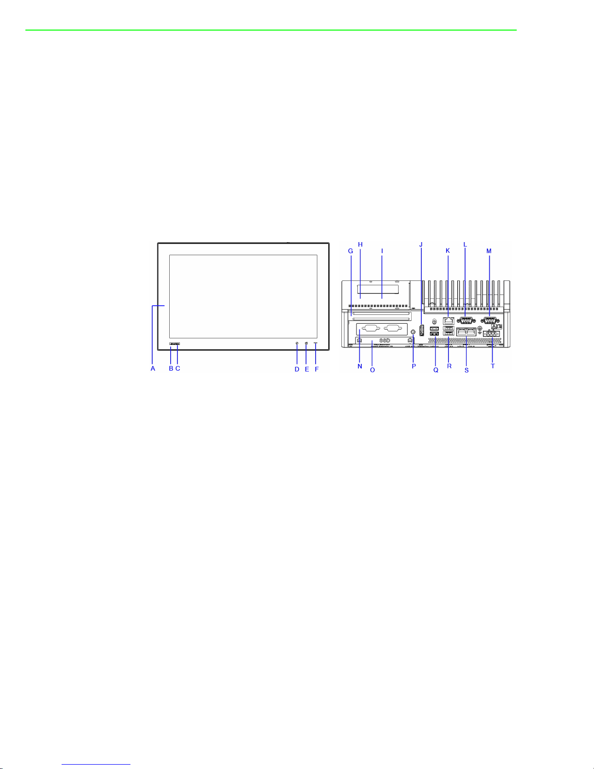
1.5 I/O Port Arrangement
The arrangement of the I/O ports are as shown in Figure 1.1.
Figure 1.1 I/O port arrangement
A. Wi-Fi antenna
B. NFC card reader
C. Logo
D. iKey
E. Home key
F. Power indicator
G. Half-size PCIe
H. M.2 for storage
I. 2 x mPCIe
J. DisplayPort
K. 1 x LAN I219
L. RS-232
M. RS-232/422/485
N. iDoor
O. SSD bay
P. Audio out
Q. 2 x USB 30
R. 2 x USB 2.0
S. 2x LAN I210
T. Power Input
Page 17

5 TPC-5000 Series User Manual
Chapter 1 General Information
1.6 Panel Mounting
1. There is an adhesive waterproof gasket on the Mg front bezel. Ensure that the
waterproof gasket is in place before installing the TPC system in the panel
opening.
2. Install the TPC in the panel opening.
3. Retrieve the clamps and long screws from the accessory pack. Hook the clamps
the holes located on the four sides of the bezel. Insert screws into every clamp
and tighten them to fasten the clamp in place. These screws will push the
mounting panel and secure the unit.
4. The suggested mounting panel thickness is less than 6 mm (0.236 in).
Figure 1.2 Panel mounting
Insert the screws into each clamp and tighten
them to fasten the clamp in place.
Hook the clamps into the holes and fasten the
screws
Torque: 2 kgf-cm
These screws will push the mounting panel and
secure the unit.
Page 18

TPC-5000 Series User Manual 6
1.7 System and Cutout Dimensions
Panel Dimensions (mm) Cutout Size (mm) Wall Thickness (mm)
Display Size X1 Y1 Z1 X2 Y2 Z Min. Z Max.
12" 311.8 238 85.6 303 229 1 6
15" 383.2 307.3 86 374.5 298.5 1 6
17" 410.4 343.4 86.8 401.3 334.8 1 6
18" 488 309 88.8 479.3 300.3 1 6
21.5" 558.4 349.8 88.8 550.3 341.8 1 6
Page 19

Chapter 2
2 System Setup
Page 20

TPC-5000 Series User Manual 8
2.1 Transport and Unpacking
When accepting a delivery, please check the packaging for visible transport damage
and check the delivery for completeness by comparing it with your order form. If you
notice any shipping damage or inconsistencies between the contents and your order,
please inform the responsible delivery service immediately.
During transportation, the TPC system should be protected from excessive mechanical stress. If the TPC system is transported or stored without packaging, shocks,
vibrations, pressure, and moisture may impact the unprotected unit. Additionally,
damaged packaging indicates that ambient conditions have already had a massive
impact on the device. Therefore, please use the original packaging during transportation and storage.
If the TPC system is transported in cold weather or is exposed to extreme variations
in temperature, ensure that moisture (condensation) does not build up on or inside
the HMI device. Moisture can result in short circuits and damage to the device. To
avoid damage, store the TPC system in a dry environment and bring the system to
room temperature before powering it up. If condensation occurs, a delay time of
approximately 12 hours must be allowed to ensure that the system is completely dry
before being switched on.
2.2 System Setup
1. Remove the SSD bay using the blue hand screws.
Figure 2.1 Remove the SSD bay for SSD installation
2. Place the SSD into the bay and affix it in place using the screws provided in the
accessory box.
Figure 2.2 Place the SSD into the bay
Page 21

9 TPC-5000 Series User Manual
Chapter 2 System Setup
3. Attach the box module to the panel module via the board-to-board connector.
Figure 2.3 Attach the box module to the panel module
4. Connect the power connector to 24 V
DC power lines. The power lines can either
be from a power adapter or an in-house power source.
Figure 2.4 Power connector and power lines
Warning! We recommend turning the system power off before adding or removing
a memory card even though the CFast slot supports hot-swapping.
Ilestsuggéré de désactiverl'alimentation du système que vousbran- chez
ouretirez le carte mémoire, mêmesi la mémoire CompactFlash estremplaçable àchaud.
Page 22

TPC-5000 Series User Manual 10
5. Plug the power lines into the system’s power receptor.
Figure 2.5 Power receptor and button pin assignment
6. Connect the power to the system.
7. Calibrate the touchscreen (only applicable for the 12” monitor model).
Page 23

11 TPC-5000 Series User Manual
Chapter 2 System Setup
2.3 Driver Installation
2.3.1 Chipset, Graphics, ME, and LAN Driver Installation
Relevant drivers must be installed for full functionality. Install the chipset, graphics,
ME, and LAN drivers individually. The drivers can be downloaded from the TPC-5000
product page of the Advantech website.
(Windows 7, Windows 8, and Windows 10 have built-in multi-touch driver support.)
2.3.2 Watchdog Driver Installation
If the Advantech watchdog driver is not pre-installed on the TPC system, users will
need to install the driver.
Follow the steps outlined below to install the Advantech watchdog driver.
1. Verify that the computer meets the hardware and software requirements to run
the Advantech watchdog driver.
2. If you do not already have the installer for the Advantech watchdog driver,
download it from the Advantech website.
3. From the Control Panel, remove any existing installation of the Advantech
watchdog driver from the computer.
4. With administrator-level privileges, run the installer for the Advantech watchdog
driver.
Below is an example of the Advantech watchdog driver setup. To stop the setup process at any time, click the “Cancel” button on the pop-up screen. The setup program
will stop the procedure automatically.
1. Open the setup program.When the setup program is running, click the “Next”
button on the Advantech Watchdog Driver Setup Wizard pop-up screen.
2. Wait until the Advantech Watchdog Driver Setup Wizard has completed the
installation.
Page 24

TPC-5000 Series User Manual 12
3. Click the “Install” button to continue the installation of the Advantech watchdog
driver software.
4. Click the “Restart” or “Close” button on the Advantech Watchdog Driver Setup
Wizard pop-up screen to complete the setup.
Page 25

13 TPC-5000 Series User Manual
Chapter 2 System Setup
2.4 Panel Mounting
1. Position the TPC system against the panel.
2. Insert clamps into the sides of the TPC unit.
Page 26

TPC-5000 Series User Manual 14
3. Secure the clamps to the panel using the screws provided in the accessory box.
Page 27

15 TPC-5000 Series User Manual
Chapter 2 System Setup
2.5 Cabinet Installation and Earth Grounding Setup
Follow the steps outlined below to setup the TPC system. Please note that the system’s grounding pin should be connected to an earth ground. This will provide the
system with EMI, ESD, and surge immunity, as well as system isolation. If the TPC
system is embedded in a cabinet, the TPC system’s ground, the cabinet’s ground,
and an earth ground should be connected together.
1. Installing the TPC system in the cabinet.
Step A: Connect the cabinet to an earth ground.
Step B: Embed a null TPC system into the cabinet without an I/O cable or power.
2. Wiring the system.
Step A: Connect the cabinet to an earth ground.
Step B: Ensure that all cabinet devices have been grounded together.
Step C: Connect the ground of the power supply to the cabinet.
Step D: Connect the ground pin of the TPC system to the cabinet.
Step E: Connect the I/O to the controller if needed.
Page 28

TPC-5000 Series User Manual 16
Step F: Connect the V+ and V- of the power supply to the TPC system.
After completing Steps A to F, power should be supplied to the TPC system.
2.6 Power/Digital Ground and Earth Ground
The purpose of power/digital grounding is to block all external interference to the
chassis and prevent any possibility of a bad grounding design causing electric
shocks. This is known as “Level 1 isolation”, which is not implemented on consumergrade PCs.
1. The TPC chassis and earth ground (power pin 3) are short.
2. The TPC chassis and power/digital ground are open.
The TPC system is an industrial-grade product designed to prevent external interference and the possibility of electric shocks. To complete the isolation design, the following must be considered:
1. Because the Ethernet is isolated, a LAN connection will not impact the isolation
design.
2. To resolve EMI and ESD issues, general USB devices are designed as a chas-
sis and digital short. However, the TPC system prevents damage to USB
devices. ESD and EMI solutions are designed to use the power ground as a
vent path to ensure that the power ground and chassis ground do not have difference abnormalities.
3. For COM ports, because there are different COM port designs, long-distance
connections cause voltage differences between the two COM port
chasses.Thus, the cable shell ground must be isolated to the digital ground signal.
In practical cases, many customers may break the Level 1 isolation with a third-party
device or the cable design. In such situations, we must consider making all grounds
(power, digital, and earth) short and ensure that customers have a good earth ground
connection.
Note! Ensure that all wires follow the installation guidelines or damage to the
system may occur.
If you need to install a device or mini PCIe card, double check the volt-
age of V- and the earth ground. If the voltages are not almost equal with
each other, we recommend shorting V- and the earth ground with wiring.
Page 29

17 TPC-5000 Series User Manual
Chapter 2 System Setup
2.7 Extension Installation
2.7.1 Remove the Rear Box
1. Remove the 2 screws on the extension door.
2. Slide the rear cover off to remove it.
Figure 2.6 M.2 SSD installation
3. Remove the screws on the I/O bracket of the rear box module to install an iDoor
module or riser card.
Figure 2.7 Remove the screws on the I/O bracket
Page 30

TPC-5000 Series User Manual 18
2.7.2 M.2 (2280) SSD Installation
Insert the M.2 (2280) SSD and tighten the screws in the screw holes.
Figure 2.8 M.2 SSD installation layout
2.7.3 iDoor Installation
The iDoor module should be affixed in place using two screws that are already set in
the main board. Insert the iDoor module into the slot and plug in the power and signal
cables.
Figure 2.9 iDoor installation
Page 31

19 TPC-5000 Series User Manual
Chapter 2 System Setup
2.7.4 Riser Card Installation
Riser cards should be inserted at the side of the box module through the track. After
insertion, tighten the screws to affix the riser card in place.
Figure 2.10 Riser card installation
2.7.5 SIM Card Installation via Mini PCIe
The SIM card should be inserted into the mini PCIe slot. Tighten the screw after
insertion to affix the SIM card in place.
Figure 2.11 SIM card installation
Page 32

TPC-5000 Series User Manual 20
2.7.6 NFC/RFID and Wi-Fi Module Installation
NFC/RFID and Wi-Fi modules should be installed on the front panel.
1. Open the bracket at the back of the front panel.
2. Insert the Wi-Fi module into the mPCIe slot, connect the antenna, and tighten
the affixing screws.
Figure 2.12 Wi-Fi module installation
3. Plug the USB cable into the NFC/RFID module and affix it in place using an
adhesive.
Figure 2.13 NFC/RFID module installation
Page 33

21 TPC-5000 Series User Manual
Chapter 2 System Setup
Page 34

TPC-5000 Series User Manual 22
Page 35

Chapter 3
3 Features of Windows
Embedded OS
Page 36

TPC-5000 Series User Manual 24
3.1 Features of Windows Embedded OS
The TPC series systems support the embedded Windows OS platform. This chapter
outlines the important features (EWF, FBWF, UWF, and HORM) that are provided in
WES7.
3.2 Enhanced Write Filter (EWF)
Enhanced Write Filter (EWF) and File-Based Write Filter (FBWF) redirect all writes
targeted at protected volumes to a RAM or disk cache, which is known as an overlay.
Although the overlay stores any changes made to the operating system, it is deleted
when the device is restarted, restoring the device to its original state. Note that there
is no disk-based overlay support for Windows Embedded Standard 7.
EWF works at the sector level on protected disks and allows users to implement
changes that persist when the device is restarted. EWF is useful for thin clients that
do not need to store cached information or receive frequent updates. Changes made
to a system protected by EWF are stored in one or more layers that represent snapshots in time. Applying changes to an image applies all changes made to the operating system during a specific period of time.
Advantech provides a utility to run EWF. Follow the steps outlined below to enable
this function.
1. Access Start Menu->All Programs->Advantech-> AdvWF and then click EWF
Utility.
Page 37

25 TPC-5000 Series User Manual
Chapter 3 Features of Windows Embedded OS
2. Access the EWF tab and click on the “Enable” button.
3. After the system is rebooted automatically, EWF functionality will be enabled.
Page 38

TPC-5000 Series User Manual 26
3.3 File-Based Write Filter (FBWF)
File-Based Write Filter (FBWF) works at the file level instead of the sector level on
protected disks. By default, FBWF protects the entire disk. However, selective write
through exceptions can be granted to specific files and folders. Writes to folders with
write-through exceptions will persist when the device is restarted.
Advantech provides a utility to run FBWF. Follow the steps outlined below to enable
this function.
1. Access Start Menu->All Programs->Advantech->AdvWF and the click on
FBWF Utility.
2. Move the volume you want to protect from “Available Volume” to “Protected Vol-
ume” and choose “Write-Through Files and Folders”.
3. Click “Apply”. The system will reboot automatically, after which FBWF will be
enabled.
Page 39

Chapter 4
4 Easy Installation
Page 40

TPC-5000 Series User Manual 28
4.1 Easy Installation
With the easy installation design, a single person can complete the panel mount process. Simply follow the steps outlined below.
To install the TPC system into a cabinet
Step 1:
Models with a 4:3 screen ratio
1. Use the snap hooks at the top of the TPC unit to hook the system in the cabinet.
2. Release the pillars at the bottom of the TPC unit to install the system in the cab-
inet.
Models with a 16:9 screen ratio
1. Remove the screws and use the snap hooks to hook the TPC unit in the cabinet.
2. Release the pillars at the bottom of the TPC unit for balancing in the cabinet.
Page 41

29 TPC-5000 Series User Manual
Chapter 4 Easy Installation
Step 2:
1. Place the TPC unit across the cabinet wall.
2. Push the upper part of the system towards the wall until the snap hooks flip
back. The snap hooks will hold the machine on the wall.
To remove the panel from a cabinet
1. For cabinets with a thickness of 2 mm or less, use a Ø≤ 4 mm stick to pull out
the panel. For cabinets with a thickness of more than 2 mm, push the snap
hooks to pull out the panel. Remember to hold the panel securely when pushing
the snap hooks to release the panel.
Page 42

TPC-5000 Series User Manual 30
4.2 UI Operation
This section provides instructions for operating the HMI utility (GL_Utility), which can
be downloaded from Advantech's TPC product support portal at
http://support.advantech.com.
1. Located at the lower right corner of the front panel are two function buttons – the
iKey and the home key. The icon represents the iKey, while represents the home key.
Note! For easy installation, the suggested mount panel thickness should be
less than 2 mm (0.079 in). For standard installation, the suggested
mount panel thickness should be less than 6 mm(0.236 in).
Table 4.1: Status Indicator Table
Indicator Status
Green Power on
Orange Standby
No light Off
Page 43

31 TPC-5000 Series User Manual
Chapter 4 Easy Installation
2. Single press of the home key->
Home – Back to desktop (default setting)
Home - Execute home-key app (setup via the settings page)
3. Long press of the home key->
Home - Long press to disable/enable touch function
Page 44

TPC-5000 Series User Manual 32
4. Single press of the iKey ->
GLToolbar Utility
A. Quick start->
– Press “+” to add a shortcut
– Long press the iKey to perform a “right click” until an “X” mark appears in
upper right corner to “delete”
Page 45

33 TPC-5000 Series User Manual
Chapter 4 Easy Installation
B. Setting ->
– A password is required for authorization confirmation upon initial login. The
default password is “1234” without an input order to activate.
– Setting - Home key: Select an executable file to set as the home key app.
The default path destination is desktop
– Setting - Brightness: Brightness control from 1 to 8
– Setting - Password: Change password function
Page 46

TPC-5000 Series User Manual 34
C. System management->
– System information
– Self diagnosis
Note!* TPC-5000 series also provides open button code as following definition
for customer's configuration to their Apps/SW applications. The codes
are defined from general keyboard input.
Table 4.2: Button Code Definition
Single Press Long Press
iKey (icon)
Ctrl+Shift+Alt+I Ctrl+Shift+Alt+U
Home Key (icon)
Ctrl+Shift+Alt+H Ctrl+Shift+Alt+L
Page 47

35 TPC-5000 Series User Manual
Chapter 4 Easy Installation
4.3 COM1: RS-232
Pin Definition
COM1
4.4 COM2: RS-422/485
The COM2 serial ports on the TPC series systems can be adjusted via the BIOS
menu and set to RS-422 or RS-485 mode. This port is designed with automatic data
flow control capabilities. In other words, the TPC series systems can automatically
detect the data flow direction at this port when two-wire RS-485 communication is
activated.
Pin Definition
COM 2
Pin Signal
1 DCD
2RX
3TX
4DTR
5GND
6DSR
7RTS
8CTS
9RI
Pin
Signal
RS-422 RS-485
1TX-D-
2TX+D+
3 Rx+ –
4 Rx- –
5GNDGND
6––
7––
8––
9––
Page 48

TPC-5000 Series User Manual 36
4.5 RS-422/ 485 Mode Setting via BIOS
1. Restart the system and press the “Delete” key to enter the BIOS setup utility.
2. Access the “Advanced” tab and select “IT8768E Super IO Configuration”.
Page 49

37 TPC-5000 Series User Manual
Chapter 4 Easy Installation
3. Select the “Serial Port 2 Configuration (COM2)” option to configure the RS-422/
485 mode.
4. Select the “RS-422/485 mode” option.
Page 50

TPC-5000 Series User Manual 38
Page 51

39 TPC-5000 Series User Manual
Chapter 4 Easy Installation
Page 52

www.advantech.com
Please verify specifications before quoting. This guide is intended for reference
purposes only.
All product specifications are subject to change without notice.
No part of this publication may be reproduced in any form or by any means,
such as electronically, by photocopying, recording, or otherwise, without prior
written permission from the publisher.
All brand and product names are trademarks or registered trademarks of their
respective companies.
© Advantech Co., Ltd. 2018
 Loading...