

Page 1

User Manual
PPC-L128T
Intel® AtomTM N270 Processorbased Fanless Panel PC with
12.1" TFT-LCD
Page 2

Copyright
The documentation and the software included with this product are copyrighted
2009by Advantech Co., Ltd. All rights are reserved. Advantech Co., Ltd. reserves the
right to make improvements in the products described in this manual at any time without notice. No part of this manual may be reproduced, copied, translated or transmitted in any form or by any means without the prior written permission of Advantech
Co., Ltd. Information provided in this manual is intended to be accurate and reliable.
However, Advantech Co., Ltd. assumes no responsibility for its use, nor for any
infringements of the rights of third parties, which may result from its use.
Acknowledgements
Award is a trademark of Award Software International, Inc. Intel and Celeron are
trademarks of Intel Corporation.
IBM, PC/AT, PS/2 and VGA are trademarks of International Business Machines Corporation.
Intel and Pentium are trademarks of Intel Corporation.
Microsoft Windows is a registered trademark of Microsoft Corp. RTL is a trademark of
Realtek Semiconductor Co., Ltd.
All other product names or trademarks are properties of their respective owners.
For more information on this and other Advantech products, please visit our websites
at:
http://www.advantech.com
http://www.advantech.com/ppc
For technical support and service, please visit our support website at:
http://support.advantech.com
This manual is for the PPC-L128T.
Part No. 200K128T10 Edition 1
Printed in China November 2009
PPC-L128T User Manual ii
Page 3

Declaration of Conformity
FCC Class B
Note: This equipment has been tested and found to comply with the limits for a Class
B digital device, pursuant to part 15 of the FCC Rules. These limits are designed to
provide reasonable protection against harmful interference in a residential installation. This equipment generates, uses and can radiate radio frequency energy and, if
not installed and used in accordance with the instructions, may cause harmful interference to radio communications. However, there is no guarantee that interference
will not occur in a particular installation. If this equipment does cause harmful interference to radio or television reception, which can be determined by turning the equipment off and on, the user is encouraged to try to correct the interference by one or
more of the following measures:
Reorient or relocate the receiving antenna.
Increase the separation between the equipment and receiver.
Connect the equipment into an outlet on a circuit different from that to which the
receiver is connected.
Consult the dealer or an experienced radio/TV technician for help.
Warning! Any changes or modifications made to the equipment which are not
expressly approved by the relevant standards authority could void your
authority to operate the equipment.
iii PPC-L128T User Manual
Page 4

Packing List
Before you begin installing your card, please make sure that the following materials
have been shipped:
PPC-L128T series panel PC
User manual
Accessories for PPC-L128T
– Y-shaped adapter for PS/2 mouse and keyboard
– Warranty card
– DC plug-in housing (female) is connected on the AC/DC power adapter
– Driver DVD-RW disc
– Mounting kits and packet of screws
If any of these items are missing or damaged, contact your distributor or sales representative immediately.
Additional Information and Assistance
1. Visit the Advantech web site at www.advantech.com where you can find the lat-
est information about the product.
2. Contact your distributor, sales representative, or Advantech's cus- tomer service
center for technical support if you need additional assistance. Please have the
following information ready before you call:
Product name and serial number
Description of your peripheral attachments
Description of your software (operating system, version, application soft-
ware, etc.)
A complete description of the problem
The exact wording of any error messages
Caution! Danger of explosion if battery is incorrectly replaced. Replace only with
the same or equiv- alent type recommended by the manufacturer. Dispose of used batteries according to the manufacturer's instructions.
Warning! 1. Input voltage rated 12 ~ 24 V, 5 A ~ 3.75 A
2. Use a 3 V @ 195 mA lithium battery
3. Packing: please carry the unit with both hands, handle with care
4. Maintenance: to properly maintain and clean the surfaces, use only
approved products or clean with a dry applicator
5. CompactFlash: Turn off power before insert- ing or removing Com-
pactFlash storage card.
Contact information:
Our European representative: Advantech Europe GmbH Kolberger
Strafle 7
D-40599 Dsseldorf, Germany
Tel: 49-211-97477350
Fax: 49-211-97477300
PPC-L128T User Manual iv
Page 5

Safety Instructions
1. Read these safety instructions carefully.
2. Keep this User Manual for later reference.
3. Disconnect this equipment from any AC outlet before cleaning. Use a damp
cloth. Do not use liquid or spray detergents for cleaning.
4. For plug-in equipment, the power outlet socket must be located near the equip-
ment and must be easily accessible.
5. Keep this equipment away from humidity.
6. Put this equipment on a reliable surface during installation. Dropping it or letting
it fall may cause damage.
7. The openings on the enclosure are for air convection. Protect the equipment
from overheating. DO NOT COVER THE OPENINGS.
8. Make sure the voltage of the power source is correct before connecting the
equipment to the power outlet.
9. Position the power cord so that people cannot step on it. Do not place anything
over the power cord.
10. All cautions and warnings on the equipment should be noted.
11. If the equipment is not used for a long time, disconnect it from the power source
to avoid damage by transient overvoltage.
12. Never pour any liquid into an opening. This may cause fire or electrical shock.
13. Never open the equipment. For safety reasons, the equipment should be
opened only by qualified service personnel.
14. If one of the following situations arises, get the equipment checked by service
personnel:
The power cord or plug is damaged.
Liquid has penetrated into the equipment.
The equipment has been exposed to moisture.
The equipment does not work well, or you cannot get it to work according to
the user's manual.
The equipment has been dropped and damaged.
The equipment has obvious signs of breakage.
15. DO NOT LEAVE THIS EQUIPMENT IN AN ENVIRONMENT WHERE THE
STORAGE TEMPERATURE MAY GO BELOW -20° C (-4° F) OR ABOVE 60° C
(140° F). THIS COULD DAMAGE THE EQUIPMENT. THE EQUIPMENT
SHOULD BE IN A CONTROLLED ENVIRONMENT.
16. CAUTION: DANGER OF EXPLOSION IF BATTERY IS INCORRECTLY
REPLACED. REPLACE ONLY WITH THE SAME OR EQUIVALENT TYPE
RECOMMENDED BY THE MANUFACTURER, DISCARD USED BATTERIES
ACCORDING TO THE MANUFACTURER'S INSTRUCTIONS.
The sound pressure level at the operator's position according to IEC 704-1:1982 is
no more than 70 dB (A).
DISCLAIMER: This set of instructions is given according to IEC 704-1. Advantech
disclaims all responsibility for the accuracy of any statements contained herein.
v PPC-L128T User Manual
Page 6

PPC-L128T User Manual vi
Page 7

Contents
Chapter 1 General Information ............................1
1.1 Introduction ............................................................................................... 2
1.2 General Specifications .............................................................................. 2
1.2.1 General ......................................................................................... 2
1.2.2 Standard PC functions .................................................................. 2
1.2.3 VGA/LCD Interface ....................................................................... 3
1.2.4 Audio function ............................................................................... 3
1.2.5 PCIe bus Ethernet interface.......................................................... 3
1.2.6 Touchscreen (Optional) ................................................................ 3
1.2.7 Optional modules .......................................................................... 4
1.2.8 Environment.................................................................................. 4
1.3 LCD Specifications.................................................................................... 4
1.4 Dimensions ............................................................................................... 5
Figure 1.1 Dimensions of PPC-L128T ......................................... 5
Chapter 2 System Setup.......................................7
2.1 A Quick Tour of the Panel PC ................................................................... 8
Figure 2.1 Front view of PPC-L128T panel PC ........................... 8
Figure 2.2 Rear view of Panel PC ............................................... 8
Figure 2.3 Side view of the panel PC .......................................... 9
Figure 2.4 Bottom view of the panel PC ...................................... 9
2.2 Installation Procedures.............................................................................. 9
2.2.1 Connecting the power cord ........................................................... 9
2.2.2 Connecting the keyboard or mouse .............................................. 9
2.2.3 Switching on the power............................................................... 10
Figure 2.5 Connect the power cord to the DC inlet.................... 10
2.3 Running the BIOS Setup Program .......................................................... 10
2.4 Installing System Software...................................................................... 11
2.4.1 Method 1: Use the Ethernet ........................................................ 11
2.4.2 Method 2: Use the COM ............................................................. 11
2.4.3 Method 3: Use a DVD-RW.......................................................... 11
2.5 Installing the Drivers................................................................................ 11
Chapter 3 Hardware Installation and Upgrading..
13
3.1 Introduction ............................................................................................. 14
3.2 Installing the 2.5" Hard Disk Drive (HDD) ............................................... 14
Figure 3.1 Installing primary 2.5" HDD ...................................... 14
3.3 Installing the battery pack ....................................................................... 15
Figure 3.2 Installing the battery pack......................................... 15
Chapter 4 Jumper Settings and Connectors ....17
4.1 Jumpers and Connectors ........................................................................ 18
4.1.1 Setting jumpers ........................................................................... 18
4.1.2 Jumpers and connectors............................................................. 19
Table 4.1: Jumpers and Connector functions............................ 19
4.1.3 Locating jumpers and connectors ............................................... 20
Figure 4.1 Jumpers and Connectors on the PPC-L128T mother-
vii PPC-L128T User Manual
Page 8

board ........................................................................ 20
4.2 CMOS Clear for External RTC (CN13(2-3))............................................ 20
Table 4.2: CMOS clear (CN13) ................................................. 20
4.2.1 COM1/COM2/COM3 pin 9 output setting (CN20&CN21) ........... 21
Table 4.3: COM1/ COM2 pin 9 output setting (CN20).............. 21
Table 4.4: COM3 pin 9 output setting (CN21) .......................... 21
4.3 VGA Interface ......................................................................................... 21
4.3.1 LCD panel power setting ............................................................ 21
Appendix A I/O Pin Assignments ......................... 23
A.1 Keyboard and PS/2 Mouse Connector (CN27)....................................... 24
Table A.1: Keyboard and mouse connector (CN27).................. 24
A.2 USB port (CN19)..................................................................................... 24
Table A.2: USB port (CN19) ...................................................... 24
A.3 COM1 RS-232 serial port (CN37) ........................................................... 24
Table A.3: COM1 RS-232 serial port (CN37) ............................ 24
A.4 COM2 (CN28) ......................................................................................... 25
Table A.4: COM2 (CN28) ......................................................... 25
A.5 COM3 RS-232 serial port (CN38) ........................................................... 25
Table A.5: COM3 RS-232 serial port (CN38) ............................ 25
A.6 GPIO port (CN29) ................................................................................... 26
Table A.6: GPIO port (CN29)..................................................... 26
A.7 VGA Connector (CN39) .......................................................................... 26
Table A.7: VGA connector (CN39) ............................................ 26
A.8 PCI Bus connector (CN18) ..................................................................... 27
Figure A.1 PCI connector........................................................... 27
Table A.8: PCI pin assignments ................................................ 28
A.9 PCI Express Bus connector (CN16) ....................................................... 29
Table A.9: PCIExpress pin assignments ................................... 29
A.10 How to setup Teaming function on PPC-L128/L157............................... 30
A.10.1 Team together ............................................................................ 30
A.10.2 Dismiss! ...................................................................................... 35
A.10.3 TESTING .................................................................................... 37
PPC-L128T User Manual viii
Page 9

Chapter 1
1 General Information
This chapter gives background
information on the PPC-L128T
panel PC.
Sections include:
Introduction
General Specifications
LCD Specifications
Dimensions
Page 10

1.1 Introduction
The PPC-L128T panel PC is an Intel low-power Intel® AtomTM N270 processor computer that is designed to serve as a human machine interface (HMI) and as a multimedia computer. It is a PC-based system with 12.1" color TFT LCD display, on-board
PCIe Ethernet controller, multi-COM port interfaces and an audio controller. With a
built in internal IDE connector (for CF card), One SATA connector for HDD and one
for ODD,and an PCI/PCIe expansion socket, the PPC-L128T is as compact and user
friendly as a multifunction computer. In addition, its “fit anywhere” design makes it
very flexible and able to be used in many different kinds of installations. It can be wall
mounted, panel mounted or stood upright on a desktop.
For system integrators, this simple, complete, compact and highly integrated multimedia system lets you easily build a panel PC into your applications. Common industrial applications include factory automation systems, precision machinery, and
production process control. It is also suitable for many nonindustrial applications,
including interactive kiosk systems, entertainment management, and car park automation. Our panel PC is a reliable, cost-effective solution to your application's processing requirements.
1.2 General Specifications
1.2.1 General
Dimensions (W x H x D): 340.5 x 269.3 x 70.5 mm
Weight: 3.63 kg
– Power supply: ATX type
– Input Voltage: +12 ~ 24 VDC, 5 A ~ 3.75 A
– Power adaptor: AC/DC (Optional PS-DC19-L157E ) Input voltage: 100 ~ 240
VAC
– Output voltage: 19 V @ 4.74 A
Disk drive housing: Space for one 2.5" SATA HDD, one slim type DVD-RW
Front panel: IP65/NEMA4 compliant
1.2.2 Standard PC functions
CPU: On board Intel® AtomTM N270, 1.6 GHz with 512 L2 cache
BIOS: Award 8 Mbit flash BIOS, ACPI 2.0 Compliant
System Chipset: Intel® 945GSE + Intel ICH7M
Front side bus: 533 MHz
2nd level cache: 512 KB
System Memory: One 200-pin SO-DIMM socket, accepting up to 2 GB DDR2
400/ 533
PCI bus interface: PCI 33MHz/32Bit Supports one connectors.
Keyboard/mouse connector: Supports PS/2 Keyboard and Mouse
GPIO port: One GPIO port supports controller and surveillance function.
Serial ports: Three serial ports with two RS-232 ports (COM 1 and 3), one RS-
232/422/485 port (COM2). All ports are compatible with 16C550 UARTs, +5 V
(0.5 A) / +12 V (0.5 A) power supply selectable
Universal serial bus (USB) port: Support Up to 6 USB V2.0 ( 4 x external, 2 x
internal.
PCIe bus expansion slot: Accepts one PCIe card
PPC-L128T User Manual 2
Page 11

Mini PCIe bus expansion slot: Accepts one mini PCIe bus card(Wire less LAN
card)
Solid State Disk: Supports one 50-pin socket for CompactFlash type I/II (True
IDE mode)
Watchdog timer: 255-level timer intervals, from 15 sec to 14835 sec, setup by
software, jumperless selection, generates system reset
Battery: 3.0 V @ 195 mA lithium battery
Power management: Supports power saving modes including S0:Normal/
S1:Standby/S3:Suspend modes. APM 1.2 compliant
1.2.3 VGA/LCD Interface
Chipset: Integrated in Intel 945GSE
Frame buffer: Supports 128MB frame buffer with system memory
Interface: VGA/ LCD interface, support for 18-bit TFT
Display mode: CRT Modes: 2048 x 1536 @ 32bpp (60Hz);
LCD/Simultaneous Modes: 1024 x768 @ 16bpp (60 Hz)
1.2.4 Audio function
Chipset: Intel ICH7M South Bridge
Audio controller: ALC888 HD Audio Ver 2.0 compliant interface, Multi- stream
Direct sound and Direct Sound 3D acceleration
Stereo sound: 24-bit full-duplex codec
Audio interface: Microphone in, Line in, Line out, Speaker L, Speaker R
Chapter 1 General Information
1.2.5 PCIe bus Ethernet interface
Chipset: Marvell 88E8053-A3-NNC1C000 PCIe local bus Ethernet controller
Ethernet interface: Full compliance with IEEE 802.3, 1000Base-T 100Base-T
and 10 Base-T specifications.Support 802.1p, 802.1q. Includes software drivers
and boot ROM
1000/100/10Base-T auto-sensing capability
Wake-on-LAN: Supports Wake-on-LAN function with ATX power control
Teaming Function: Support Teaming Function(refer to A.10)
1.2.6 Touchscreen (Optional)
Type Analog Resistive
Resolution Continuous
Light Transmission 80%
Controller USB interface
Power Consumption <5 V @ 60 mA
Software Driver Supports Windows 2000/XP
Durability
(touches in a lifetime)
35 million
3 PPC-L128T User Manual
Page 12

1.2.7 Optional modules
Memory: One 200-pin SO-DIMM socket, accepting up to 2 GB DDR2 400/533
DVD-RW Module: Slim type
Combo Module: Slim type Combo Module 989KL128T01E
Wireless LAN module: 989KL128T02E (Build in IEEE 802.11b/g AzureWave
AW-NE768 Mi MINI PCIe card)
Adaptor: PS-DC19-L157E
HDD: 2.5" SATA HDD
Operating System: Windows XP,Vista
Touchscreen: Analog resistive(PPC-L128T-R80-XE)
Battery pack: Rechargable Li-ion 3S2P 11.1 V 4400 mAh(1760000837)
1.2.8 Environment
Operating Temperature: 0 ~ 45° C (32 ~ 113° F)
Operating Temperature with battery: 0 ~ 35° C (32 ~ 95° F)
Storage Temperature: -20 ~ 60° C
Relative humidity: 10 ~ 95% @ 40° C (non-condensing)
Shock: 10 G peak acceleration (11 ms duration)
Certification: EMC: CE, FCC, BSMI, VCCI. Safety: UL 60950, CB, CCC, BSMI
Vibration: 5 ~ 500 Hz 1 G RMS Random vibration
DVD-RW Module 989KL128T00E
1.3 LCD Specifications
Display type: 12.1" TFT LCD
Max. resolution: 1024 x 768
Colors: 262 K
Dot size (mm): 0.24 x 0.24
Viewing angle: 80° (left), 80° (right), 80° (up), 80° (down)
Luminance: 450 cd/m
Temperature: -30 ~ 70° C
*VR control: Brightness could be modified through BIOS
Backlight lifetime: 50,000 hours
* The VR control is defined by hot key in DOS or BIOS mode as below: Ctrl-Alt-
F3, Ctrl-Alt-F4.
Note! The color LCD display installed in the panel PC is high-quality and reli-
able. However, it may contain a few defective pixels which do not
always illuminate. With current technology, it is impossible to completely
eliminate defective pixels. Advantech is actively working to improve this
technology.
2
PPC-L128T User Manual 4
Page 13
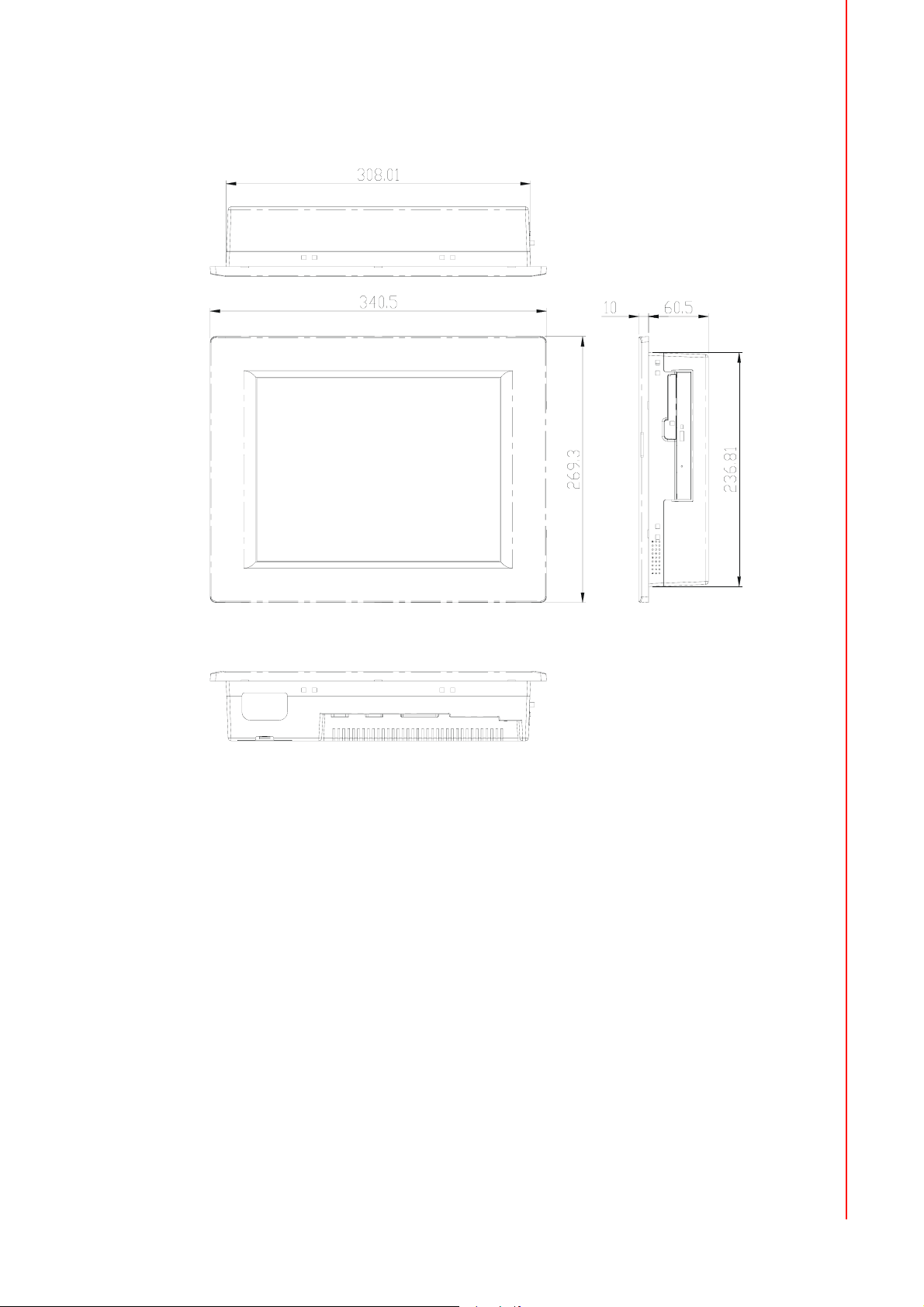
1.4 Dimensions
Chapter 1 General Information
Unit: mm [inch]
Figure 1.1 Dimensions of PPC-L128T
5 PPC-L128T User Manual
Page 14

PPC-L128T User Manual 6
Page 15

Chapter 2
2 System Setup
This chapter details system setup
on the PPC-L128T panel PC.
Sections include:
A Quick Tour of the Panel PC
Installation procedures
Running the BIOS Setup Pro-
gram
Installing System Software
Installing the Drivers
Page 16

2.1 A Quick Tour of the Panel PC
Before you start to set up the panel PC, take a moment to become familiar with the
locations and purposes of the controls, drives, connectors and ports, which are illustrated in the figures below.
When you place the panel PC upright on the desktop, its front panel appears as
shown in Figure 2.1.
Figure 2.1 Front view of PPC-L128T panel PC
When you turn the panel PC around and look at its rear cover, you will find the I/O
section as shown in Fig. 2.2. (The I/O section includes vari- ous I/O ports, including
serial ports, the Ethernet port, USB ports, the Line-in/Line-out jack, and so on.) The
battery door cover is at the bottom of the panel PC, as shown in Fig. 2.4.
PCI/PCIe expansion
slot cover
Ethernet jack
USB 2.0 x 3
Main power switch
Line-in jack
Line-out jack
Mic-in jack
USB 2.0
Ethernet jack
VGA port
PS2 mouse
and keyboard
GPIO port
DC inlet
Serial ports
Figure 2.2 Rear view of Panel PC
PPC-L128T User Manual 8
Page 17

CompactFlash socket
Chapter 2 System Setup
Compact DVD-RW drive
DVD-RW activity light
CFC eject button
Door Cover
DVD-RW eject button
Speaker
Figure 2.3 Side view of the panel PC
Battery
Figure 2.4 Bottom view of the panel PC
2.2 Installation Procedures
2.2.1 Connecting the power cord
The panel PC can be powered by a DC electrical outlet or the battery. Be sure to
always handle the power cords by holding the plug ends only. Please follow the Figure 2-5 to connect the male plug of the power cord to the DC inlet of the panel PC.
2.2.2 Connecting the keyboard or mouse
Before you start the computer, please connect the Y-shaped adaptor to the PS/2
mouse and keyboard port on the I/O section of the panel PC, then connect the necessary mouse or keyboard to the Y-shaped adapter or
serial ports.
9 PPC-L128T User Manual
Page 18

2.2.3 Switching on the power
When you look at the rear side of the panel PC, you will see the power switch as
shown in Figure 2.2.
Power cord
Figure 2.5 Connect the power cord to the DC inlet
AC/DC Power adapter
2.3 Running the BIOS Setup Program
Your panel PC is likely to have been properly set up and configured by your dealer
prior to delivery. You may still find it necessary to use the panel PC's BIOS (Basic
Input-Output System) setup program to change system configuration information,
such as the current date and time or
your type of hard drive. The setup program is stored in read-only memory (ROM). It
can be accessed either when you turn on or reset the panel PC, by pressing the ‘Del’
key on your keyboard immediately after powering on the computer.
The settings you specify with the setup program are recorded in a special area of
memory called CMOS RAM. This memory is backed up by a battery so that it will not
be erased when you turn off or reset the system. Whenever you turn on the power,
the system reads the settings stored in CMOS RAM and compares them to the
equipment check conducted during the power on self-test (POST). If an error occurs,
an error message will be displayed on screen, and you will be prompted to run the
setup program.
If you want to change the setup of BIOS, refer to Chapter 9 for more detailed information.
DC inlet
PPC-L128T User Manual 10
Page 19

2.4 Installing System Software
Recent releases of operating systems from major vendors include setup programs
which load automatically and guide you through hard disk preparation and operating
system installation. The guidelines below will help you determine the steps necessary
to install your operating system on the panel PC hard drive.
Note! Some distributors and system integrators may have already pre-
installed system software prior to shipment of your panel PC.
Installing software requires an installed HDD. Software can be loaded in the PPCL128T using any of four methods:
2.4.1 Method 1: Use the Ethernet
You can use the Ethernet port to download software to the HDD.
2.4.2 Method 2: Use the COM
You can use Lap Link 6 or similar transmission software. Connect
another PC to the PPC-L128T with an appropriate cable and transmit the software to
the PPC-L128T.
Chapter 2 System Setup
2.4.3 Method 3: Use a DVD-RW
If required, insert your operating system's installation or setup diskette into the diskette drive until the release button pops out.
The BIOS of the panel PC supports system boot-up directly from the DVD-RW drive.
You may also insert your system installation DVD-RW into the DVD-RW drive.
Power on your panel PC or reset the system by pressing the ‘Ctrl+Alt+Del’ keys
simultaneously. The panel PC will automatically load the operating system from the
diskette or DVD-RW.
If you are presented with the opening screen of a setup or installation pro- gram, follow the instructions on screen. The setup program will guide you through preparation
of your hard drive, and installation of the operaing system. If you are presented with
an operating system command prompt, such as A:\>, then you must partition and format your hard drive, and manually copy the operating system files to it. Refer to your
operat- ing system user manual for instructions on partitioning and formatting a hard
drive.
2.5 Installing the Drivers
After installing your system software, you will be able to set up the Ether- net, SVGA,
audio, and touchscreen functions. All drivers are stored in a DVD-RW disc entitled
“Drivers and Utilities” which can be found in your accessory box.
The various drivers and utilities in the DVD-RW disc have their own text files which
help users install the drivers and understand their functions. These files are a very
useful supplement to the information in this manual.
Note! The drivers and utilities used for the PPC-L128T panel PCs are subject
to change without notice. If in doubt, check Advantech's website or contact our application engineers for the latest informa- tion regarding drivers and utilities.
11 PPC-L128T User Manual
Page 20

PPC-L128T User Manual 12
Page 21

Chapter 3
3 Hardware Installation
and Upgrading
This chapter details installing the
PPC- L128T panel PC hardware.
Sections include:
Overview of Hardware Installa-
tion and Upgrading
Installing the 2.5" Hard Disk
Drive (HDD)
Installing the battery pack
Page 22

3.1 Introduction
The panel PC consists of a PC-based computer that is housed in a plastic rear panel
and a metal shielding case. You can install a HDD, DRAM, and battery pack by
removing the rear panel and shielding case. Any maintenance or hardware upgrades
can be easily completed after remov- ing the rear panel and shielding case.
If you are a systems integrator and need to know how to completely dis- assemble
the panel PC, you can find more useful information in Appendix C.
Warning! Do not remove the plastic rear cover until you have verified that no
power is flowing within the panel PC. Power must be switched off and
the power cord must be unplugged. Every time you service the panel
PC, you should be aware of this.
3.2 Installing the 2.5" Hard Disk Drive (HDD)
You can attach one Serial Advanced Technology Attachment (SATA) hard disk drive
to the panel PC's internal controller. The SATA controller supports faster data transfer
and allows the SATA hard drive to exceed 150 MB. The following are instructions for
installation:
1. Detach and remove the plastic rear cover.
2. There is a metal brace which holds the HDD to the upper left-hand side of the
metal shielding case. (See Fig. 3.1.)
3. Place the HDD in the metal brace, and tighten the screws.
4. The HDD cable (SATA 7P+1*5P-2.5/SATA(15+7)P) is next to the metal brace.
Connect the HDD cable to the PC board (CN5&CN6). Plug the other end of the
cable into the SATA hard drive.
5. Put the plastic rear cover on and tighten the screws.
Figure 3.1 Installing primary 2.5" HDD
PPC-L128T User Manual 14
Plastic rear cover
Page 23

3.3 Installing the battery pack
1. Pull up the battery door cover on the right bottom of PPC-L128T.
2. Put the battery pack in, and then connect the battery cable to battery connector
in the PPC-L128T. Make sure the red wire corresponds to Pin 1 on the connector.
3. Close the battery door cover.
Battery door cover
Red color (pin1)
Battery pack
Chapter 3 Hardware Installation and Upgrading
Battery cable
Figure 3.2 Installing the battery pack
15 PPC-L128T User Manual
Page 24

PPC-L128T User Manual 16
Page 25

Chapter 4
4 Jumper Settings and
Connectors
This chapter tells how to set up
the panel PC hardware, including
instructions on setting jumpers
and connecting peripherals,
switches and indicators. Be sure
to read all the safety precautions
before you begin the installation
procedures.
Sections include:
Jumpers and Connectors
CMOS Clear for External RTC
(J5)
COM Port Interface
VGA Interface
Watchdog Timer Configuration
Page 26

4.1 Jumpers and Connectors
4.1.1 Setting jumpers
You can configure your panel PC to match the needs of your application by setting
jumpers. A jumper is the simplest kind of electrical switch. It consists of two metal
pins and a small metal clip (often protected by a plastic cover) that slides over the
pins to connect them. To “close” a jumper, you connect the pins with the clip. To
“open” a jumper you remove the clip. Sometimes a jumper will have three pins,
labeled 1, 2 and 3. In this case, you would connect either pins 1 and 2 or pins 2 and
3.
open closed closed 2-3
The jumper settings are schematically depicted in this manual as follows:.
1 23
open closed closed 2-3
A pair of needle-nose pliers may be helpful when working with jumpers.
If you have any doubts about the best hardware configuration for your application,
contact your local distributor or sales representative before you make any changes.
PPC-L128T User Manual 18
Page 27

4.1.2 Jumpers and connectors
The motherboard of the PPC-L128T has a number of jumpers and connectors that
allow you to configure your system to suit your applications. The table below lists the
function of each of the board’s jumpers.
Table 4.1: Jumpers and Connector functions
CN1 LVDS connector
CN3 Inverter power connector
CN4 CF Slot ,TYPEII
CN5 SATA HDD signal connector (2.5" HDD)
CN6 SATA HDD power connector (2.5" HDD)
CN7 DDR2 SO-DIMM
CN8 MINI PCIe slot
CN9 5 Wires T/S connector
CN11 SATA ODD signal connector
CN12 SATA ODD power connector
CN16 PCIe (x1) slot
CN18 PCI bus expansion slot
CN19 Internal USB connector
CN23 Internal Speaker connector
CN33 Internal power connector
CN40 LCD light sensor connector
CN41 Front panel connector
PCN1 Battery connector
CN13 Clear CMOS connector
CN14 AT/ATX selection connector
CN20 COM1/2 Pin9 function selection
CN21 COM3 Pin9 function selection
Chapter 4 Jumper Settings and Connectors
19 PPC-L128T User Manual
Page 28

4.1.3 Locating jumpers and connectors
Figure 4.1 Jumpers and Connectors on the PPC-L128T motherboard
4.2 CMOS Clear for External RTC (CN13(2-3))
Warning! To avoid damaging the computer, always turn off the power supply
before setting "Clear CMOS". Set the jumper back to "Normal operation"
before turning on the power supply.
This jumper is used to erase CMOS data and reset system BIOS informa- tion.
The procedure for clearing CMOS is:
1. Turn off system.
2. Short pin 2 and pin 3.
3. Return jumper to pins 1 and 2.
4. Turn on the system. The BIOS is now reset to its default setting.
Table 4.2: CMOS clear (CN13)
* Normal operation Clear CMOS
* Default normal operation setting
PPC-L128T User Manual 20
Page 29

4.2.1 COM1/COM2/COM3 pin 9 output setting (CN20&CN21)
Table 4.3: COM1/ COM2 pin 9 output setting (CN20)
CN20
Default Ring function
1 3 5 7 9
2 4 6 8 10
* +5V output
1 3 5 7 9
2 4 6 8 10
Chapter 4 Jumper Settings and Connectors
* +12V output
1 3 5 7 9
2 4 6 8 10
Note! Pins 1, 3, 5, 7 and 9 are dedicated to COM1.
Pins 2, 4, 6, 8 and 10 are dedicated to COM2.
Table 4.4: COM3 pin 9 output setting (CN21)
CN21
Default Ring function
Ring function (1-2) Output 5 V(3-4) Output 12 V(4-5)
1 5
1 5
1 5
4.3 VGA Interface
4.3.1 LCD panel power setting
The panel PC's AGP SVGA interface supports 12V LCD displays. The LCD cable
already has a built-in default setting. You do not need to adjust any jumper or switch
to select the panel power.
21 PPC-L128T User Manual
Page 30

PPC-L128T User Manual 22
Page 31

Appendix A
A I/O Pin Assignments
Page 32

A.1 Keyboard and PS/2 Mouse Connector (CN27)
Table A.1: Keyboard and mouse connector (CN27)
Pin Signal
1 KB_DATA
2MS-DATA
3GND
4+5 V
5 KB_CLK
6MS-CLK
A.2 USB port (CN19)
Table A.2: USB port (CN19)
Pin Signal
1 +V5_USB
3DATA-
5DATA+
7GND
9GND
2 +V5_USB
4DATA-
6DATA+
8GND
10 GND
A.3 COM1 RS-232 serial port (CN37)
Table A.3: COM1 RS-232 serial port (CN37)
Pin Signal Pin Signal
1 DCD# 2 RX
3TX 4DTR#
5GND 6DSR#
7RTS# 8CTS#
9RI#
PPC-L128T User Manual 24
Page 33

A.4 COM2 (CN28)
Table A.4: COM2 (CN28)
Pin Signal RS-232 RS-422 RS-485
1 DCD TX- DATA-
2RX TX+ DATA+
3TX RX+
4DTR RX-
5GND GND
6DSR
7RTS
8CTS
9RI
Appendix A I/O Pin Assignments
A.5 COM3 RS-232 serial port (CN38)
Table A.5: COM3 RS-232 serial port (CN38)
Pin Signal Pin Signal
1DCD# 2RX
3 TX 4 DTR#
5GND 6DSR#
7RTS# 8CTS#
9RI#
25 PPC-L128T User Manual
Page 34

A.6 GPIO port (CN29)
Table A.6: GPIO port (CN29)
1 GPIO0 2 GPIO1
3 GPIO2 4 GPIO3
5GND 6GPIO4
7 GPIO5 8 GPIO6
9GPIO7
A.7 VGA Connector (CN39)
Table A.7: VGA connector (CN39)
Pin Signal
1RED
2 GREEN
3BLUE
4N/A
5GND
6GND
7GND
8GND
9N/A
10 GND
11 N/A
12 SPDAT
13 HSYNC
14 VSYNC
15 SPCLK
PPC-L128T User Manual 26
Page 35

A.8 PCI Bus connector (CN18)
Appendix A I/O Pin Assignments
Figure A.1 PCI connector
27 PPC-L128T User Manual
Page 36

Table A.8: PCI pin assignments
Pin Signal Pin Signal
A1 IOCHK B1 GND
A2 SD7 B2 RST
A3 SD6 B3 VCC
A4 SD5 B4 IRQ9
A5 SD4 B5 -5 V
A6 SD3 B6 DRQ2
A7 SD2 B7 -12 V
A8 SD1 B8 OWS
A9 SD0 B9 +12 V
A10 IORDY B10 GND
A11 AEN B11 SMW
A12 SA19 B12 SMR
A13 SA18 B13 IOW
A14 SA17 B14 IOR
A15 SA16 B15 DACK3
A16 SA15 B16 DRQ3
A17 SA14 B17 DACk1
A18 SA13 B18 DRQ1
A19 SA12 B19 RFSH
A20 SA11 B20 SCLk
A21 SA10 B21 IRQ7
A22 SA9 B22 IRQ6
A23 SA8 B23 IRQ5
A24 SA7 B24 IRQ4
A25 SA6 B25 IRQ3
A26 SA5 B26 DACk2
A27 SA4 B27 TC
A28 SA3 B28 ALE
A29 SA2 B29 VCC
A30 SA1 B30 OSC
A31 SA0 B31 GND
PPC-L128T User Manual 28
Page 37

A.9 PCI Express Bus connector (CN16)
Table A.9: PCIExpress pin assignments
Signal Pin Pin Signal
GND A1 B1 +V12
+V12 A2 B2 +V12
+V12 A3 B3 +V12
GND A4 B4 GND
NC A5 B5 SMB_CLK
NC A6 B6 SMB_DATA
NC A7 B7 GND
NC A8 B8 +V3.3
+V3.3 A9 B9 NC
+V3.3 A10 B10 +V3.3SB
PLTRST# A11 B11 PCIE_WAKE#
GND A12 B12 NC
CLK_PCIE+ A13 B13 GND
CLK_PCIE- A14 B14 PCIE_TX+
GND A15 B15 PCIE_TX-
PCIE_RX+ A16 B16 GND
PCIE_RX- A17 B17 PRSNT#
GND A18 B18 GND
Appendix A I/O Pin Assignments
29 PPC-L128T User Manual
Page 38

A.10 How to setup Teaming function on PPC-L128/
L157
A.10.1Team together
Step 1. PPC-L128/L157 supports dual LAN function with each 1Gbps speed.
PPC-L128T User Manual 30
Page 39

Step 2. First, choose 1 LAN and open the properties panel. Then click on the Configure button.
Appendix A I/O Pin Assignments
Step 3. Turn to Team page. Here you can create a new team or add to team. Click
Create New Team.
31 PPC-L128T User Manual
Page 40

Step 4. Name your team, and select the mode “Basic”.
Step 5. Continue anyway.
Step 6. The team has been created.
PPC-L128T User Manual 32
Page 41

Appendix A I/O Pin Assignments
Step 7. Open the properties of another LAN, click “Add to Team” button.
33 PPC-L128T User Manual
Page 42

Step 8. Choose the team this LAN should join in.
Step 9. Now two LAN become one team with 2Gbps.
PPC-L128T User Manual 34
Page 43

Appendix A I/O Pin Assignments
A.10.2Dismiss!
Step 1. Open the configure page of teaming LAN. Two team members will show
inside.
35 PPC-L128T User Manual
Page 44

Step 2. Choose the team member you want to kick out. Then click Remove Adapter
button.
Step 3. If you want to dismiss whole team. Click the Remove Team button and the
team will be not available anymore.
PPC-L128T User Manual 36
Page 45

A.10.3TESTING
Step 1. Copy a big file to your disk through teaming LAN.
Appendix A I/O Pin Assignments
Step 2. Unplug one cable. And the transmission of file still alive. Teaming function
works!!
37 PPC-L128T User Manual
Page 46

www.advantech.com
Please verify specifications before quoting. This guide is intended for reference
purposes only.
All product specifications are subject to change without notice.
No part of this publication may be reproduced in any form or by any means,
electronic, photocopying, recording or otherwise, without prior written permission of the publisher.
All brand and product names are trademarks or registered trademarks of their
respective companies.
© Advantech Co., Ltd. 2009
 Loading...