

Page 1

INSTALLATION AND OPERATIONS MANUAL
HUB-MOUNT
SOLID STATE TRANSCEIVERS
AWMT
PM AWMT REV. 22
Page 2

AWMT
WARRANTY
This ADVANTECH AMT™ product is warranted against defects in material and workmanship
for a period of 2 years from the date of shipment. During the warranty period, ADVANTECH
AMT™ will, at its option, either repair or replace products that will prove to be defective.
To return a product for warranty or repair service, you must first request a Return Material
Authorisation (RMA) number by contacting ADVANTECH AMT™ at:
Phone: (514) 420-0045 or Fax: (514) 420-0073
Website: www.AdvantechAMT.com or e-mail: Support@AdvantechAMT.com
The unit should be shipped to the following address, in original shipping container (box), with
shipping charges prepaid.
ADVANTECH AMT™
657 Orly Avenue
Dorval, Quebec
H9P 1G1
CANADA
Please indicate the RMA number on all shipping documentation.
Units shipped without prior issued RMA, or shipped not in original packing, may be subject of
rejection and returned at sender’s own expense.
LIMITATIONS OF WARRANTY
ADVANTECH AMT™ warrants this product to be free of materials and workmanship defects.
The foregoing warranty shall not apply to defects resulting from improper handling or abuse by
the Buyer, unauthorized modification, operation outside of the environmental specifications for
the product, or improper installation or maintenance.
ADVANTECH AMT™ shall not be liable for any direct, indirect, special, incidental or
consequential damages.
1
Page 3

AWMT
CONTENTS
1. SAFETY ..................................................................................................................................6
2. PACKING LIST.....................................................................................................................8
2.1 SINGLE UNIT PACKING LIST.......................................................................................
3. GENERAL INFORMATION..............................................................................................10
4. MAJOR SUBSYSTEMS AND THEIR FUNCTIONS......................................................
4.1 INTRODUCTION ...........................................................................................................11
4.2 DESCRIPTION................................................................................................................11
4.3 UNIT MAJOR COMPONENTS .....................................................................................11
4.3.1 IF to L-Band Up-Converter Module .........................................................................15
4.3.2 L-Band to RF Up-Converter Module........................................................................15
4.3.3 L-Band to IF Down-Converter Module.....................................................................15
4.3.4 Power Amplifier Module...........................................................................................16
4.3.5 Waveguide Assembly.................................................................................................16
4.3.6 Low Noise Block (LNB).............................................................................................16
4.3.7 10 MHz Reference Oscillator....................................................................................16
4.3.8 Main Controller Board..............................................................................................17
4.3.9 Power Supply.............................................................................................................18
5. INTERFACES ......................................................................................................................19
5.1 RELAY INTERFACE.....................................................................................................
5.2 RS-232 INTERFACE ......................................................................................................
5.3 RS-485 INTERFACE ......................................................................................................
5.4 REDUNDANT INTERFACE..........................................................................................
5.5 RF OUTPUT MONITOR INTERFACE.........................................................................
6. UNPACKING AND INSTALLATION..............................................................................25
6.1 INITIAL INSPECTION...................................................................................................25
6.2 UNPACKING..................................................................................................................25
6.3 INSTALLATION ............................................................................................................25
6.3.1 Relay, Serial Interfaces and AC (or DC) Power Cables Construction.....................
6.3.2 Environmental and Adequate Ventilation Considerations........................................26
6.3.3 Mechanical, RF and Electrical Installation..............................................................26
7. PRE-POWER AND SYSTEM CHECKOUT ....................................................................
7.1 PRE-POWER PROCEDURES........................................................................................29
7.2 OPERATIONAL SETTINGS VERIFICATION.............................................................
8. OPERATION........................................................................................................................30
8.1 INTRODUCTION ...........................................................................................................30
8.2 SAFETY CONSIDERATIONS.......................................................................................
8
11
19
23
23
24
24
25
29
29
30
2
Page 4

AWMT
8.3 BASIC OPERATING PROCEDURE .............................................................................30
8.4 AUTOMATIC LEVEL CONTROL (ALC) ....................................................................32
8.5 USING THE AWMT SOFTWARE ................................................................................33
8.5.1 Using the RS-232 Interface.......................................................................................33
8.5.2 Using the RS-485 Interface.......................................................................................
9. MAINTENANCE..................................................................................................................
9.1 PREVENTIVE MAINTENANCE...................................................................................41
9.2 MECHANICAL PREVENTIVE MAINTENANCE.......................................................41
9.3 COOLING FAN CHECK................................................................................................41
10. APPENDIX A: RS-485 SERIAL COMMUNICATION PROTOCOL........................42
10.1 FRAME STRUCTURE ...................................................................................................42
10.2 COMMANDS..................................................................................................................
10.3 RESPONSE TO COMMANDS FROM SLAVE TO MASTER.....................................
11. APPENDIX B: SAFETY AND EMC COMPLIANCE..................................................
12. ANNEX C: SPECIFICATIONS FOR 250 W C-BAND TRANSCEIVERS MODEL
AWMT-C250-DRE (P/N 1T0-11G110-6B0) .............................................................................
40
41
42
44
47
48
3
Page 5

AWMT
FIGURES
FIGURE 1: PRODUCT OUTLINE (C-BAND)......................................................................................12
FIGURE 2: PRODUCT OUTLINE (KU-BAND) ...................................................................................13
IGURE 3: BLOCK DIAGRAM (SINGLE UNIT).................................................................................14
F
F
IGURE 4: TYPICAL CONNECTOR LAYOUT (C-BAND) ...................................................................21
FIGURE 5: TYPICAL CONNECTOR LAYOUT (KU-BAND).................................................................22
FIGURE 6: RS-232 TERMINAL MODE DISPLAY .............................................................................34
FIGURE 7: LIST OF COMMANDS (AFTER PRESSING H- HELP) IN TERMINAL MODE DISPLAY...........36
FIGURE 8: PRODUCT OUTLINE (C-BAND 250W) – DC LINE (48 V) UNIT ....................................51
FIGURE 9: CONNECTOR LAYOUT (C-BAND 250W) – DC LINE (48 V) UNIT.................................52
FIGURE 10: PRODUCT OUTLINE (KU-BAND LOW POWER) ............................................................53
FIGURE 11: TYPICAL CONNECTOR LAYOUT (KU-BAND LOW POWER)..........................................54
FIGURE 12: PRODUCT OUTLINE (REDUNDANT SYSTEM, KU-BAND LOW POWER) ........................55
FIGURE 13: PRODUCT OUTLINE SIDE VIEW (REDUNDANT SYSTEM, KU-BAND LOW POWER) ......56
FIGURE 14: MOUNTING OF A LOW POWER TRANSCEIVER ON FEED SUPPORT................................57
FIGURE 15: OUTLINE DRAWING OF C-BAND LIGHT WEIGHT 60W C-BAND TRANSCEIVER..........58
FIGURE 16: CONNECTORS OF LIGHT WEIGHT 60W C-BAND TRANSCEIVER..................................59
FIGURE 17: OUTLINE DRAWING OF C-BAND 10W C-BAND TRANSCEIVER...................................60
FIGURE 18: CONNECTORS OF 10W C-BAND TRANSCEIVER ..........................................................61
FIGURE 19: PROPOSED GUI FOR RS-485 COMMUNICATION (TRANSCEIVER SINGLE UNIT)............62
FIGURE 20: RS-232 TERMINAL MODE DISPLAY FOR REDUNDANT SYSTEM..................................63
FIGURE 21: PROPOSED GUI FOR RS-485 COMMUNICATION (TRANSCEIVER REDUNDANT SYSTEM)
................................................................................................................................................64
4
Page 6

AWMT
TABLES
TABLE 1: PACKING L I S T F O R A WMT TRANSC EIVER......................................................... 8
TABLE 2: CONNECTORS..........................................................................................................21
TABLE 3: RELAY INTERFACE – PIN ASSIGNMENT...........................................................22
TABLE 4: RS-232 INTERFACE – PIN ASSIGNMENT............................................................
TABLE 5: RS-485 INTERFACE – PIN ASSIGNMENT............................................................
TABLE 6: ENVIRONMENTAL CONDITIONS........................................................................26
TABLE 7: SERIAL INTERFACE RS-232 CONNECTION INFORMATION..........................28
TABLE 8: LINE (J5) CONNECTOR – PIN ASSIGNMENT.....................................................28
TABLE 9: RS-232 MENU ITEM DEFINITION.........................................................................35
TABLE 10: COMPUTER TERMINAL COMMANDS FOR RS-232 INTERFACE.................37
TABLE 11: COMMAND TO TRANSCEIVER..........................................................................43
TABLE 12: CONDITION STATUS RESPONSE.......................................................................44
TABLE 13: READ IDENTIFICATION RESPONSE .................................................................45
TABLE 14: READ FREQUENCY SET RESPONSE................................................................. 45
TABLE 15: UNIT STATUS AND SWITCH POSITION RESPONSE ......................................46
TABLE 16: TRANSMITTER SPECIFICATIONS .....................................................................48
TABLE 17: RECEIVER SPECIFICATIONS..............................................................................49
TABLE 18: MECHANICAL SPECIFICATIONS.......................................................................50
TABLE 19: POWER REQUIREMENTS ....................................................................................50
23
24
5
Page 7

AWMT
1. SAFETY
To prevent the risk of personal injury or loss related to equipment malfunction ADVANTECH
AMT™ uses the following symbols for safety related information. For your own safety, please
read the information carefully BEFORE operating the equipment.
Symbols used in manual:
WARNING! This indicates a hazardous procedure that could result in serious injury or death if
not performed properly.
CAUTION! This indicates a hazardous and dangerous procedure that could result in light-
to-severe injury or loss related to equipment malfunction, if proper precautions
are not taken.
------------------------------------------------ WARNING ---------------------------------------------------
When supplying power to this equipment, use the 3-pin connector provided, to connect to a
grounded power outlet. If power is supplied without grounding the equipment, there is a risk of
receiving a severe or fatal electric shock.
In the context of this document any voltage that is lethal is viewed as ‘High Voltage’. Therefore,
even prime power (90 to 264) VAC (or 48 V DC) is dangerous to handle because the prime
power potentials have been known to cause injury or death.
------------------------------------------------ WARNING ---------------------------------------------------
The operator cannot repair this equipment. DO NOT attempt to remove the equipment cover
or to disassemble internal components. Only qualified service technicians should service this
equipment. There are high-voltage parts within this equipment that present a risk of severe
injury to untrained personnel. In addition, there is a risk of damaging to precision components.
----------------------------------------------- WARNING ---------------------------------------------------
ALWAYS TERMINATE THE RF OUTPUT PORTS OF THE TRANSCEIVER WITH RF
LOADS CAPABLE OF DISSIPATING FULL CW RF POWER. SIMILARLY
TERMINATE THE RF INPUT PORTS TO AVOID THE POSSIBILITY OF THE UNIT
BEING DRIVEN BY STRAY LEAKAGE SIGNALS. Incorporate the terminations prior to
applying prime power to the unit. This procedure prevents self-oscillation and irradiation into
the local environment. Even if a source is not connected to the unit, there are situations where
the transceiver can go into a self-induced mode and generate high levels of RF energy.
6
Page 8

AWMT
Destruction caused under an excessive load voltage standing wave ratio (VSWR) will void the
warranty. Although this equipment has an internal protection VSWR of greater than 3:1 and will
automatically shutdown within a delay of 1 second, it is still a safe procedure to avoid the
unwanted effects.
----------------------------------------------- WARNING ---------------------------------------------------
DO NOT LOOK INTO THE RF OUTPUT PORTS OF THE POWERED
TRANSCEIVER. Treat the powered unit with extreme care. Keep in mind that although the
levels of microwave radiation do not induce immediate physical discomfort in most individuals
the levels can be sufficiently high to induce long term effects. The eyes are the most vulnerable
parts of the body.
The permissible levels of exposure are quite low compared to the power levels of the
transceivers built by ADVANTECH AMT™ (e.g. less than 10 mW versus 20 to 500 W delivered
by various units). The permissible levels are currently being studied by a number of
organisations. In the past the U.S. safety Code established a dosage rate of 10 mW/cm2.
Currently there is consideration being given to reduce the permissible level to 1 mW/cm2 in the
United States, as has been the case for several European countries.
----------------------------------------------- CAUTION-----------------------------------------------------
THE UNIT IS VERY HEAVY! AT LEAST TWO OR MORE INDIVIDUALS OR AN
EQUIPMENT CART IS REQUIRED TO LIFT AND MOVE THE UNIT. There is a risk of
back injury if a single person handles this equipment.
In addition to this Section, included by reference are the following pertinent sections of the
International Standard IEC-215, ‘Safety requirements for radio transmitting equipment’:
Appendix D, ‘GUIDANCE ON ASSESSING THE COMPETENCE OF PERSONNEL FOR
DESIGNATION AS SKILLED’ and also Sub-clause 3.1 of the Standard.
Appendix E, ‘GUIDANCE ON SAFETY PRECAUTIONS TO BE OBSERVED BY
PERSONNEL WORKING ON RADIO TRANSMITTING EQUIPMENT’, also Sub-clauses 3.2,
3.7 and 22.1 of the Standard.
7
Page 9

AWMT
2. PACKING LIST
2.1 SINGLE UNIT PACKING LIST
TABLE 1: PACKING LIST FOR AWMT TRANSCEIVER
Item
ITEMS BELOW ARE FOR RF INPUT & OUTPUT PORTS TERMINIATED WITH WR-75 FLANGE
Quantity Description Part #
1.
2.
3.
4.
5.
6.
7.
8.
1 Installation and Operating Manual PM AWMT Rev. 22
1 Transceiver, model AWMT See specifications
Connector circular MIL C-5015, straight cable plug, 3
1
2
1
1 roll Moisture sealing/insulating tape (mastic tape) 709-224200-001
1 Waveguide Gasket WR-75 820-075000-001
4
sockets, MS3106F16-10S for AC, or MS3106F2019SX for 48 V (connector for J5)
Connector circular, MIL-C-26482, 6 contacts female,
straight cable plug, shell 10, MS3116F10-6S
(connectors for RS-232 and RS-485 Serial Interfaces)
Connector circular, MIL-C-26482, 10 contacts
female , s traight c able plu g , s h e l l 12, MS3116J12-10S
(connector for RELAY Interface)
#6-32 x ½ inch Mach screw hex head 18-8 Stainless
Steel (SS)
631-310616-001 for AC
(or 631-310620-008 for 48V)
631-311606-001
631-311612-003
802-632090-001
9.
10.
ITEMS BELOW ARE FOR RF OUTPUT PORTS TERMINIATED WITH CPR-137 FLANGE
11.
12.
13.
14.
4 #6 Split washer 18-8 SS 803-600100-001
4
1 Waveguide Gasket WR-137 705-137000-001
8
8 #10 Split washer 18-8 SS 803-100100-001
8
#6 Small Flat Washer 0.312 inch OD, 0.155 inch ID,
0.035 inch thick 18-8 SS
#10-32 x 1/2” Mach screw hex head 18-8 Stainless
Steel (SS)
#10 Flat Washer 7/16 OD X.20 OD X.031 THK
18-8 SS
803-600200-002
802-103290-001
803-100200-001
8
Page 10

AWMT
TABLE 1: PACKING LIST FOR AWMT TRANSCEIVER (Continued)
Item Quantity Description Part #
ITEMS BELOW ARE FOR RF INPUT PORTS TERMINATED WITH CPR-229 FLANGE
15.
16.
17.
18.
1 Waveguide Gasket WR-229 705-229000-001
10
10 #10 Split washer 18-8 SS 803-100100-001
10
#10-32 x 1/2” Mach screw hex head 18-8 Stainless
Steel (SS)
#10 Flat Washer 7/16 OD X.20 OD X.031 THK
18-8 SS
802-103290-001
803-100200-001
9
Page 11

AWMT
3. GENERAL INFORMATION
This manual contains information that describes the installation, operation and maintenance
procedures for the hub-mount (outdoors) Solid State Transceiver, model AWMT. Because
specialized training is required for some phases of installation and operation, this manual is
directed only to trained personnel. Warnings appear at the appropriate points to caution all users
of potential RF and high-voltage hazards.
For a safe and versatile operation, please read the information carefully BEFORE using the
equipment.
ADVANTECH AMT™ has prepared this manual for use by the customers as a guide for the
proper installation, operation and maintenance of ADVANTECH AMT™ equipment and
computer programs. The drawings, specifications, and information contained herein are the
property of ADVANTECH AMT™. Unauthorized use or disclosure of these drawings,
specifications and information is strictly prohibited. They shall not be reproduced, copied or
used in whole or in part as the basis for manufacturing or sale of the equipment or software
programs without the prior written consent of ADVANTECH AMT™.
10
Page 12

AWMT
4. MAJOR SUBSYSTEMS AND THEIR FUNCTIONS
4.1 INTRODUCTION
This Section describes how the hub-mount (outdoors) solid state transceiver functions.
4.2 DESCRIPTION
The AWMT is an outdoor unit intended for mounting near the hub of an antenna (see Figure 1 at
page 12 and Figure 2 at page 13). The unit incorporates a weather resistant enclosure that houses
several electronic modules and a cooling system that protects the electronic components from
overheating. For low power models, the cooling system consists of conduction from the module
enclosure to the case. For high power models, the cooling system is forced-air, using one or more
cooling fans.
Built-in monitoring and control features indicate the current status of the AWMT and provide
fault detection and protection when operating outside its normal operating conditions. The
AWMT also allows the user access to the monitoring and control functions by using a discrete
interface, the RS-232 serial interface or the RS-485 serial interface.
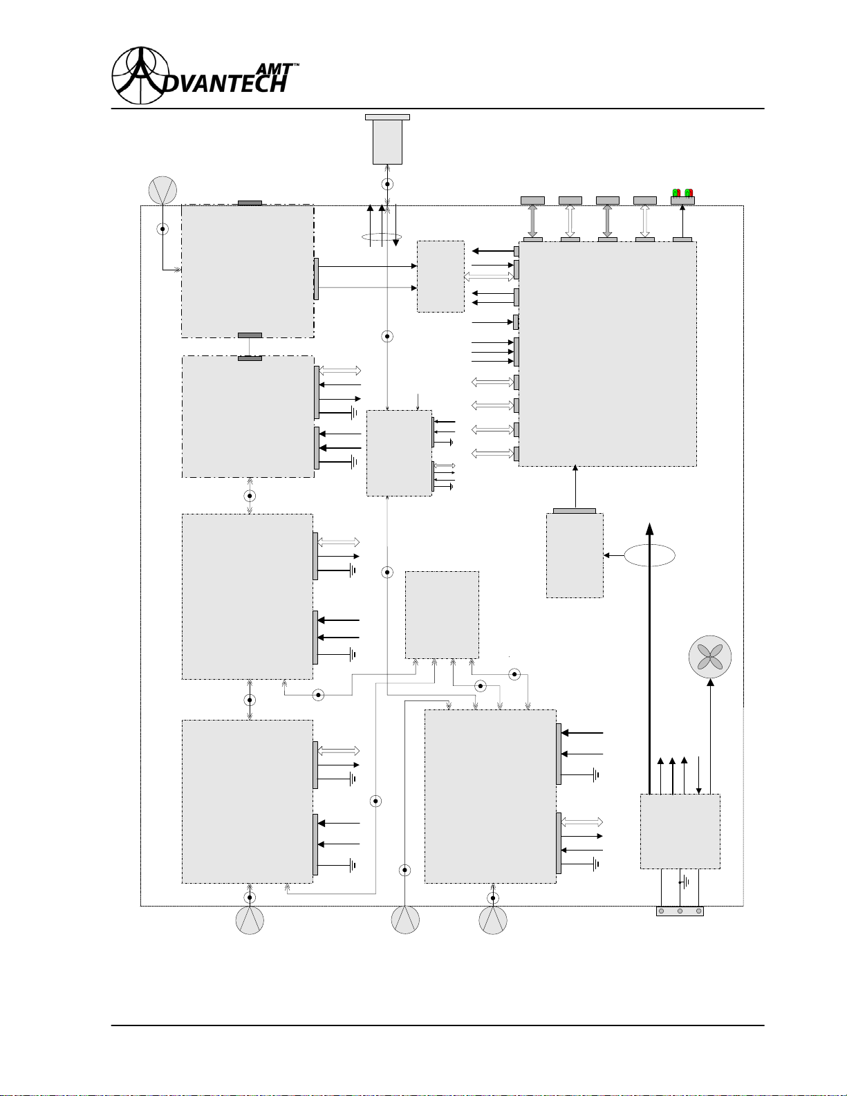
A functional block diagram of a single unit is shown in Figure 3 at page 14.
The AWMT can be combined with a second unit to form a 1:1 redundant system. A redundancy
kit by ADVANTECH AMT™ is available as an option.
4.3 UNIT MAJOR COMPONENTS
The AWMT transceiver consists of the following major components:
• IF to L-Band Up-Converter Module,
• L-Band to RF Up-Converter Module,
• Power Amplifier Module,
• L-Band to IF Down-Converter Module,
• RF-Band Low Noise Block
• Waveguide Assembly,
• 10 MHz Reference Oscillator,
• Main Controller Board,
• Power Supply,
• Current Sensor, and
• Power Monitor Board.
These components are interconnected using dedicated wiring harnesses and coaxial cables. To
clarify the explanation of the components in the following paragraphs, refer to the block diagram
Figure 3 at page 14.
in
11
Page 13
AWMT
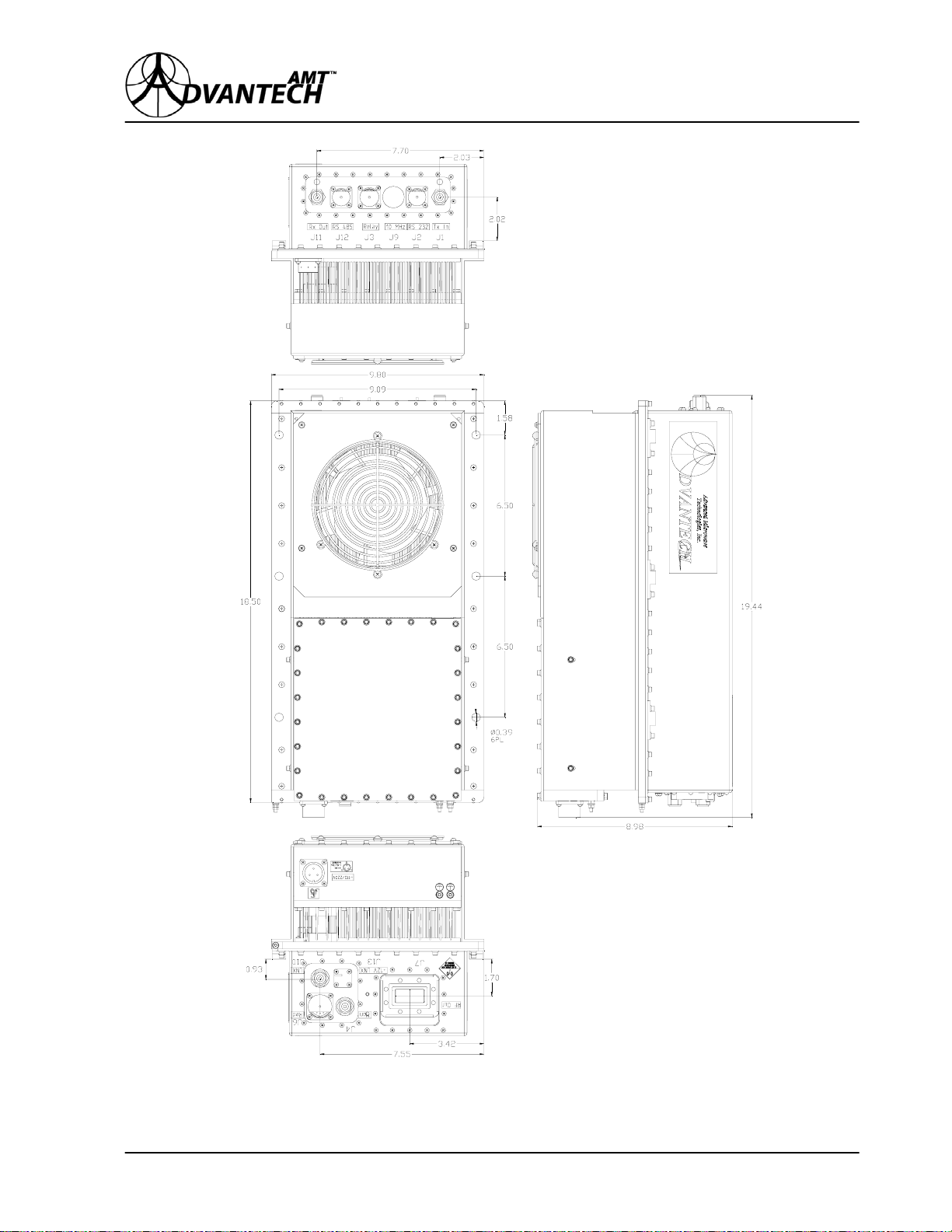
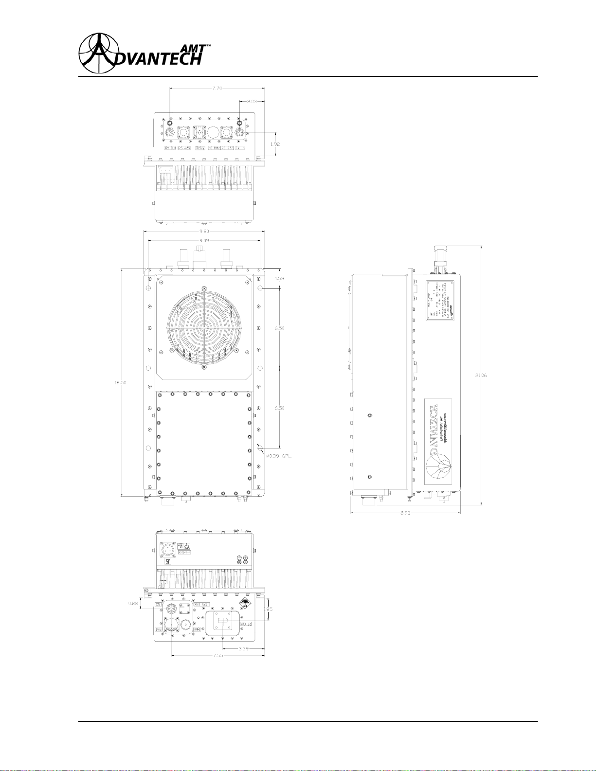
Figure 1: Product Outline (C-Band)
12
Page 14
AWMT
Figure 2: Product Outline (Ku-Band)
13
Page 15
AWMT
LNX
MON
OUTPUT
WR75
TX_OUT
W/G ARM ASSEMBLY
HPA ASSEMBLY
RV_PWR
FW_PWR
RS-485_PA
MUTE_PA
ALM_PA
GND
-9 V
+12 V
GND
RS-485_L-RF
ALM_L-RF
GND
REF
RELAY
Y
A
L
E
R
MAIN CONTROLLER BOARD
RS-232
2
3
2
S
R
RS-485
THERM
CS
MUTE_PA
ALM_L-IF
ALM_L-RF
ALM_PA
ALM_IF-L
RS-485_IF-L
RS-485_PA
RS-485_L-IF
REDUND
REDUND
5
8
4
S
R
CS
CURRENT
SENSOR
RX_IN
+15 V
L-BAND IN
RS-485_PM
POWER
MODULE
MONITOR
MUTE_L-IF
RS-485_L-RF
REF
+12 V
-9 V
GND
RS-485_RF-L
RF TO L-BAND
ALM_RF-L
(optional, for LNA)
MUTE_RF-L
DOWN-CONVER TER
GND
TRANSM
LEDs
RECEIVE
LEDS
+12 V
-9 V
GND
L-BAND TO RF UP-CONVERTER
RS-485_IF-L
ALM_IF-L
GND
+12 V
-9 V
GND
10 MHz
FAN
REFERENCE OSC
COOLING
+ 12 V
LNX_REF
REF
+12 V
-9 V
GND
L-BAND TO IF
DOWN-CONVERTER
RS-485_L-IF
ALM_L-IF
MUTE_L-IF
GND
+ 15 V
- 9 V
+ 5 V
POWER
SUPPLY
0 ... 48V (FAN)
THERM
IF TO L-BAND UP-CONVERTER
LINE
GND
NEUTRAL
J5
A
B
TX_IN
L_OUT
RX_OUT
AC LINE
(or 48 V DC)
C
Figure 3: Block Diagram (Single Unit)
14
Page 16

AWMT
4.3.1 IF TO L-BAND UP-CONVERTER MODULE
The IF/L-Band Up-Converter Module converts and amplifies the incoming IF carrier into
L-Band carrier.
Incorporated into the module is an attenuator with a 20-dB adjustable range. The attenuator is
used to adjust transmit (Tx) gain of the AWMT.
The synthesiser within the module contains an out of lock protection circuitry that prevents the
L-Band carrier from shifting in frequency. When the oscillator is not phase-locked with the
10 MHz reference, an Alarm signal is sent to the main controller board and the up-converter
module will mute automatically.
The operating frequency for the synthesiser and the attenuation are externally controlled by a
serial signal from the main controller board. The transmitting frequency is adjustable in
1 MHz steps.
4.3.2 L-BAND TO RF UP-CONVERTER MODULE
The L/RF Up-Converter Module converts and amplifies the incoming L-Band carrier into the
desired RF-Band carrier.
The synthesiser within the module contains an out of lock protection circuitry that prevents the
L-Band carrier from shifting in frequency. When the oscillator is not phase-locked with the
10 MHz reference, an Alarm signal is sent to the main controller board and the up-converter
module will mute automatically.
4.3.3 L-BAND TO IF DOWN-CONVERTER MODULE
The L/IF-Band Down-Converter Module converts and amplifies the incoming RF signals into
the desired IF frequency range.
Similarly as for the up-converter modules, a 10 MHz high stability reference signal is used to
phase-lock an internal synthesiser.
The operating frequency for the synthesiser and the input attenuation are externally controlled in
the same manner as for the IF/L-Band Up-converter module. The receive (Rx) frequency is
adjustable in 1 MHz steps.
The out of lock protection circuitry within the synthesiser functions similarly as for the
IF/L-Band Up-Converter Module.
The L/IF module provides +12 VDC and the 10 MHz reference to the LNB
15
Page 17

AWMT
4.3.4 POWER AMPLIFIER MODULE
The Power Amplifier Module amplifies the RF signals arriving from the L/RF
up-converter module.
Temperature sensors are installed at the module’s hot spots to prevent the RF devices from
overheating and operating at temperatures exceeding 85ºC.
The power amplifier will be in the Mute mode if the user sends a MUTE command through the
Relay or serial interfaces.
The power amplifier will shut down if the hot spot temperature exceeds +85 °C and any of the
GaAs FET devices fails.
4.3.5 W
AVEGUIDE ASSEMBLY
The Waveguide Assembly contains a forward and reflected power detector, an RF output circulator and the harmonic filters.
The forward power and the reflected power detectors monitor the RF output power level and the
reflected power level respectively. The digital signals are sent to the Main Controller Board.
The circulator provides a VSWR protection at the RF output port. The termination load of the
isolator is capable of fully absorbing any reflected power.
4.3.6 L
OW NOISE BLOCK (LNB)
The LNB functions as a low noise amplifier and a frequency down converter. The RF input
signals are shifted downwards into the L-Band frequency range. Following the conversion the
L-Band signals are amplified to a power level sufficient for transmission into the L-Band to IF
Down-Converter module.
4.3.7 10 MHz R
EFERENCE OSCILLATOR
This module is used to generate a highly stable and very low phase noise 10 MHz reference
frequency with a high stability (of ±5 x 10
-8
MHz/year typical), which is required by all of the
converter modules and the LNB. A 10 MHz reference is sent to each converter module via a
coaxial cable. The oscillator requires approximately 10 minutes to warm up after the transceiver
is power up.
16
Page 18

AWMT
4.3.8 MAIN CONTROLLER BOARD
The Main Controller Board contains a microprocessor controller that performs all of the
monitoring and control, input/output communication and the decision-making. The main
controller board provides:
1. Fault detection and indication from each module of the unit,
2. Mute control and indication (Tx and Rx),
3. Forward RF power indication,
4. Reflected RF power indication,
5. Redundancy control (Tx and Rx),
6. Frequency control (Tx and Rx),
7. Unit Gain control (Tx and Rx), and
8. All interfaces.
4.3.8.1 FAULT Detection and Indication
The Tx path of the unit will automatically go into a shutdown mode and send a message to all of
the external interfaces when any one of the following occurs:
1. The local oscillator within the up-converter module is out of lock.
2. The hotspot temperature exceeds 85°C.
3. Any of the GaAs FET devices failed.
4. Current of +12 VDC supply is out of range.
5. Load VSWR at RF output port (transmit path) exceeds 3.0:1.
The Tx path of the AWMT continually monitors the internal temperature and the current
consumption. It also has an automatic shutdown feature to prevent operation at excessive
temperatures. The unit will automatically restart when the hotspot temperature falls below 65°C.
The Rx path of the unit will automatically go into a shutdown mode and send a message to all of
the external interfaces if:
1. The local oscillator within the L/IF down-converter module is out of lock.
2. The LNX and L/IF down-converter current is out of range
.
4.3.8.2 Tx MUTE Control
The user can remove the RF output power for the Tx path remotely by:
17
Page 19

AWMT
1. Leaving unconnected pins G and H of the Relay interface (see Section 5.1 at page 19).
2. Sending a mute command in terminal mode through the serial interface.
This feature is useful if the user wishes to perform a maintenance check or to check out the
transmission system.
4.3.8.3 Rx MUTE Control
The user can remove the RF output power for the Rx path remotely by:
1. Leaving unconnected pins J and H of the Relay interface (see Section 5.1 at page 19).
2. Sending a mute command in terminal mode through the serial interface.
4.3.9 P
OWER SUPPLY
The Power Supply Module provides +12 VDC, +5 VDC and –9 VDC outputs to all of the
internal modules.
The separate +48 VDC is necessary to operate the cooling fan. The voltage is variable and
temperature dependent that will ensure a variable rotation speed of the cooling fan related to the
temperature (the fan will rotate slower when the temperature is low and faster when the
temperature is high).
The power supply is configured to operate from a 90-138 or 180-264V AC (autoranging),
47-63 Hz, single phase supply, or from 48 V DC (see specifications).
18
Page 20

AWMT
5. INTERFACES
Each transceiver provides five interfaces that can be used to connect the unit to several optional
external devices. The interfaces for this model are listed below:
1. Relay (Discrete) Interface: This interface offers the essential monitoring and control of the
transceiver by the discrete signals.
2. RS-232 Interface: This interface offers the operator essential monitoring and control of the
transceiver using a PC with Term95 or HyperTerminal communications programs.
3. RS-485 Interface: This interface offers the complete monitoring and control of the AWMT
transceiver through the RS-485 serial communication port in packet mode. The system may
be connected to a Monitor & Control Panel or to a Network Manager System (NMS)
4. RF Output Monitor Interface: This interface provides a sample of the output power of the
unit through a 40-dB coupler.
5. Redundancy Interface: The redundant interface provides the communication link between
the two AWMT micro-controllers within a 1:1 redundant system. This interface also
provides control over a redundancy waveguide switch.
6. TX & RX LED’s: green/red LED’s indicating the state of the transmission & receive paths.
• If this LED is not lit, the unit is not powered (or the power supply failed). In redundant
systems, if this LED is not lit it indicates that the unit is in STAND-BY and in MUTE.
• If this LED is RED lit, it indicates that the unit is in FAULT or ALARM condition.
• If this LED is blinking RED, it indicates that the unit is in MUTE state (following a
MUTE command).
• If this LED is GREEN lit, it indicates that the unit is functioning properly. In redundant
system if the LED is GREEN lit indicates that the unit is ON-LINE. If it is blinking
GREEN it indicates that the unit is in STAND-BY and NOT MUTE (RF ON).
5.1 RELAY INTERFACE
The Relay Interface uses a 10-pin circular connector mounted on the transceiver enclosure. The
connector type is listed in TABLE 2 at page 21 and the location is shown in Figure 4 at page 21
and in Figure 5 at page 22. The pin assignment for this interface is shown in TABLE 3 at page
22.
Pins A, B and C of the connector are of Form-C relay type outputs that provide for the user an
indication of informing the status of the transmission path of the AWMT unit.
Pins D, E and F of the connector are of Form-C relay type outputs that provide for the user an
indication of informing the status of the receive path of the AWMT unit.
19
Page 21

AWMT
Pins G and H of the connector are input lines, allowing the user to mute or un-mute the RF
transmit path of the AWMT.
Pins J and H of the connector are input lines, allowing the user to mute or un-mute the RF
receive path of the AWMT.
CAUTION! If pin G is not connected to pin H, the transmission path will remain disabled. If pin
J is not connected to pin H, the receiving path will remain disabled.
20
Page 22

AWMT
TABLE 2: CONNECTORS
Connector Function Description Mating Connector
(J1) Tx In IF Input N - Type (F) N - Type (M)
N – Type (F) Low Power Output N – type (M)
(J7) RF Out RF Output
(J4) Mon RF Output Monitor N - Type (F) N - Type (M)
(J10) LNX
(J11)Rx Out IF Output N - Type (F) N - Type (M)
(J2) RS-232 Serial Interface MS3112E10-6P (M) MS3116F10-6S (F)
(J12) RS 485 Serial Interface MS3112E10-6P (M) MS3116F10-6S (F)
(J3) Relay Discrete Interface MS3112E12-10P (M) MS3116F12-10S (F)
(J6) Red Redundancy Interface MS3112E16-26P (M) MS3116F16-26S (F)
(J5) Line
(J9) 10 MHz
(J13) +12V
LNX
or L OUT
L-Band Input
(from LNB)
AC Line MS3102R16-10P (M) MS3106F16-10S (F)
48 V DC MS3102R10SL-3P (M) MS3106F20-19SX (F)
10 MHz External
Reference (optional)
+12V TO LNX
or L-Band OUT
(optional)
WR 75 (Flat) Ku-Band
High Power Output
CPR 137 (Grooved) C-Band
High Power Output
N - Type (F) N - Type (M)
N - Type (F) N - Type (M)
MS3112E8-3S (F)
or N - Type (F)
WR 75 (grooved)
CPR 137
(Flat or grooved)
MS3116F8-3P (M)
or N - Type (M)
Figure 4: Typical Connector Layout (C-Band)
21
Page 23

AWMT
Figure 5: Typical Connector Layout (Ku-Band)
TABLE 3: RELAY INTERFACE – PIN ASSIGNMENT
Pin Signal Name Description
A Tx AL-NC
B Tx AL-COM Common contact of the Tx ALARM Form - C relay.
C Tx AL-NO
D Rx AL-NC
E Rx AL-COM Common contact of the Rx ALARM Form - C relay.
F Rx AL-NO
G Tx MUTE
H MUTE-COM Common contact of the Tx MUTE and Rx MUTE Commands
J Rx MUTE
K AN_OUT
Normal closed contact of the Tx ALARM Form - C relay.
Pin A closed to pin B indicates ALARM in the transmission path.
Normal open contact of the Tx ALARM Form – C relay.
Pin C open relative to pin B indicates ALARM in the transmission
path.
Normal closed contact of the Rx ALARM Form - C relay.
Pin D closed to pin E indicates ALARM in the receive path.
Normal open contact of the Rx ALARM Form - C relay.
Pin F open relative to pin E indicates ALARM in the receive path.
Tx MUTE command:
If pin G is NOT connected to pin H, the transmission path is in
MUTE. If pin G is connected to pin H, the transmission path is ON.
Rx MUTE command:
If pin J is NOT connected to pin H, the receive path is in MUTE.
If pin J is connected to pin H, the receive path is ON.
Analogue Output - Output Power Monitor (voltage: 5 V DC at rated
P1dB; > 0 V DC at 20 dB back-off)
22
Page 24

AWMT
5.2 RS-232 INTERFACE
This serial communication interface offers to the operator the essential monitoring and control of
the AWMT using any PC terminal software. An IBM compatible personal computer can be
connected to this port. The interface uses a 6-pin circular connector mounted on the AWMT
enclosure. The type of mounting connector is listed in TABLE 2 at page 21 and the location is
shown in Figure 4 at page 21 and in Figure 5 at page 22. The pin assignment for this interface
is shown in TABLE 4 below.
TABLE 4: RS-232 INTERFACE – PIN ASSIGNMENT
Pin Type Signal Name Description
A N/C N/A
B N/C N/A
C Input RX
D Output TX
E DC supply +5V
F Common GND
5.3 RS-485 INTERFACE
This serial communication interface provides access to all monitor and control functions for the
AWMT transceiver.
This interface uses a 6-pin circular connector mounted on the AWMT unit enclosure. The type
of mounting connector is listed TABLE 2 at page 21 and the location is shown in Figure 4 at
21 and in Figure 5 at page 22. The pin assignment for this interface is shown in TABLE 5
page
at page 24.
The RS-485 interface used in a redundant system must be connected to the Network
Management System (NMS). The NMS will have access to both units that discriminates the two
by address.
If this interface is being used, an interconnecting cable with the proper mating connector must be
fabricated.
Not connected
Not connected
Serial receive RX
Serial transmit TX
Power supply for hand held terminal
Serial common
23
Page 25

AWMT
TABLE 5: RS-485 INTERFACE – PIN ASSIGNMENT
Pin Type Signal Name Description
A Output TX+
B Output TXC Input RX+
D Input RX-
E N/C N/A
F Common GND
5.4 REDUNDANT INTERFACE
The Redundant Interface connections are made with a 26-pin circular connector mounted on
the AWMT enclosure. The connector location is shown in Figure 4 at page 21 and in Figure 5
at page 22. A redundant system cable is provided with the redundancy kit that provides the
interconnection between the two AWMT units and the waveguide switches.
5.5 RF OUTPUT MONITOR INTERFACE
This RF output sample port is located at the Mon connector, which is mounted on the AWMT
enclosure. The type of mounting connector is listed in TABLE 2 at page 21 and the location is
shown in Figure 4 at page 21 and in Figure 5 at page 22. This interface is used for the
independent monitoring of the AWMT output before the isolator and the harmonic filter. A table
of the coupling factor versus the frequency is provided with each unit.
Serial transmit TX+
Serial transmit TXSerial receive RX+
Serial transmit RX-
Not connected
Safety ground / Shield
24
Page 26

AWMT
6. UNPACKING AND INSTALLATION
This Section contains instructions for the site preparation, unpacking and the installation of the
AWMT transceiver.
6.1 INITIAL INSPECTION
Inspect the shipping container for damage resulting from the shipment. If damaged, immediately
contact the carrier that delivered the equipment and submit a damage report. Failure to do so
may invalidate future claims.
6.2 UNPACKING
Carefully remove all of the items from the shipping container. Save all of the packing material
until completing successfully the visual inspection. Verify that all of the items listed on the
packing list have been received. If any of the items are missing, contact ADVANTECH AMT™
immediately. Inspect all of the items for evidence of damage resulting from the shipment. If
damage seems evident, immediately contact the carrier that delivered the equipment and file a
claim. Failure to do so may invalidate future claims. Check the AWMT thoroughly for damaged
or loose parts.
6.3 INSTALLATION
Installation of the AWMT requires the following phases:
Relay, Serial Interface and AC (or DC) Power interconnecting cable construction
Environmental and adequate ventilation considerations
Mechanical, RF and electrical installation
TABLE 2 at page 21 lists all of the mounting connectors used by the AWMT unit and their
corresponding mating connectors.
location of the mounting connectors.
6.3.1 RELAY, SERIAL INTERFACES AND AC (OR DC) POWER CABLES CONSTRUCTION
Prior to constructing the interconnecting cables, verify that the all of the cables are of sufficient
length in order to connect the AWMT unit to the user’s remote monitor and control system.
Construct the Relay, RS-232, RS-485 serial interfaces and AC (or DC) Power interconnecting
cables as follows:
Figure 4 at page 21 and in Figure 5 at page 22 show the
25
Page 27

AWMT
1. To use the Relay interface, construct the interconnecting cable using the mating connector
provided in the shipping kit (see TABLE 2 at page 21). Refer to TABLE 3 at page 22 for
the correct pin assignment.
2. To use the RS-232 serial interface, construct an interconnecting cable with a proper mating
connector as given by TABLE 2 at page 21. Refer to TABLE 4 at page 23 for the correct
pin assignment.
3. To use the RS-485 serial interface, construct an interconnecting cable with a proper mating
connector as given by TABLE 2 at page 21. Refer to TABLE 5 at page 24 for the correct
pin assignment.
4. Construct an AC (or DC) power cable with a proper mating connector as given by TABLE 2
at page 21. For the correct pin assignment, refer to TABLE 8 at page 28.
6.3.2 ENVIRONMENTAL AND ADEQUATE VENTILATION CONSIDERATIONS
The AWMT contains a forced air cooling system, which prevents the internal components from
overheating. The cooling subsystem consists of a single fan operating at a variable speed to
effectively distribute and remove the air from within the AWMT unit.
Prior to installing the AWMT, verify that:
1. Environmental conditions listed in TABLE 6 below will be met.
TABLE 6: ENVIRONMENTAL CONDITIONS
Temperature:
Non-operating (continuous exposure)
Operating (ambient)
Relative Humidity: 100% max., condensing, up to 2”/hr rain
Altitude: 10,000’ AMSL, derated 2° C / 1,000’ from AMSL
2. A minimum clearance of 30-cm (12 inches) is necessary in front of the air intake and exhaust
openings on the AWMT mounting-frame.
3. The fan intake grill and the exhaust openings of the AWMT are free of obstructing debris.
CAUTION! Obstructing objects and/or debris may reduce the efficiency of the cooling system
and significantly impact the transceiver longevity.
6.3.3 MECHANICAL, RF AND ELECTRICAL INSTALLATION
1. Bolt the AWMT on to the antenna hub by using the six mounting holes provided by the
enclosure, see Figure 1 at page 12 and Figure 2 at page 13.
2. For AWMT units equipped with a waveguide flange at the RF output port:
- 50° C to + 85° C
- 30° C to + 55° C
26
Page 28

AWMT
a. Position the interconnecting waveguide system flange so that it aligns precisely with the
flange of the RF output port.
b. Install the supplied waterproof gasket (supplied in the packing list) on to the
interconnecting waveguide flange.
CAUTION: To protect the inside pressure window installed by ADVANTECH AMT™, do not
pressurise the waveguide interior above 2-3 psi of pressure.
c. After alignment verification, loosely attach the interconnecting waveguide on to the RF
output port using the hardware provided in the shipping kit.
d. Carefully tighten all bolts (in opposite pairs rather than sequentially around the perimeter
of the flange) so that the connection is firm.
CAUTION! Do not over-tighten the waveguide flange screws. Over-tightening the screws may
cause the stripping of the threads or distort the mating flange. The recommended
torque is 30 in-lbs for the screws.
7. For AWMT units equipped with an N type female connector at the RF output port, connect to
the port a transmission line equipped with an N type male connector.
4. Ground the AWMT by attaching a #6 gauge copper wire to the ground terminal provided by
the unit enclosure and to a properly grounded structure.
5. To use the Relay interface, attach the interconnecting cable fabricated per Section 6.3.1 at
page 25 to the Relay connector of the AWMT. Connect the free end of the interconnecting
cable to the operator’s monitor and control system.
NOTE: Whether this interface is being used or not, it is necessary to connect pin G of the
Relay connector to pin H (common) in order to enable (un-mute) the transmission
path. If pin G of this interface is not connected to pin H, the transmission path of
the unit will remain muted. Also it is necessary to connect pin J of the Relay
connector to pin H (common) in order to enable (un-mute) the receiving path. If
pin J of this interface is not connected to pin H, the receiving path of the unit will
remain muted.
6. To use the RS-485 interface, connect the interconnecting cable fabricated per Section 6.3.1 at
page 25 to the RS-485 port of the AWMT.
7. To use the RS-232 interface, then:
a. Connect the interconnecting cable fabricated per Section
port of the AWMT.
6.3.1 at page 25 to the RS-232
b. Attach to the free end of the interconnecting cable a 9-pin or 25-pin D-type connector
with a pin assignment as listed in TABLE 7 at page 28.
c. Attach the cable with the 9-pin or 25-pin D-type connector to RS-232 port of a personal
computer.
27
Page 29

AWMT
TABLE 7: SERIAL INTERFACE RS-232 CONNECTION INFORMATION
Serial Interface
RS-232 Pin
C
D
E +5 VDC power source
F Common
8. Connect the IF input source to the N-type female connector at the Tx In input port.
9. Verify that AC (or DC) power source is switched OFF.
10. Verify that the AC (or DC) power source can satisfy the power requirements given by the
AWMT specifications.
WARNING! Proper grounding of the AC (or DC) power outlet is necessary for personnel
and equipment safety. Improper grounding may cause serious injury or
death of the operator.
11. Using the AC (or DC) power cable fabricated per Section 6.3.1 at page 25, connect one end
of the power cable to port (J5) of the AWMT.
Active Condition
RX Í 3
TX Î 2
RS-232 at PC Pin
DB-9 DB-25
2
3
-
5
7
CAUTION! Ensure that the proper pin is selected for AC (or DC) operation. Applying power on
the wrong pin may permanently damage the AWMT necessitating factory repair.
Refer to TABLE 8 below for the correct pin assignment.
12. Connect the remaining end of the cable to the AC (or DC) power source.
TABLE 8: LINE (J5) CONNECTOR – PIN ASSIGNMENT
Description
Units with DC Supply Units with AC Supply
+48 V DC Phase (live) A
Ground Ground B
48 V RETURN Neutral C
13. If necessary, connect a power meter or a spectral analyser to the RF output monitor port
(Mon).
Pin
28
Page 30

AWMT
7. PRE-POWER AND SYSTEM CHECKOUT
This Section describes the pre-power procedure for the AWMT.
WARNING! The information presented in this Section is addressed to technicians who
have specific training in, and knowledge of Microwave Power Transceivers.
Inappropriate use of the AWMT may cause serious injury to the operator or
may result in damage of the unit. Do not attempt to operate the AWMT
before becoming thoroughly familiar with the contents in this Section.
NOTE: When prime power is ON, the main controller board will start operating!
7.1 PRE-POWER PROCEDURES
Before applying power to the AWMT, verify that the following conditions are met:
7. Verify that the voltage of the station’s AC (or DC) prime power matches with the value
marked on the ID label.
8. The prime power station is properly grounded.
9. All cable and waveguide connections are secure and there is no evidence of pinched wires
and loose hardware.
10. The circuit breaker at the prime power station is switched OFF.
11. The IF input and RF output ports are connected to a matched source and a proper load
capable of withstanding full CW RF power.
12. The cooling fan is unobstructed.
7.2 OPERATIONAL SETTINGS VERIFICATION
The AWMT arrives with all of its factory-pre-set operational values that meet the requirements
of a typical installation. Before starting the unit at the installation site, check the configurable
settings and if necessary, reset to meet the customer’s requirements.
29
Page 31

AWMT
8. OPERATION
8.1 INTRODUCTION
This Section describes the normal operation of the AWMT. The design of this equipment allows
for minimal operator intervention and maintenance.
The AWMT may be monitored and controlled via the serial interfaces, or the Relay interface.
The Relay interface provides for the user an alarm indication and remote RF mute capability of
the designated AWMT unit. The RS-232 and the RS-485 serial interfaces provide access to the
AWMT functions, including the monitoring of key operating parameters, gain control (in both
transmission and receive paths), transmission/receive frequency control and shutdown.
8.2 SAFETY CONSIDERATIONS
WARNING! Prolonged operation without a load at the output may cause severe bodily
harm, loss of sight and even death. Do not operate the transceiver if the RF
output connector is not connected to a load.
Please note that an AWMT failure due to the above condition will be attributed to abuse or
neglect and will not be covered by the standard warranty.
8.3 BASIC OPERATING PROCEDURE
Perform the following operating procedure:
1. Verify that the ‘Pre-Power and System Checkout’ procedure as described in Section 7 at
page 29 was performed successfully.
2. Switch ON the main power source.
3. Allow at least ten seconds for the software to boot into the PC.
4. If using either the RS-232 or the RS-485 interface, set up the serial communication linkage
between the AWMT and the user’s computer terminal. See Section
8.5 at page 33. Press t2
(command to switch to PC Terminal) and <ENTER> in Term95 or HyperTerminal
communications program.
30
Page 32

t
j
AWMT
CAUTION: The unit will always start in RF ON (NOT MUTE) state, provided the correc
connections are installed at the Relay Interface. In order to set the unit functional, connect the
umpers on the Relay Interface between pins G and H (to un-mute the transmission path) and
between pins J and H (to un-mute the receive path).
5. Ensure that the IF input signal is being applied to the Tx In port of the AWMT.
6. Adjust the frequencies of the transmission and receive paths in MHz.
7. Adjust the gain of the transmission and receive paths.
8. Allow the AWMT to warm up for 30 minutes, ensuring that all of the electrical specifications
are met.
31
Page 33

AWMT
8.4 AUTOMATIC LEVEL CONTROL (ALC)
The unit has Automatic Level Control feature (ALC) that will keep the Tx output level at a
previously set value. Normally the unit should work with 10 dB less gain (set by operator) than the
maximum gain, in ALC mode and at an output power 3 to 15 dB back-off from P1dB. The 10 dB
less gain set is necessary as a reserve, in order to allow the ALC system to ensure a constant output
power in case the input power dropped.
The output power is monitored via an output power detector that sends to the Monitor & Control
Board an analogue voltage signal proportional with the actual output power. This signal is
converted into a digital value and stored in a calibration table putting in correspondence digital
values with actual output power levels. After a certain output power is set (by setting a certain gain
level to the unit) the M&C is able to maintain this set output power level by increasing or
decreasing the attenuation command signal that is sent to the attenuator for gain control. An ALC
control loop is so created ensuring the maintaining of the output power at the set level when the
input power varies.
The ALC command may be followed by a value of the needed output power level and in this case
the target power will be set to that value. If the ALC command is not followed by any value, the
current value of the output power level will be considered as target value.
Note that if the ALC feature is ON, the gain control is not available for the operator.
The ALC “high” alarm is issued when the input power is too high and the attenuation reached the
maximum allowable value (the attenuator cannot ensure enough attenuation of the input power).
The ALC “low” alarm is issued when the input power is too low and the attenuation reached the
minimum allowable value (even with 0 dB attenuation, at maximum gain set, the input power level
is too low for maintaining the target output level).
Up-CONVERTER
GAIN CONTROL
AMPLIFIER
MONITOR
AND
CONTROL
ALC LOOP
30 dB
OUTPUT
POWER
DETECTOR
32
Page 34

AWMT
8.5 USING THE AWMT SOFTWARE
The RS-232 and the RS-485 interfaces provide the serial communication between the user’s
monitoring and control system and the micro-controller within the AWMT. The user may
employ any RS-232 terminal communications software (Term95, HyperTerminal or equivalent)
or the RS-485 serial communication protocol.
8.5.1 USING THE RS-232 INTERFACE
Before using the RS-232 Interface, become thoroughly familiar with the items listed in
TABLE 9 at page 35 and TABLE 10 at page 37.
Operate the AWMT via the RS-232 Interface as follows:
1. Switch on the power station’s circuit breaker to power up the AWMT.
2. Run any terminal program in the personal computer.
3. Use the following communication parameters:
- Bits per second: 19200
- Data Bits: 8
- Parity: None
- Stop bits: 1
- Flow Control: None
4. After running the program in the computer and pressing the <ENTER> key a display similar
to Figure 6 below will be shown.
NOTE: The micro-controller determines automatically whether the unit is functioning
alone or in a 1:1 redundant system.
5. If necessary, to change the status of the AWMT, use the commands listed in
page
37.
TABLE 10 at
NOTE: At start up the AWMT is in the hand-held Terminal Mode. To change to PC
Mode, type ‘t2’ and then press <ENTER>. For operation with the Hand Held
Terminal type ‘t1’.
If the Hand Held Terminal model 8045 is used for the RS-232 communication with the unit, the
adequate configuration should be set. In order to set the configuration:
- While simultaneously pressing the CTRL, SHIFT keys press the F1 key.
- In the menu displayed use F1 key to change parameters, F2 & F3 keys to navigate, F4
key to quit (without changing parameters) and F5 key to save the changed values for
parameters. Type again F4 to exit the menu. The required values for parameters are:
- BAUD RATE: 19200
- DATA BITS: 8
- PARITY: NONE
- STOP BITS: 1
33
Page 35

AWMT
Figure 6: RS-232 Terminal Mode Display
34
Page 36

AWMT
TABLE 9: RS-232 MENU ITEM DEFINITION
Item Description
S/N
Soft
Unit Pos
Name
MAC
Current
TxF
TxF Shift
FPWR
TxGain
Tx Stat
RPWR
RxF
RxF Shift
Rx Level
AWMT serial number
Version number of the main controller software within the AWMT.
Indicates the position of the unit A or B. (1:1 redundant system only).
Indicates the name of the AWMT.
Indicates the serial address of the AWMT main controller (in hex).
Indicates the 12 VDC current consumption of the AWMT, in amperes.
Indicates the transmission frequency of the AWMT in MHz.
Indicates the local oscillator frequency of the transceiver transmission path in
MHz.
Indicates the forward power of the transceiver (transmission path output
power) in dBm.
Indicates the transmission Gain in dB.
Indicates the transmission status (On or Mute).
Indicates the reverse (reflected) power of the transceiver (the transmission
path reflected power) in dBm.
Indicates the receive frequency of the transceiver in MHz.
Indicates the local oscillator frequency of the transceiver receive path in MHz.
Indicates the receive path output power level (not available for the unit).
RxGain
Rx Stat
LNx Curr
Temp HS
PS
Elaps Time
Alarms
Ref
Indicates the receive gain in dB
Indicates the receive status (On or Mute)
Indicates the current consumption of the Low Noise Block Down Converter
(LNB) in amperes.
Hot spot temperature of the unit in degrees Celsius.
Power Supply DC Voltage
Elapsed Time from the first start-up of the unit (days:hours)
Provides the alarm and fault messages and the normal status message:
1. Alarm (excess +12 VDC current, faulty RF devices, power supply failure,
IF-L or L-RF up-converter modules failure, L-IF down-converter module
failure, low power alarm, high power alarm).
2. Temperature Pre-Alarm (hot spot temperature exceeds 75 ºC)
3. Out of Lock of the PLL in IF-L or L-RF up-converter modules, or in L-IF
down-converter module triggering a shutdown
4. High Reflected Power shutdown
5. Overdrive Alarm (output power exceeds by 1.5 dB the rated P1dB)
6. Temperature shutdown (hot spot temperature exceeds 85ºC)
7. OK (AWMT transceiver is functioning properly).
Reference (internal or external)
35
Page 37

AWMT
Figure 7: List of commands (after pressing h- Help) in Terminal Mode Display
36
Page 38

AWMT
TABLE 10: COMPUTER TERMINAL COMMANDS FOR RS-232 INTERFACE
Command Description Response
h Help function
<ENTER>
ENTER key of
keyboard
txo Tx PLL stat
rxo Rx PLL stat
tmp Temperature
nam Set unit name
txf Set Tx freq
txg Set Tx gain
tsw Tx Switch
txm Tx Mute
txu Tx Unmute
tme Time(h:m:s)
dat Date(d:m:y)
rxf Set Rx freq
rxg Set Rx gain
snb Serial number
mac MAC address
cur Consumption
alm Alarms
sst
psn
rxm
rxu
Status
Unit position
Rx Mute
Rx Unmute
Provides the list of commands that can be used to modify the status of
the AWMT.
Provides and refreshes the main menu display on the computer
monitor screen.
The status of the transmission PLL will be displayed.
The status of the receive PLL will be displayed.
The hot spot temperature of the AWMT will be displayed.
Allows for a name to be attributed to the AWMT.
Allows for the adjustment of the transmission frequency of the
AWMT, in MHz.
Allows for the adjustment of the transmission gain of the AWMT in
dB. (Tx gain range: 51 to 71 dB)
Allows for the switching of the transmission from one unit to the other
(redundant system only).
Transmission Mute command. The transmission path of the AWMT
is muted. (no RF output power)
Transmission un-mute command. The transmission path of the
AWMT is enabled.
Current time will be displayed.
(in format hour : minutes : seconds)
Current date will be displayed.
(in format day : month : year)
Allows for the adjustment of the receiving frequency of the AWMT in
MHz.
Allows for the adjustment of the receiving gain of the AWMT in dB.
(Rx gain range 60 to 80 dB)
Displays the serial number of the AWMT.
Displays the main controller address.
Displays the DC current consumption of the AWMT.
Displays the ALARMS of the AWMT.
(OK if no alarm)
Displays the system status.
(redundant system only)
Displays the position of the AWMT in the redundant system. (A or B,
redundant system only)
Receiving Mute command. The receive path of the AWMT is muted.
(no IF output power).
Receiving un-mute command. The receive path of the AWMT is
enabled.
37
Page 39

AWMT
TABLE 10: COMPUTER TERMINAL COMMANDS FOR RS-232 INTERFACE
Command Description Response
fpw Forward PW
rpw Reflected PW
rsw Rx Switch
lnx LNX Current
t1 Hand held
t2 PC term
rfs Rx freq shift
tfs Tx freq shift
dnl download
lng LNB Gain Set
stc
lnr
lnv
ssw
Tx Start
LNB Reference
LNX Voltage
Simultaneous
switching
Displays the forward transmission output power in dBm.
Displays the reflected transmission power in dBm.
Allows for the switching of the receiving from one unit to the other
(redundant system only).
Displays the current consumption of the LNx in mA.
Selects the hand-held Terminal Mode.
Selects the PC Terminal Mode.
Displays the frequency of the receiving path Local Oscillator.
Displays the frequency of the transmission path Local Oscillator.
Allows the AWMT to go into the download mode.
The gain read on the LNB is supplied to the system, in order to compute the
overall Rx Gain.
Start condition of Tx (on, mute, or previous state)
Status of LNB Reference (on, off)
Status of voltage sent to LNX (on, off)
Simultaneous switching of Tx and Rx (in redundant systems) – on, off
tml
rml
ver
rdt
rdr
tll
elt
alc
fss
Tx L-Band Signal
Level
Tx MUTE logic
Rx MUTE logic
Elapsed Time
Software Version
Automatic Level
Control
Frequency Step
Size
Set Redundancy
transmission
Set Redundancy
receive
L-Band transmission signal, in dBm
Set Tx MUTE logic (normal, reverse). In normal logic, the unit is mute if the
strap on Relay Interface is not installed.
Set Rx MUTE logic (normal, reverse). In normal logic, the unit is mute if the
strap on Relay Interface is not installed.
Elapsed time from first start-up of the unit is displayed (days:hours)
Indicates the software version downloaded in the unit
Set ALC (on, off, <pwr>)
Set frequency control step size (1MHz, 125 kHz)
Set redundancy for transmission
Set redundancy for receive
38
Page 40

AWMT
8.5.1.1 Downloading the Customer Supplied Software
If it is required to change the internal software features, then download the supplied software as
follows:
1. Create a new folder in the hard drive of a PC.
2. From the supplied source, copy the file “dlapp2000.exe” and the file with extension “.hex”
into this folder.
3. Make R2-232 connection between PC and the unit.
4. Disconnect redundancy cable from unit (in case of a redundancy system).
5. Run the terminal mode program provided by the PC.
6. Run the “big terminal” mode (command “t2”).
7. From the terminal mode type “dnl” command and press <Enter>.
The message “Enter <yes> to confirm download” appears on the display.
CAUTION: Typing <yes> for download will cause the contents in the non-volatile
memory to be cleared. If the user desires to retain the contents in the non-volatile memory,
any other key may be pressed.
8. Follow the screen instructions to set download mode.
9. After several seconds, the LED on the unit will flash red-green and the message “Ready for
download from RS232” after typing <yes>.
From this moment, the memory of the unit is cleared! It is necessary to download the
application!
10. Close the terminal mode program.
11. Open the new folder and start the dlapp2000.exe program.
The DLAPP2 display with instructions appears on the screen.
12. At the prompt type “s[space]comX” and then press <Enter>.
NOTE: X is the number of the communication port connected to the unit.
13. At the prompt type “pl[space] 19200 and then press <Enter>.
14. At the prompt type “l[space] filename.hex” and then press <Enter>.
15. After 20–30 seconds the download process should start. You will see progress on the screen.
16. When loading is complete, press ”q” and <Enter> to close “dlapp2000”.
17. Go to the terminal and check unit’s settings.
If download process was interrupted, it is need to restart power of the unit and start download
process again without items from 6 to 9.
39
Page 41

AWMT
8.5.2 USING THE RS-485 INTERFACE
In order to use this interface, refer to Section 10 APPENDIX A: RS-485 SERIAL
COMMUNICATION PROTOCOL at page 42.
40
Page 42

AWMT
9. MAINTENANCE
This Section describes the scheduled maintenance procedure for the AWMT.
CAUTION! Improper maintenance of the AWMT may void the warranty.
9.1 PREVENTIVE MAINTENANCE
This product requires minimal maintenance, which consists of visual inspection and cleaning.
WARNING! The person performing maintenance of this equipment must have training
and knowledge of both the product and the safety requirements and issues
related to the equipment. Read and practice the safety guidelines in
Section 1 at page 6.
9.2 MECHANICAL PREVENTIVE MAINTENANCE
Mechanical preventive maintenance consists of verifying the condition of all mechanical parts,
with the AC (or DC) power switched off. Perform the following inspection:
1. Check all connectors and plugs for evidence of damage and improper seating. Replace
defective connector plugs and reset any that are dislodged.
2. Inspect the electrical wiring for signs of discoloured, broken or poor insulation. Repair or
replace if necessary.
3. Inspect all waveguides for discoloration, cracks, loose connectors and improper sealing.
Tighten or replace waveguides as required.
4. Check for other defects such as, wear, breakage, deterioration, fungus, excess moisture and
mounting integrity.
9.3 COOLING FAN CHECK
The AWMT is forced-air cooled, using a single fan. The cooling fan is located at the bottom
shroud. Verify that the fan is operating smoothly. Any suspect noise may indicate a worn fan
that must be replaced. Check for debris or dust in the fan intake and in all openings on the unit.
This may reduce the efficiency of the cooling system. The fan should be replaced every two
years, in order to ensure the proper cooling of the AWMT.
WARNING! Do not come in contact with any electrical assembly while power is applied.
41
Page 43

AWMT
10. APPENDIX A: RS-485 SERIAL COMMUNICATION PROTOCOL
The protocol described in this Section is used for the interconnection between the AWMT and
the user’s monitoring and control system. The protocol supports the 4-wire RS-485 interface
using the communication set-up 9600.N.8.1.
10.1 FRAME STRUCTURE
Each frame starts from start byte – 0x55
After this start byte, each frame consists of 7 bytes described as follows:
• First byte master–slave – address of the correspondent unit (0x01 to 0x07, address 0x00 –
will be used as broadcast address and must be used only for commands.
• First byte slave-master – address of the unit, shifted to the left by 4 (e.g. for a unit with
address 0x05, the returned address is 0x50).
• Second byte master-slave – command or data request.
• Third, forth and fifth bytes master-slave – value of parameter or expansion of command:
third byte – MS byte, forth byte – LS byte, fifth byte – value after decimal point.
• From second to sixth bytes slave-master – data or status from slave.
• Seventh byte master-slave and slave-master - check sum, calculated as algebraic sum of bytes
1-6.
NOTE: Format for gain, level, current consumption and temperature is a 2-byte
hexadecimal value in 0.1 dB, 0.1 dBm, 0.1 A or 0.1 degree (signed integer).
Format for the LNX current is a 2-byte hexadecimal value in 1 mA steps
(unsigned integer).
Format for frequency is a 2-byte hexadecimal value in 1 MHz steps (unsigned
integer). All unused bytes are always - 0xAA.
10.2 COMMANDS
TABLE 11 at page 43 lists all of the commands that go in the master-slave direction.
NOTE: If slave does not recognise the command from the master, the response of the
slave is given in TABLE 12 at page 44.
42
Page 44

AWMT
TABLE 11: COMMAND TO TRANSCEIVER
No Description
1. Request condition status
2. Mute/Unmute command 0x02
3. Read RF frequency set 0x0F
4. Set RF frequency 0x04
5. Read identification 0x07
6. Read serial number 0x08
7. Read gain set 0x0A
8. Set gain 0x05
2nd
byte
0x01
or
0x2A
3, 4, 5 & 6 bytes
0xAA, 0xAA, 0xAA,
0xAA
0x5A – mute Tx
0xA5 – unmute Tx
0x0F – mute Rx
0xF0 – unmute Rx
0x5A for Tx
0xA5 for Rx
0x5A XX XX XX for Tx
0xA5 XX XX XX for Rx
0xAA, 0xAA, 0xAA,
0xAA
0xAA, 0xAA, 0xAA,
0xAA
0x5A for Tx
0xA5 for Rx
0x5A XX XX XX for Tx
0xA5 XX XX XX for Rx
Response: 2, 3, 4, 5 & 6
bytes
TABLE 12
See
No answer
See TABLE 14
No Response
See TABLE 13
5 ASCII characters
2 &3 &4 bytes – real gain
No Response
9. Read temperature 0x12
10. LNX current 0x13
11.
12.
13.
Read unit and switch
position and status
Switch WG switches
(redundant system only)
Read forward and reflected
power levels
0x23
0x24
0x25
0xAA, 0xAA, 0xAA,
0xAA
0xAA, 0xAA, 0xAA,
0xAA
0xAA, 0xAA, 0xAA,
0xAA
0x5A – Tx
0xA5 - Rx
0x5A – Tx
0xA5 - Rx
2, 3 bytes -temperature
2,3 bytes –LNX current
See TABLE 15
No Response
2-3 bytes: FWD
5-6 bytes: REV
43
Page 45

AWMT
10.3 RESPONSE TO COMMANDS FROM SLAVE TO MASTER
For command 1 (request condition status) the response is given in the following table.
TABLE 12: CONDITION STATUS RESPONSE
Bit
No
4-th byte – Internal Communication Status is:
2nd byte 3rd byte 4th byte 5th byte 6th byte
0 Tx status 1-on, 0-off Rx status 1-on, 0-off
1 1- Tx PLL Alarm 1-Rx PLL Alarm
2
3 1-Alarm
4 N/A
5 N/A
6 N/A
7
Output
level
MS byte
1 – for no communication, 0 – for communication O/K.
Bit 7 Bit 6 Bit 5 Bit 4 Bit 3 Bit 2 Bit 1 Bit 0
N/A N/A
Output
level
LS byte
Module
Internal
Communication
Status
L-IF
RF-L
Module
1- Check sum error
in command
Power Class for
P1dB
(power in dBW)
5 bits
From 30dBm – step
1dB
0 dBW = 30 dBm
1 dBW = 31 dBm
…
20 dBW = 50 dBm
PA
Module
IF-L
Module
1- Unknown
command
N/A
L-RF
Module
PM
Module
44
Page 46

AWMT
TABLE 13: READ IDENTIFICATION RESPONSE
Bit
No
0 1 – Up
1 1 – Down
2 1 – PA 0
3 0 0
4 0 0
5 0 0
6 0 0
7 0 0
2nd byte 3rd byte 4th byte 5th byte 6th byte
1- Rx spectrum inv
0- not Rx spectrum inv
1 – ALC On
0 – ALC Off
TABLE 14: READ FREQUENCY SET RESPONSE
Bit
No
0
1
2
3
4
5
6
7
2nd byte 3rd byte 4th byte 5th byte 6th byte
MS byte
Frequency
LS byte
Frequency
0x00 – N/A
0x01 – 70 to L
0x02 – 70 to C
0x03 – 70 to Ku
0x04 – 140 to L
0x05 – 140 to C
0x06 – 140 to Ku
0x07 – L to C
0x08 – L to Ku
0x5A for Tx
0xA5 for Rx
Value after
decimal point
0xAA
Software
version
number
0xXX
0xAA
45
Page 47

AWMT
TABLE 15: UNIT STATUS AND SWITCH POSITION RESPONSE
Bit
No
0 1–B; 0-A
1
2
3
4
5
6
7 0 0 0 0 0
2nd byte 3rd byte 4th byte 5th byte 6th byte
Tx 1-unmute;
0-mute
Rx 1-unmute;
0-mute
Tx 1- on line
0 – S/B
Rx 1- on line
0 - S/B
1 – Standalone
0 - Redundant
1 – Unit
position error
1- Tx alarm;
0-Tx O/K
1-IF-L alarm 1-L-IF alarm
1-L-RF alarm 1-RF–L alarm 0
1-PA temper
alarm
1-PA devices
alarm
0 0 0 0
0 0 0 0
1- Rx alarm;
0-Rx O/K
1- LNX
current alarm
0 0 0
1- Consumption
current alarm
1- Reflected
power alarm
0
1-Tx W/G
switch alarm
1-Rx W/G
switch alarm
1 – Tx W/G
switch not
connected
1 – Rx W/G
switch not
connected
46
Page 48

AWMT
11. APPENDIX B: SAFETY AND EMC COMPLIANCE
ADVANTECH AMT™ products are compliant with following standards:
SAFETY: IEC 60950-1 second edition 2005
EMC: EN301489-1 2004 (EMC for radio equipment and services, common technical
requirements):
EN 55022: 1998 / A1: 2000 - Class A
EN61000-4-4 Transient/burst 0.5kV Signal Lines, 1 kV Power Lines
EN61000-4-2 Electrostatic discharge 4kV CD, 8 kV AD
EN61000-4-5 Surge 1kV, 0.5 kV
EN61000-4-11 AC port dips 70%, 40%, 0%
EN 61000-4-3 Radiated Immunity 80-1000 MHz @ 3 V/m
SUPPLEMENTARY INFORMATION:
The products herewith comply with the requirements of the Low Voltage Directive 73/23/EEC
and of the EMC Directive 89/336/EEC and may carry the CE-marking accordingly.
47
Page 49

AWMT
12. ANNEX C: SPECIFICATIONS FOR 250 W C-BAND TRANSCEIVERS MODEL AWMT -C250-DRE (P/N 1T0-11G1 10-6B0)
The Transceivers specified herein are capable of meeting or exceeding the performance
specifications listed in the following table over frequency range, operating temperature and line
voltage variation, unless otherwise specified. The units will meet all RF performance specifications
within thirty minutes of application of prime power.
Transmitter
TABLE 16: TRANSMITTER SPECIFICATIONS
Specification Conditions Value/Limits
Tx Output Frequency
Range
Tx Frequency Step
Adjustment
Tuning Range 5.850 to 6.425 GHz
By software 1 MHz
Tx Signal Bandwidth ±18 MHz
Tx Output Power P1dB 53 dBm (250 W saturated power)
Tx Gain Linear mode 74 dB, typ at maximum set gain
Tx Gain Adjustment By software 20 dB, (between 54 and 74 dB, typical)
TX Gain Adjustment Step 1 dB
Tx Third Order
Intermodulation
Tx Output VSWR CPR-137 G 1.22:1 max (-20 dB, max Return Loss)
Tx Gain Flatness Over any 36 MHz 3.0 dB p-p, max
Tx Gain Variation with
temperature
Tx Input Frequency 70 MHz ± 18 MHz
Tx Input Power
two equal tones, 5 MHz
apart
Linear mode
- 25 dBc, max @ 3 dB back-off total power
3 dB from –30 °C to +55 °C
±1 dB for ±10 °C
–20 dBm, for reaching P1dB @ maximum
gain set
Tx Input VSWR 70 MHz 1.29:1 max
Tx Input Impedance
N-type connector 50 Ω 50 Ω
48
Page 50

AWMT
Receiver
TABLE 17: RECEIVER SPECIFICATIONS
Specification Conditions Value/Limits
Rx Input Frequency Range 3.400 to 4.200 GHz
Rx Input Noise Temperature
Rx Frequency Adjustment Step 1 MHz
Rx Signal Range ±18 MHz
Rx Gain Linear mode 80 dB, typ at maximum set gain
Rx Gain Adjustment By software 20 dB
Rx Gain Adjustment Step 1 dB
Rx input VSWR
Rx output frequency 70 ±18 MHz
Rx output VSWR 1.25:1
Rx output level P1dB
Rx Output Impedance
With TRF & Isolator
(provided by customer)
70 MHz ± 18 MHz
N-type connector 50 Ω 50 Ω
35 °K typical
1.25:1
0 dBm, typ
49
Page 51

AWMT
TABLE 18: MECHANICAL SPECIFICATIONS
Physical Dimensions See Figure 8: Product Outline (C-Band 250W) at page 51
and Figure 9: Connector Layout (C-Band 250W) at page 52
Approximate Weight 62 lbs (28 kg)
Mounting Requirements See Figure 8: Product Outline (C-Band 250W) at page 51
Figure 9: Connector Layout (C-Band 250W) at page 52
and
TABLE 19: POWER REQUIREMENTS
Power Requirements 48 V DC
Power Consumption 26 A typical @ 48 V DC, 1250W (each unit)
50
Page 52

AWMT
Figure 8: Product Outline (C-Band 250W) – DC Line (48 V) Unit
51
Page 53

AWMT
Figure 9: Connector Layout (C-Band 250W) – DC Line (48 V) Unit
52
Page 54

AWMT
Figure 10: Product Outline (Ku-Band Low Power)
53
Page 55

AWMT
Figure 11: Typical Connector Layout (Ku-Band Low Power)
54
Page 56

AWMT
Figure 12: Product Outline (Redundant System, Ku-Band Low Power)
55
Page 57

AWMT
Figure 13: Product Outline Side View (Redundant System, Ku-Band Low Power)
56
Page 58

AWMT
Figure 14: Mounting of a Low Power Transceiver on Feed Support
57
Page 59

AWMT
Figure 15: Outline Drawing of C-Band Light Weight 60W C-Band Transceiver
58
Page 60

AWMT
Figure 16: Connectors of Light Weight 60W C-Band Transceiver
59
Page 61

AWMT
Figure 17: Outline Drawing of C-Band 10W C-Band Transceiver
60
Page 62

AWMT
Figure 18: Connectors of 10W C-Band Transceiver
61
Page 63

AWMT
Figure 19: Proposed GUI for RS-485 Communication (transceiver single unit)
62
Page 64

AWMT
Figure 20: RS-232 Terminal Mode Display for Redundant System
63
Page 65

AWMT
Figure 21: Proposed GUI for RS-485 Communication (transceiver redundant system)
64
 Loading...