

Page 1

User Manual
ARK-2250
Fanless Embedded Box
Computer
Page 2

Attention!
Please note:
This package contains a hard-copy user manual in Chinese for China CCC certifica-
tion purposes, and there is an English user manual included as a PDF file on the
website. Please disregard the Chinese hard copy user manual if the product is not to
be sold and/or installed in China.
Notez s'il vous plaît:
Ce package contient un manuel de l'utilisateur sur papier en chinois à des fins de
certification Chine CCC, et il existe un manuel de l'utilisateur en anglais non inclus
sous forme de fichier PDF sur le site Web. Veuillez ne pas tenir compte du manuel de
l'utilisateur sur papier chinois si le produit ne doit pas être vendu et / ou installé en
Chine.
ARK-2250 User Manual ii
Page 3

Copyright
The documentation and the software included with this product are copyrighted 2021
by Advantech Co., Ltd. All rights are reserved. Advantech Co., Ltd. reserves the right
to make improvements in the products described in this manual at any time without
notice.
No part of this manual may be reproduced, copied, translated or transmitted in any
form or by any means without the prior written permission of Advantech Co., Ltd.
Information provided in this manual is intended to be accurate and reliable. However,
Advantech Co., Ltd. assumes no responsibility for its use, nor for any infringements
of the rights of third parties, which may result from its use.
Acknowledgments
Award is a trademark of Award Software International, Inc.
VIA is a trademark of VIA Technologies, Inc.
IBM, PC/AT, PS/2 and VGA are trademarks of International Business Machines Cor-
poration.
Intel® and Pentium® are trademarks of Intel Corporation.
Microsoft Windows® is a registered trademark of Microsoft Corp.
RTL is a trademark of Realtek Semi-Conductor Co., Ltd.
ESS is a trademark of ESS Technology, Inc.
UMC is a trademark of United Microelectronics Corporation.
SMI is a trademark of Silicon Motion, Inc.
Creative is a trademark of Creative Technology LTD.
CHRONTEL is a trademark of Chrontel Inc.
All other product names or trademarks are properties of their respective owners.
For more information about this and other Advantech products, please visit our website at:
http://www.advantech.com/
http://www.advantech.com/ePlatform/
For technical support and service, please visit our support website at:
http://support.advantech.com.tw/support/
Part No. 2006K22502 Edition 3
February 2021
iii ARK-2250 User Manual
Page 4

Product Warranty (2 years)
Advantech warrants to you, the original purchaser, that each of its products will be
free from defects in materials and workmanship for two years from the date of purchase.
This warranty does not apply to any products which have been repaired or altered by
persons other than repair personnel authorized by Advantech, or which have been
subject to misuse, abuse, accident or improper installation. Advantech assumes no
liability under the terms of this warranty as a consequence of such events.
Because of Advantech’s high quality-control standards and rigorous testing, most of
our customers never need to use our repair service. If an Advantech product is defective, it will be repaired or replaced at no charge during the warranty period. For outof-warranty repairs, you will be billed according to the cost of replacement materials,
service time and freight. Please consult your dealer for more details.
If you think you have a defective product, follow these steps:
1. Collect all the information about the problem encountered. (For example, CPU
speed, Advantech products used, other hardware and software used, etc.) Note
anything abnormal and list any onscreen messages you get when the problem
occurs.
2. Call your dealer and describe the problem. Please have your manual, product,
and any helpful information readily available.
3. If your product is diagnosed as defective, obtain a return merchandise authori-
zation (RMA) number from your dealer. This allows us to process your return
more quickly.
4. Carefully pack the defective product, a fully-completed Repair and Replacement
Order Card and a photocopy proof of purchase date (such as your sales receipt)
in a shippable container. A product returned without proof of the purchase date
is not eligible for warranty service.
5. Write the RMA number visibly on the outside of the package and ship it prepaid
to your dealer.
Declaration of Conformity
FCC Class B
Note: This equipment has been tested and found to comply with the limits for a Class
B digital device, pursuant to part 15 of the FCC Rules. These limits are designed to
provide reasonable protection against harmful interference in a residential installation. This equipment generates, uses and can radiate radio frequency energy and, if
not installed and used in accordance with the instructions, may cause harmful interference to radio communications. However, there is no guarantee that interference
will not occur in a particular installation. If this equipment does cause harmful interference to radio or television reception, which can be determined by turning the equipment off and on, the user is encouraged to try to correct the interference by one or
more of the following measures:
Reorient or relocate the receiving antenna
Increase the separation between the equipment and receiver
Connect the equipment into an outlet on a circuit different from that to which the
receiver is connected
Consult the dealer or an experienced radio/TV technician for help
ARK-2250 User Manual iv
Page 5
Technical Support and Assistance
1. Visit the Advantech web site at www.advantech.com/support where you can find
the latest information about the product.
2. Contact your distributor, sales representative, or Advantech's customer service
center for technical support if you need additional assistance. Please have the
following information ready before you call:
– Product name and serial number
– Description of your peripheral attachments
– Description of your software (operating system, version, application software,
etc.)
– A complete description of the problem
– The exact wording of any error messages
Warnings, Cautions, and Notes
Warning! Warnings indicate conditions, which if not observed, can cause personal
injury!
Caution! Cautions are included to help you avoid damaging hardware or losing
data.
There is a danger of a new battery exploding if it is incorrectly installed.
Do not attempt to recharge, force open, or heat the battery. Replace the
battery only with the same or equivalent type recommended by the manufacturer. Discard used batteries according to the manufacturer's
instructions.
Note! Notes provide optional additional information.
Warning! Les avertissements indiquent des conditions qui, si elles ne sont pas
respectées, peuvent provoquer des blessures!
Caution! Des précautions sont incluses pour vous aider à éviter d'endommager le
matériel ou de perdre des données.
Il y a un risque d'explosion d'une nouvelle batterie si elle n'est pas
installée correctement. N'essayez pas de recharger, d'ouvrir de force ou
de chauffer la batterie. Remplacez la batterie uniquement par un type
identique ou équivalent recommandé par le fabricant. Jetez les piles
usagées conformément aux instructions du fabricant.
Note! Les notes fournissent des informations supplémentaires facultatives.
v ARK-2250 User Manual
Page 6

Packing List
Before installation, please ensure the following items have been shipped:
1 x ARK-2250 unit
1 x China RoHS
1 x Simplified Chinese manual
Ordering Information
Model Number Description
ARK-2250L-U6A2 ARK-2250L Intel® Core™ i7-6600U 2.6GHz system
ARK-2250L-U3A2 ARK-2250L Intel® Core™ i3-6100U 2.3GHz system
ARK-2250L-U8A2 ARK-2250L Intel® Core™ i7-7600U
ARK-2250L-U4A2 ARK-2250L Intel® Core™ -3-7100U
Optional Accessories
For ARK-2250
Part Number Description
96PSA-A60W12W7-3 AC-to-DC Adapter, DC12V/5A 60W with lockable DC jack
MOS-1120Y-0201E Isolated RS-232, 2-Ch, DB9
MOS-1120Y-1401E Non-Isolated RS-232, DB37, 4-Ch
MOS-1121Y-0201E Isolated RS-422/485, 2-Ch, DB9
MOS-1121Y-1401E Non-Isolated RS-422/485, DB37, 4-Ch
MOS-2120-Z1101E Giga LAN Ethernet module, 1-Ch
MOS-2220-X1101E Parallel LPT module, 1-Ch, USB I/F
MOS-1130Y-0201E Isolated CANBus, 2-Ch, DB9, PCIe I/F
MOS-2230-Z1201E CANBus module, 2-Ch, USB I/F
MOS-1110Y-0101E Isolated 16 DI/8 DO, 1-Ch, DB37, PCIe I/F
MIOE-PWR2-00A1E 9~36V DC-in power module
96PSA-A65W19P2-1 AC-to-DC Adapter, DC19V/3.42A 65W (for MIOe-PWR2)
AMO-2201E 4 x RS232/422/485+ removable 2.5" drive (2nd layer)
AMO-2203E 2 x isolated CAN-Bus (2nd layer)
AMO-2204E 3 x GbE + iDoor (2nd layer, this iDoor support USB I/F only)
ARK-2250 User Manual vi
Page 7

Safety Instructions
1. Please read these safety instructions carefully.
2. Please keep this User Manual for later reference.
3. Please disconnect this equipment from AC outlet before cleaning. Use a damp
cloth. Don’t use liquid or sprayed detergent for cleaning. Use a moist sheet or
clothe for cleaning.
4. For pluggable equipment, the socket-outlet should be near the equipment and
should be easily accessible.
5. Protect this equipment from humidity.
6. Lay this equipment on a reliable surface when installing. A drop or fall could
cause injury.
7. The openings on the enclosure are for air convection and protecting the equip-
ment from overheating. DO NOT COVER THE OPENINGS.
8. Make sure the voltage of the power source when connecting the equipment to
the power outlet. The power outlet socket should have ground connection.
9. Place the power cord such a way that people cannot step on it. Do not place
anything over the power cord.
10. All cautions and warnings on the equipment should be noted.
11. If the equipment is not used for long time, disconnect the equipment from mains
to avoid being damaged by transient over-voltage.
12. Never pour any liquid into ventilation openings; this could cause fire or electrical
shock.
13. Never open the equipment. For safety reasons, only qualified service personnel
should open the equipment.
14. If one of the following situations arises, get the equipment checked by service
personnel:
The power cord or plug is damaged
Liquid has penetrated into the equipment
The equipment has been exposed to moisture
The equipment does not work well, or you cannot get it to work according to
the user manual
The equipment has been dropped and damaged
The equipment has obvious signs of breakage
15. Do not leave this equipment in an environment where the storage temperature
may go below -40 °C (-40 °F) or above 85 °C (185 °F). This could damage the
equipment. the equipment should be in a controlled environment.
16. Caution: Danger of explosion if battery is incorrectly replaced. Replace only with
the same or equivalent type recommended by the manufacturer, discard used
batteries according to the manufacturer's instructions.
17. The sound pressure level at the operator's position according to IEC 704-1:1982
is no more than 70 dB (A).
18. RESTRICTED ACCESS AREA: The equipment should only be installed in a
Restricted Access Area.
19. DISCLAIMER: This set of instructions is given according to IEC 704-1. Advant-
ech disclaims all responsibility for the accuracy of any statements contained
herein.
20. The product is to be connected only to PoE networks without routing to the out-
side plant.
21. The product is intended to be supplied by an Listed power supply or dc ES1,
rated 12Vdc, 5A/12Vdc, 10A/9-36Vdc, 8-2A to match the unit rating, if need further assistance, please contact Advantech for further information.
vii ARK-2250 User Manual
Page 8

Safety Instructions
1. Veuillez lire attentivement ces consignes de sécurité.
2. Veuillez conserver ce manuel d'utilisation pour référence ultérieure.
3. Veuillez déconnecter cet équipement de la prise secteur avant de le nettoyer.
Utilisez un chiffon humide. N'utilisez pas de détergent liquide ou pulvérisé pour
le nettoyage. Utilisez une feuille d'humidité ou des vêtements pour le nettoyage.
4. Pour les équipements enfichables, la prise de courant doit être proche de l'équi-
pement et doit être facilement accessible.
5. Veuillez garder cet équipement à l'abri de l'humidité.
6. Posez cet équipement sur une surface fiable lors de l'installation. Une chute ou
une chute pourrait provoquer des blessures.
7. Les ouvertures sur l'enceinte sont destinées à la convection d'air, protégeant
ainsi l'équipement de la surchauffe. NE COUVREZ PAS LES OUVERTURES.
8. Assurez-vous de la tension de la source d'alimentation lorsque vous connectez
l'équipement à la prise de courant. La prise de courant doit avoir une connexion
à la terre.
9. Placez le cordon d'alimentation de manière à ce que personne ne puisse
marcher dessus. Ne placez rien sur le cordon d'alimentation.
10. Toutes les précautions et avertissements sur l'équipement doivent être notés.
11. Si l'équipement n'est pas utilisé pendant une longue période, débranchez-le du
secteur pour éviter d'être endommagé par une surtension transitoire.
12. Ne versez jamais de liquide dans les ouvertures de ventilation; cela pourrait pro-
voquer un incendie ou un choc électrique.
13. N'ouvrez jamais l'équipement. Pour des raisons de sécurité, seul un technicien
qualifié doit ouvrir l'équipement.
14. Si l'une des situations suivantes se présente, faites vérifier l'équipement par le
personnel de service:
– Le cordon d'alimentation ou la fiche est endommagé.
– Du liquide a pénétré dans l'équipement.
– L'équipement a été exposé à l'humidité.
– L'équipement ne fonctionne pas bien, ou vous ne pouvez pas le faire
fonctionner selon le manuel de l'utilisateur.
– L'équipement est tombé et a été endommagé.
– L'équipement présente des signes évidents de rupture.
15. Ne laissez pas cet équipement dans un environnement où la température de
stockage peut être inférieure à -40 ° C (-40 °F) ou supérieure à 85 °C (185 °F).
Cela pourrait endommager l'équipement. l'équipement doit se trouver dans un
environnement contrôlé.
16. Attention: risque d'explosion si la batterie n'est pas remplacée correctement.
Remplacez uniquement par un type identique ou équivalent recommandé par le
fabricant, jetez les piles usagées conformément aux instructions du fabricant.
17. Le niveau de pression acoustique au poste de l'opérateur selon CEI 704-1:
1982 n'est pas supérieur à 70 dB (A).
18. ZONE D'ACCÈS RESTREINT: l'équipement ne doit être installé que dans une
zone d'accès restreint.
19. AVIS DE NON-RESPONSABILITÉ: Cet ensemble d'instructions est donné con-
formément à la CEI 704-1. Advantech décline toute responsabilité quant à
l'exactitude des déclarations contenues dans le présent document.
20. Le produit doit être connecté uniquement aux réseaux PoE sans acheminement
vers l'installation extérieure.
ARK-2250 User Manual viii
Page 9

21. Le produit est destiné à être alimenté par un bloc d'alimentation homologué ou
dc ES1, évalué à 12Vdc, 5A / 12Vdc, 10A / 9-36Vdc, 8-2A pour correspondre à
la puissance nominale de l'unité.Si besoin d'assistance supplémentaire, veuillez
contacter Advantech pour plus d'informations.
ix ARK-2250 User Manual
Page 10

ARK-2250 User Manual x
Page 11

Contents
Chapter 1 General Introduction ...........................1
1.1 Introduction ............................................................................................... 2
1.2 Product Features....................................................................................... 3
1.2.1 General ......................................................................................... 3
1.2.2 Display .......................................................................................... 3
1.2.3 Ethernet ........................................................................................3
1.3 Chipset...................................................................................................... 4
1.3.1 Functional Specification................................................................ 4
1.3.2 WISE-PaSS/RMM......................................................................... 5
1.4 Mechanical Specifications......................................................................... 5
1.4.1 Dimensions ................................................................................... 5
Figure 1.1 ARK-2250 Mechanical dimension drawing................. 5
1.4.2 Weight........................................................................................... 5
1.5 Power Requirement .................................................................................. 5
1.5.1 System Power............................................................................... 5
1.5.2 RTC Battery .................................................................................. 5
1.6 Environment Specification......................................................................... 6
1.6.1 Operating Temperature................................................................. 6
1.6.2 Relative Humidity.......................................................................... 6
1.6.3 Storage Temperature.................................................................... 6
1.6.4 Vibration during Operation............................................................ 6
1.6.5 Shock during Operation ................................................................ 6
1.6.6 Safety............................................................................................ 6
1.6.7 EMC.............................................................................................. 6
Chapter 2 H/W Installation....................................7
2.1 Introduction ............................................................................................... 8
2.2 Jumpers .................................................................................................... 8
2.2.1 Jumper Description....................................................................... 8
2.2.2 Jumper List ...................................................................................9
Table 2.1: Jumper setting ............................................................ 9
2.2.3 Jumper Location ........................................................................... 9
Figure 2.1 Jumper Layout............................................................ 9
2.2.4 Jumper Setting.............................................................................. 9
2.3 Connectors.............................................................................................. 10
2.3.1 ARK-2250 External I/O ............................................................... 10
Figure 2.2 ARK-2250 IO ............................................................ 10
Figure 2.3 Power On/Off Button ................................................11
Figure 2.4 LED........................................................................... 11
Figure 2.5 HDMI Connector....................................................... 11
Figure 2.6 VGA Connector ........................................................12
Figure 2.7 USB 3.0 Connector................................................... 12
Figure 2.8 USB 2.0 Connector................................................... 13
Figure 2.9 Ethernet Connector (LAN)........................................ 13
Figure 2.10Audio Connector....................................................... 14
Figure 2.11GPIO Connector ....................................................... 15
2.4 Installation............................................................................................... 15
2.4.1 Memory Installation..................................................................... 15
2.4.2 HDD/SSD Installation.................................................................. 16
2.4.3 mSATA Installation .....................................................................18
2.4.4 Power Module (MIOe-PWR2) Installation (Option)..................... 19
2.4.5 iDoor Module Installation (Option) .............................................. 22
2.4.6 2nd Layer MIOe Module Installation (Option) ............................. 22
xi ARK-2250 User Manual
Page 12

2.4.7 Wall Mount Installation (Option).................................................. 22
Chapter 3 BIOS Settings .................................... 23
3.1 Entering Setup ........................................................................................ 24
3.2 Main ........................................................................................................ 24
3.3 Advanced................................................................................................ 26
3.3.1 ACPI Settings ............................................................................. 27
3.3.2 AMT Configuration...................................................................... 28
3.3.3 PCH-FW Configuration............................................................... 29
3.3.4 Embedded Controller Configuration ........................................... 30
3.3.5 Trusted Computing ..................................................................... 31
3.3.6 S5 RTC Wake Settings............................................................... 31
3.3.7 Serial Port Console Redirection.................................................. 32
3.3.8 CPU Configuration...................................................................... 33
3.3.9 Intel TXT Information .................................................................. 35
3.3.10 Platform Misc Configuration........................................................ 36
3.3.11 SATA Configuration .................................................................... 37
3.3.12 Network Stack Configuration ...................................................... 39
3.3.13 CSM Configuration ..................................................................... 40
3.3.14 USB Configuration ...................................................................... 41
3.3.15 First Super IO Configuration ....................................................... 42
3.4 Chipset.................................................................................................... 44
3.4.1 System Agent Configuration....................................................... 45
3.4.2 PCH-IO Configuration................................................................. 49
3.5 Security Setup......................................................................................... 54
3.6 Boot Settings........................................................................................... 55
3.7 Save & Exit ............................................................................................. 56
Appendix A Watchdog Timer Sample Code ........ 57
A.1 EC Watchdog Timer sample code .......................................................... 58
ARK-2250 User Manual xii
Page 13

Chapter 1
1 General Introduction
This chapter gives background
information on the ARK-2250
series.
Page 14

1.1 Introduction
ARK-2250 is an intelligent, modular, and fanless embedded system. A fully modular
design, ARK-2250 supports easy I/O switching with optional iDoor modules, wide
range power board, and MIOe board expansions. ARK-2250 is aimed at factory automation, machine automation, kiosks, and self-service applications.
Rugged, Multi-functional Design
ARK-2250 embedded box PC is powered by an Intel 6th gen core i3/i7 processor.
The compact size system provides a selection of I/O ports: 4 x USB 3.0, 2 x USB 2.0,
2 x GbE, 4 x COM, 2 x mPCIe and 1 x 2.5" HDD. The default power input is 12V DC
in, and it also supports an optional wide range 9~36V power module with wide temperature operation of -20 to 60C. ARK-2250 passes worldwide certification including
CE/FCC, CB, UL, CCC and BSMI.
Multiple Display Support
ARK-2250 supports up to 3 display types: VGA, HDMI as the default display, and an
expansion display module. It can also provide DP, HDMI, DVI-D as a 3rd optional display port. The graphic engine is DirectX 11.3, OpenGL 4.4, and OpenCL 2.1 Full
AVC/VC1/MPEG2 HW Decode.
Built-in Intelligent Management Tools — WISE-PaSS/RMM
Advantech WISE-PaSS/RMM provides a valuable suite of programmable APIs such
as multi-level watchdog, hardware monitor, system restore, and other user-friendly
interface. iManager is an intelligent self-management cross platform tool that monitors system status for problems and takes action if anything is abnormal. It offers a
boot up guarantee in critical, low temperature environments so systems can automatically recover when voltages dip. WISE-PaSS/RMM makes the whole system more
reliable and more intelligent. ARK-2250L provides easy remote management so
users can monitor, configure, and control a large number of terminals to make maintenance and system recovery simpler.
ARK-2250 User Manual 2
Page 15

1.2 Product Features
1.2.1 General
CPU:
6th Gen. Intel® Core™ i7-6600U processor 2.6GHz
6th Gen. Intel® Core™ i3-6100U processor 2.3GHz
7th Gen. Intel® Core™ i7-7600U processor 2.8GHz
7th Gen. Intel® Core™ i3-7100U processor 2.4GHz
BIOS: AMI UEFI 128Mbit
System Memory: 1x DDR4 2133 MHz up to 16 GB
Watchdog Timer: Single chip Watchdog 255-level interval timer, setup by soft-
ware
I/O Interface: 4 x RS232/422/485
USB: 2 x USB 2.0, 4 x USB 3.0 compliant ports
Audio: High Definition Audio (HD), Line out, Mic-in
Storage: 1 x mSATA and 1 x high capacity 2.5” SATA HDD (up to 12.5 mm/.49
in) height
Expansion Interface:
– Supports 2 x MiniPCIe (1 with SIM holder)
– Supports 1 x iDoor expansion (by 1st layer)
– Supports 1 x ARK Plus expansion (by 2nd layer)
Chapter 1 General Introduction
1.2.2 Display
Controller: Intel® HD Graphics 520
Resolution:
– VGA: Supports up to 1920 x 1200
– HDMI: Supports up to 4096 x 2160 @ 24Hz
Dual Display: VGA+HDMI
Triple Display: VGA+HDMI+3rd optional display
1.2.3 Ethernet
Chipset:
– LAN1 Intel i219
– LAN2 Intel i210
Speed: 1000 Mbps
Interface: 2 x RJ45
Standard: Compliant with IEEE 802.3, IEEE 802.3u, IEEE 802.3x, IEEE 802.3y,
IEEE 802.ab.
3 ARK-2250 User Manual
Page 16

1.3 Chipset
1.3.1 Functional Specification
1.3.1.1 Processor
6th Gen. Intel® Core™ i7-6600U processor 2.6GHz
Processor
Memory
1.3.1.2 Chipset
6th Gen. Intel® Core™ i3-6100U processor 2.3GHz
7th Gen. Intel® Core™ i7-7600U processor 2.8GHz
7th Gen. Intel® Core™ i3-7100U processor 2.4GHz
Supports DDR4 2133 MHz up to 16GB
1 x 260-pin SODIMM socket type
Internal Graphics Features
Video Accelerator
SATA Interface
USB Interface
BIOS UEFI 128Mbit
1.3.1.3 Others
Serial ports
DirectX 11.3, OpenGL 4.4
Display Ports VGA + HDMI, HDMI 1.4a
H/W accelerated video decode
Video decoder: AVC/VC1/MPEG2 HW Decode
Supports DVD, Blu-ray, and HD video
Supports several optional sections of Serial ATA II: Extensions to
Serial ATA 1.0 Specification, Revision 1.0
Supports SATA transfers to 300 Mbytes/sec.
Supports mSATA socket
USB host interface with support for 4 x USB 3.0 and 2 x USB 2.0
ports
All ports are High-Speed, Full-Speed, and Low-Speed capable
Supports legacy keyboard/mouse software
COM1 ~ COM4: Supports RS-232/422/485 and change mode under
BIOS setting
** COM1 ~ COM4 RS-485 supports auto-flow control.
COM connector: D-SUB CON. 9P
LAN1 Intel i219, LAN2 Intel i210
Compliant with IEEE 802.3, IEEE 802.3u, IEEE 802.3x, IEEE 802.3y,
Ethernet
Audio
Battery backup BATTERY 3V/210 mAh with WIRE x 1
ARK-2250 User Manual 4
IEEE 802.ab.
Supports 10/100/1000 Mbps.
LAN Connectors: Phone Jack RJ45 8P 90D(F)
Audio Codec: Realtek ALC888S:
Compliant with HD Audio specifications
Supports 16/20/24-bit DAC and 16/20/24-bit ADC resolution
Supports: Line-out, Mic-in
Audio Connectors: Ear Phone Jack * 2
Page 17
1.3.2 WISE-PaSS/RMM
Sequence control Supported
Watchdog timer Multi Level WDT
Programmable 1-255 sec / min
Hardware monitor CPU Temperature / input Current / input Voltage
Power saving Deep sleep S5 mode
System information Running HR / Boot record
1.4 Mechanical Specifications
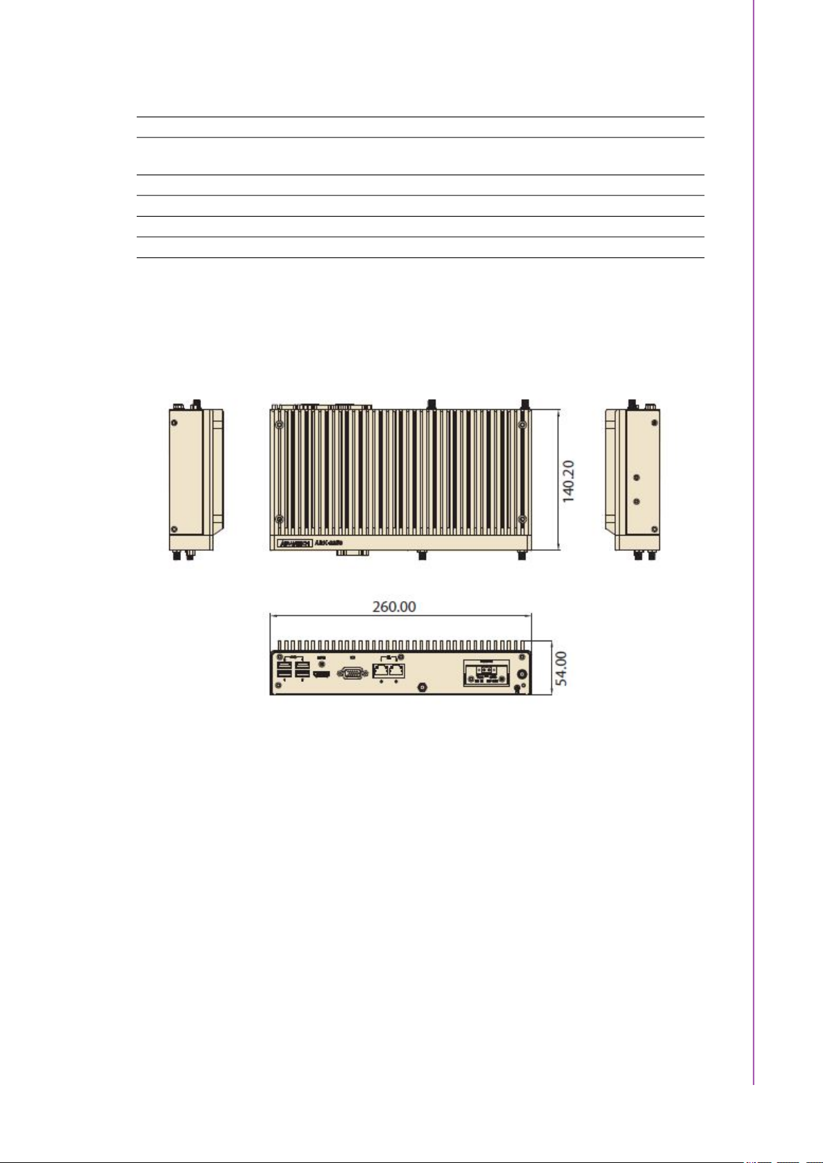
1.4.1 Dimensions
Unit: mm / in: 260 x 54 x 140.2 mm / 10.24 x 2.13 x 5.52 in
Chapter 1 General Introduction
Figure 1.1 ARK-2250 Mechanical Dimension Diagram
1.4.2 Weight
2.3 kg (5.06 lb)
1.5 Power Requirements
1.5.1 System Power
Minimum power input:
– ARK-2250: DC 12V, 5A
1.5.2 RTC Battery
Lithium 3 V/210 mAH
5 ARK-2250 User Manual
Page 18

1.6 Environment Specification
1.6.1 Operating Temperature
With Industrial Grade SSD/mSATA: -20 ~ 60 °C (-4 ~ 140° F), with air flow,
speed = 0.7 m/sec (for single layer)
With 2.5 inch hard disk: 0 ~ 40 °C (32 ~ 104 °F), with air flow, speed = 0.7 m/sec
(for single layer and dual layer)
With Industrial Grade SSD/mSATA: 0 ~ 40 °C (32 ~ 104 °F), with air flow, speed
= 0.7 m/sec (for dual layer)
1.6.2 Relative Humidity
95% @ 40 °C/104 °F (non-condensing)
1.6.3 Storage Temperature
-40 ~ 85 °C (-40 ~ 185 °F)
1.6.4 Vibration During Operation
When the system is equipped with SSD/mSATA: 3Grms, IEC 60068-2-64, ran-
dom, 5 ~ 500 Hz, 1hr/axis, x,y,z 3 axes.
1.6.5 Shock During Operation
When the system is equipped with SSD/mSATA: 30G, IEC 60068-2-27, half
sine, 11 ms duration.
1.6.6 Safety
UL, CB, CCC, BSMI
1.6.7 EMC
CE, FCC, CCC, BSMI
ARK-2250 User Manual 6
Page 19

Chapter 2
2 H/W Installation
This chapter introduces external I/
O and hardware installation for
ARK-2250.
Page 20
2.1 Introduction
closed 2-3closedopen
12 12
closed 2-3closedopen
The following sections detail the internal jumpers settings and the external connector
pin assignments for different applications.
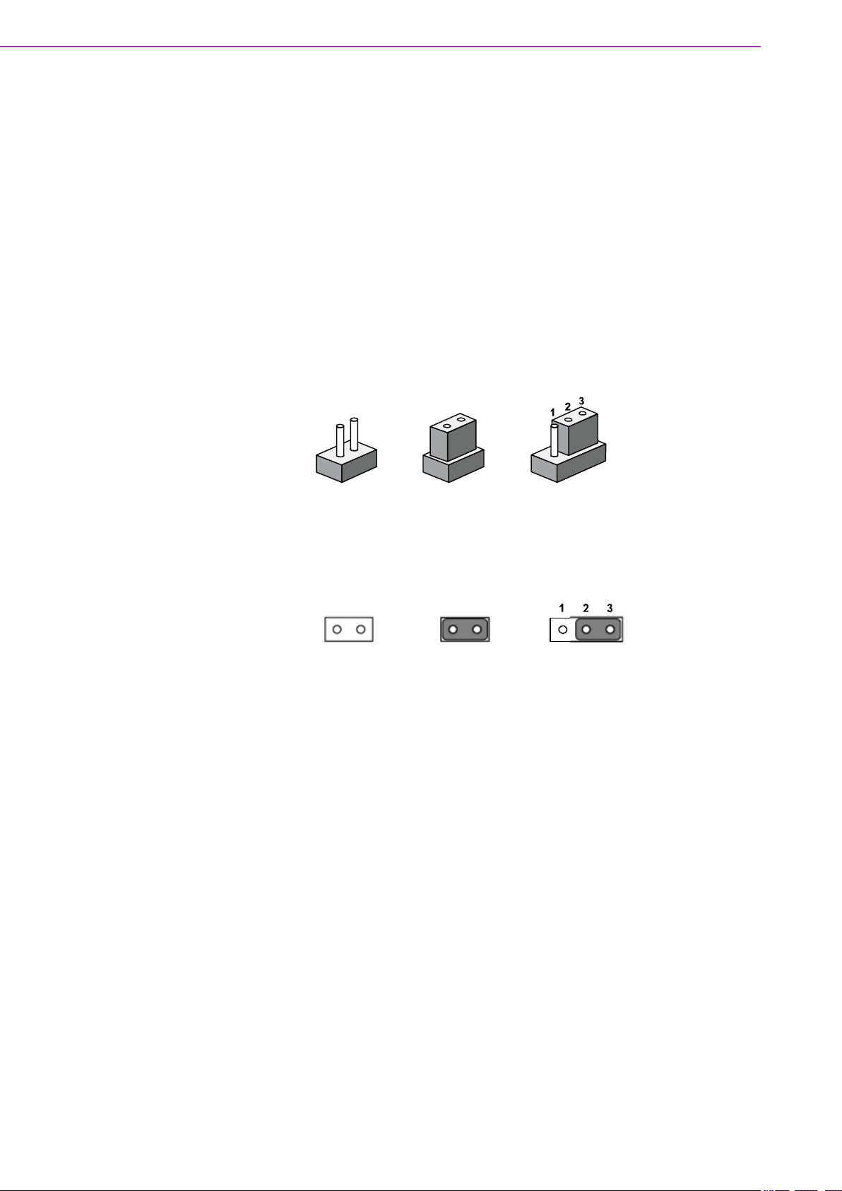
2.2 Jumpers
2.2.1 Jumper Description
You may configure ARK-2250 to match the needs of your application by setting jumpers. A jumper is a metal bridge used to close an electric circuit. It consists of two
metal pins and a small metal clip (often protected by a plastic cover) that slides over
the pins to connect them. To close a jumper, you connect the pins with the clip. To
open a jumper, you remove the clip. Sometimes a jumper will have three pins,
labeled 1, 2 and 3. In this case you would connect either pins 1 and 2, or 2 and 3.
The jumper settings are schematically depicted in this manual as follows.
A pair of needle-nose pliers may be helpful when working with jumpers. If you have
any doubts about the best hardware configuration for your application, contact your
local distributor or sales representative before you make any changes. Generally, you
simply need a standard cable to make most connections.
ARK-2250 User Manual 8
Page 21
2.2.2 Jumper List
Table 2.1: Jumper Settings
J1 Auto Power On Setting
SW2 RTC Reset
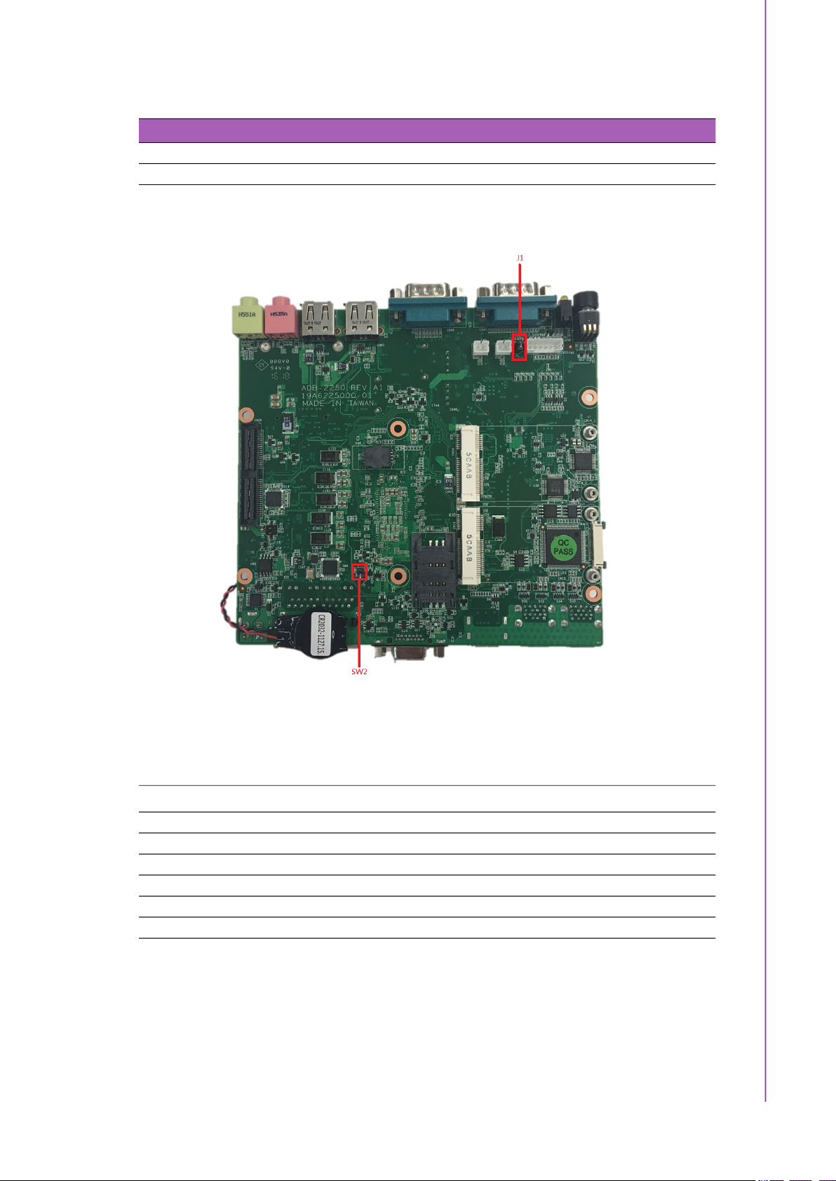
2.2.3 Jumper Location
Chapter 2 H/W Installation
2.2.4 Jumper Settings
On the Motherboard
J1 Auto Power On Setting
Part Number 1653002101
Footprint HD_2x1P_79_D
Description PIN HEADER 2*1P 180D(M)SQUARE 2.0mm DIP W/O Pb
Setting Function
NL Power On by power button (default)
(1-2)* Auto Power On
Figure 2.1 Jumper Layout
9 ARK-2250 User Manual
Page 22
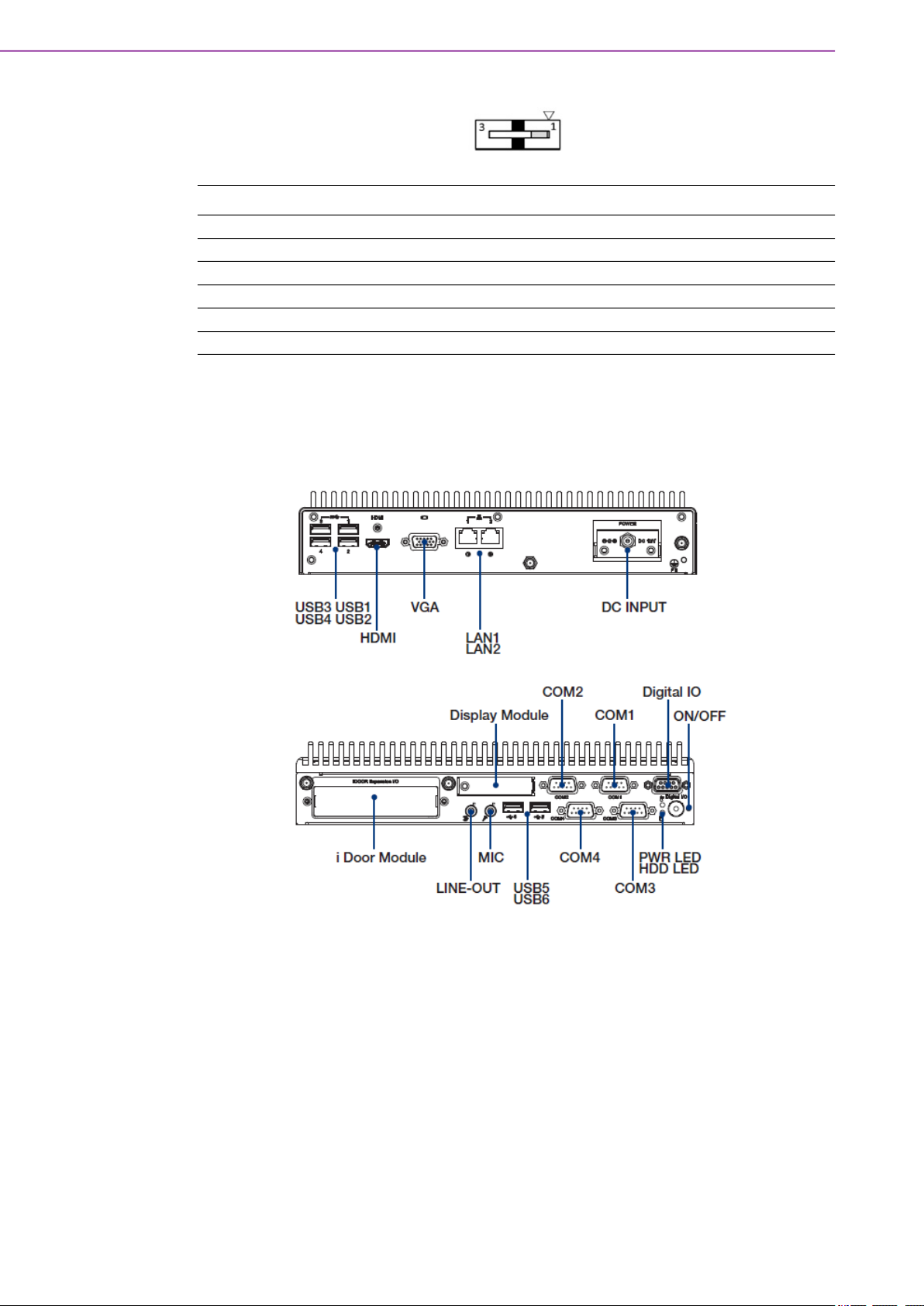
SW2 RTC Reset
Part Number 1600000071
Footprint SW_3P_CJS-1201TA1
Description CJS-1201TA1
Setting Function
1* Normal (Default)
3 RTC Reset
2.3 Connectors
2.3.1 ARK-2250 External I/O
Figure 2.2 ARK-2250 I/O
ARK-2250 User Manual 10
Page 23

2.3.1.1 Power On/Off Button
ARK-2250 has a Power On/Off button with LED indicators on the front side that show
On status (Green LED) and Off/Suspend status (Orange LED). The Power button
supports dual functions: Soft Power On/Off (Instant off or Delay 4 Seconds then off)
and Suspend.
2.3.1.2 LED Indicators
There are two LEDs on the front panel that indicate system status: The Power LED is
for system power status; and HDD LED is for HDD and compa
Chapter 2 H/W Installation
Figure 2.3 Power On/Off Button
ct flash disk status.
2.3.1.3 HDMI Connector
An integrated 19-pin receptacle connector HDMI 1.4a interface is provided. The
HDMI link supports resolutions up to 4096 x 2160 @ 24 Hz.
RS-232 RS-422 RS-485
Pin Signal Name Pin Signal Name
1 TMDS Data 2+ 2 TMDS Data 2 shield
3 TMDS Data 2- 4 TMDS Data 1+
5 TMDS Data 1 shield 6 TMDS Data 17 TMDS Data 0+ 8 TMDS Data 0 shield
9 TMDS Data 0- 10 TMDS clock+
11 TMDS clock shield 12 TMDS clock13 CEC 14 Reserved
15 SCL 16 SDA
17 DDC/CEC Ground 18 +5V
19 Hot Plug Detect
Figure 2.4 LED
Figure 2.5 HDMI Connector
11 ARK-2250 User Manual
Page 24

2.3.1.4 VGA Connector
The ARK-2250 provides a high resolution VGA interface connected by a D-sub 15pin connector to support a VGA CRT monitor. It supports display resolutions of up to
1920 x 1200 @ 60Hz (No hotplug support)
Pin Signal Name Pin Signal Name
1 Red 2 Green
3 Blue 4 NC
5 GND 6 GND
7 GND 8 GND
9 NC 10 GND
11 NC 12 DDAT
13 H-SYNC 14 V-SYNC
15 DCLK
Figure 2.6 VGA Connector
2.3.1.5 USB 3.0 Connector
The USB port USB port 1, 2, 3, 4 of ARK-2250 supports USB 3.0 interfaces, which
provides complete Plug-and-Play and hot swapping capabilities for up to 127 external devices. The USB interface complies with USB UHCI, Rev. 3.0. Please refer to
Table. 2.7 for its pin assignments. USB 3.0 connectors contain legacy pins to interface to USB 2.0 devices, and a new set of pins for USB 3.0 connectivity (both sets
reside in the same connector).
Pin Signal name Pin Signal name
1 +5V 2 USB_data3 USB_data+ 4 GND
5 SSRX- 6 SSRX+
7 GND 8 SSTX9 SSTX+
Figure 2.7 USB 3.0 Connector
Note! If your OS is Windows 7, please install the USB 3.0 driver from the Intel
website. https://downloadcenter.intel.com/download/25476/windows-7usb-3-0-creator-utility
ARK-2250 User Manual 12
Page 25

2.3.1.6 USB 2.0 Connector
ARK-2250 provides two USB interface connectors. The USB 5, 6 connectors are
used to connect any device that conforms to the USB interface. Most digital devices
conform to this standard. The USB interface supports Plug and Play capabilities.
Pin Signal name Pin Signal name
1 VCC 2 USB_data3 USB_data+ 4 GND
2.3.1.7 Ethernet Connector (LAN)
ARK-2250 is equipped with two Ethernet controllers that are fully compliant with IEEE
802.3u 10/100/1000 Mbps CSMA/CD standards. LAN1, LAN2 are all equipped with
an Intel i219/i210 Ethernet controller. The Ethernet port provides a standard RJ-45
jack connector with LED indicators on the front side to show its Active/Link status
(Green LED) and Speed status (Yellow LED).
Chapter 2 H/W Installation
Figure 2.8 USB 2.0 Connector
Figure 2.9 Ethernet Connector (LAN)
Pin 10/100/1000 BaseT Signal Name
1 TX+
2 TX3 RX+
4 MDI2+
5 MDI26 RX7 MDI3+
8 MDI3-
13 ARK-2250 User Manual
Page 26

2.3.1.8 Audio Connector
ARK-2250 offers stereo audio ports by two phone jack connectors of Line_Out,
Mic_In. The audio chip is controlled by ALC888S, and it’s compliant with Azalea standard.
Pin Audio Signal Name
1 Line out
2 Mic in
2.3.1.9 COM Connector
ARK-2250 provides four D-sub 9-pin connectors, which offers RS232/422/485 serial
communication interface ports. Default setting is RS-232, if you want to use RS-422/
485, you can find the BIOS manual and change settings.
Figure 2.10 Audio Connector
RS-232 RS-422 RS-485
Pin Signal Name Signal Name Signal Name
1 DCD Tx- DATA2 RxD Tx+ DATA+
3 TxD Rx+ NC
4 DTR Rx- NC
5 GND GND GND
6 DSR NC NC
7 RTS NC NC
8 CTS NC NC
9 RI NC NC
Note! NC represents “No Connection”.
ARK-2250 User Manual 14
Page 27

2.3.1.10 GPIO Connector
ARK-2250 provides 8-bit GPIO, please refer to the pin definition.
Pin Signal
1 DIO bit 0
2 DIO bit 1
3 DIO bit 2
4 DIO bit 3
5 DIO bit 4
6 DIO bit 5
7 DIO bit 6
8 DIO bit 7
9 GND
Chapter 2 H/W Installation
Figure 2.11 GPIO Connector
2.4 Installation
2.4.1 Memory Installation
1. Unscrew the 4 screws on the top cover. (Please use the tool in the accessory
box.)
15 ARK-2250 User Manual
Page 28

2. Remove the top cover and install the memory into the memory socket.
3. Put the top cover back.
2.4.2 HDD/SSD Installation
1. Unscrew the 4 screws on the bottom cover, and the 4 screws on both sides of
ARK-2250.
ARK-2250 User Manual 16
Page 29

2. Unscrew the 4 screws on the HDD bay.
3. Install the HDD/SSD into the HDD bay, and fix the HDD onto the bracket.
Chapter 2 H/W Installation
4. Fix the 4 screws back onto the HDD bay.
5. Put the bottom cover back and fix the 8 screws back onto the system.
17 ARK-2250 User Manual
Page 30

2.4.3 mSATA Installation
1. Unscrew the 4 screws on the bottom cover, and the 4 screws on both sides of
ARK-2250.
2. Put the mSATA module onto the mSATA slot (CN15), and fasten the 2 screws
back onto the mSATA module.
3. Put the bottom cover back and fasten the 8 screws back onto the system.
ARK-2250 User Manual 18
Page 31

2.4.4 Power Module (MIOe-PWR2) Installation (Optional)
1. Remove the 4 screws on the top cover. (Please use the tool in the accessory
box.)
Chapter 2 H/W Installation
2. Remove the 2 screws on the power bracket for the original DC jack on the front
panel.
19 ARK-2250 User Manual
Page 32

3. Unscrew the 4 screws on the bottom cover and on both sides of ARK-2250.
4. Remove the original internal power cable from the M/B.
ARK-2250 User Manual 20
Page 33

5. Link the MIOe-PWR2 internal power cable from M/B to the power board.
6. Turn to the top side, and fasten the 4 screws for the power board, and tape 3
thermal pads on the red marks.
Chapter 2 H/W Installation
7. Screw in the new power bracket for MIOe-PWR2 on the front panel.
21 ARK-2250 User Manual
Page 34

8. Put on the bottom cover and the 8 screws back onto the system.
9. Put on the top cover and the 4 screws.
2.4.5 iDoor Module Installation (Option)
Please refer to iDoor modules support on datasheet.
2.4.6 2nd Layer MIOe Module Installation (Option)
Please refer to ARK-Plus module support on datasheet.
2.4.7 Wall Mount Installation (Option)
1. Unscrew the 4 screws on both sides of ARK-2250L
2. Screw wall mount brackets on both sides pf ARK-2250L
Note! 4 x 5 mm (0.19 in) M3 type screws are provided to secure the mounting
kit and unit. Use a suitable mounting apparatus to avoid risk of injury.
Remarque! Vis de type M3, longueur 5 mm x 4 fournies pour la fixation du kit de
montage et de l'unité. Utilisez un appareil de montage approprié pour
éviter tout risque de blessure.
ARK-2250 User Manual 22
Page 35

Chapter 3
3 BIOS Settings
Page 36

Users can modify BIOS settings and control the various system features with the
AMIBIOS setup program. This chapter describes the basic navigation of ARK-2250
BIOS setup screens.
AMIBIOS ROM has a built-in setup program that allows users to modify the basic
system configuration. This information is stored in flash ROM so it retains the setup
information when the power is turned off.
3.1 Entering Setup
Turn on ARK-2250 and then press <F2> or <DEL> to enter setup menu.
3.2 Main
When users first enter BIOS setup utility, users will enter Main setup screen. Users
can always return to Main setup screen by selecting the Main tab. There are two
Main setup options. They are described in this section. The Main BIOS setup screen
is shown below.
ARK-2250 User Manual 24
Page 37

Chapter 3 BIOS Settings
The Main BIOS setup screen has two main frames. The left frame displays all the
options that can be configured. Grayed-out options cannot be configured; options in
blue can. The right frame displays the key legend.
Above the key legend is an area reserved for a test message. When an option is
selected in the left frame, it is highlighted in white. Often a test message will accompany it.
System Date / System Time
Use this option to change the system time and date. Highlight System Date or
System Time using the <Arrow> keys. Enter new values through the keyboard.
Press then <Tab> key or the <Arrow> keys to move between fields. The date
must be entered in MM/DD/YY format. The time must be entered in HH:MM:SS
format.
25 ARK-2250 User Manual
Page 38

3.3 Advanced
Select Advanced tab from the ARK-2250 setup screen to enter the Advanced BIOS
setup screen. Users can select any of the items in the left frame of the screen, such
as CPU Configuration, to go to the sub menu for that item. Users can display an
Advanced BIOS setup option by highlighting it using the <Arrow> keys. All Advanced
BIOS setup options are described in this section. The Advanced BIOS setup screens
are shown below. The sub menus are described in the following pages.
ARK-2250 User Manual 26
Page 39
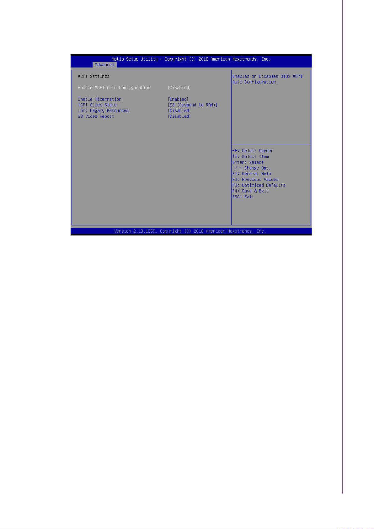
3.3.1 ACPI Settings
Chapter 3 BIOS Settings
Enable ACPI Auto Configuration
This item allows users to enable or disable BIOS ACPI auto configuration.
Enable Hibernation
This item allows users to enable or disable hibernation.
ACPI Sleep State
This item allows users to set the ACPI sleep state.
Lock Legacy Resources
This item allows users to lock legacy device resources.
S3 Video Repost
This item allows users to enable or disable S3 Video Repost.
27 ARK-2250 User Manual
Page 40

3.3.2 AMT Configuration
Intel AMT
This item allows user to enable/disable Intel® Active Management Technology
BIOS Extension.
BIOS Hotkey Pressed
This item allows users to enable/disable BIOS hotkey press.
MEBx Selection Screen
This item allows users to enable/disable MEBx selection screen.
Hide Un-Configure ME Confirmation Prompt
This item allows users to hide Un-Configure ME without password Confirmation
Prompt.
MEBx Debug Message Output
This item allows users to enable/disable MEBx debug message output.
Un-Configure ME
This item allows user to Un-Configure ME without password.
Amt Wait Timer
This item allows user to set timer to wait before sending ASF_GET_BOOT_OPTIONS.
ASF
This item allows users to enable/disable Alert Specification Format.
Activate Remote Assistance Process
This item allows users to trigger CIRA boot.
USB Provisioning of AMT
This item allows users to enable/disable of AMT USB Provisioning.
PET Progress
This item allows users to enable/disable PET Events progress to receive PET
events.
Watchdog
This item allows users to enable/disable Watchdog Timer.
ARK-2250 User Manual 28
Page 41

3.3.3 PCH-FW Configuration
Chapter 3 BIOS Settings
ME State
This item allows users to enable or disable ME State.
Firmware Update Configuration
This item allows users to enable or disable ME FW Image Re-Flash.
29 ARK-2250 User Manual
Page 42

3.3.4 Embedded Controller Configuration
The Embedded Controller Configuration displays comprehensive system temperature/voltage information.
Backlight Enable Polarity
Switch Backlight Polarity for Native or Invert
1st LVDS Backlight Control
Switch Backlight Contril to PWM or DC mode
Power Saving Mode
This item allows users to set board's power saving mode when off
Watch Dog Timer
This item allows users to enable or disable Watchdog Timer
ARK-2250 User Manual 30
Page 43

3.3.5 Trusted Computing
Chapter 3 BIOS Settings
Device Select
This item allows users to select TPM device type: 1.2 / 2.0 / Auto.
3.3.6 S5 RTC Wake Settings
31 ARK-2250 User Manual
Page 44

Wake system from S5
Enable or disable system wake on alarm event. Select fixed time, system will
wake on the hr:min:sec specified.
3.3.7 Serial Port Console Redirection
Console Redirection
This item allows users to enable or disable console redirection for Microsoft
Windows Emergency Management Services (EMS).
Console Redirection Settings
This item allows users to configure console redirection detail settings.
ARK-2250 User Manual 32
Page 45

3.3.8 CPU Configuration
Chapter 3 BIOS Settings
Hyper-threading
This item allows users to enable/disable Hyper-Threading Technology.
Active Processor Cores
This item shows number of cores to enable in each processor package.
33 ARK-2250 User Manual
Page 46

Intel Virtualization Technology
When this item is enabled, a VMM can utilize the additional hardware capabilities provided by Vanderpool Technology.
Hardware Prefetcher
This item allows users to turn on/off the MLC streamer prefetcher
Adjacent Cache Line Prefetch
This item allows users to turn on/off prefetching of adjacent cache lines.
CPU AES
This item allows users to enable/disable CPU Advanced Encryption Standard
instructions.
Boot performance mode
This item allows users to select the performance state that the BIOS will set
before OS handoff.
Intel® Speed Shift Technology
This item allows users to enable/disable Intel® Speed Shift Technology support.
Intel® SpeedStep™
This item let users to allow more than two frequency ranges to be supported.
Turbo Mode
This item allows users to enable/disable Turbo Mode.
CPU C states
This item allows users to enable or disable CPU C states.
CState Pre-Wake
When this item is disabled, it sets bit 30 of POWER_CTL MSR(0x1FC) to 1 to
disable the Cstate Pre-Wake.
Package C State limit
This item allows users to enable/disable Package C State limit.
Intel TXT(LT) Support
This item allows users to enables/disables Intel(R) TXT(LT) support.
SW Guard Extensions (SGX)
This item allows users to enable/disable Software Guard Extensions (SGX).
ARK-2250 User Manual 34
Page 47

3.3.9 Intel TXT Information
Chapter 3 BIOS Settings
This page provides TXT status information.
35 ARK-2250 User Manual
Page 48

3.3.10 Platform Misc Configuration
Native PCIE Enable
This item allows users to enable/disable PCI Express Native Support. This feature is only available in Vista.
Native ASPM
When this item is enabled, Vista will control the ASPM support for the device.
When it is disabled, the BIOS will.
ARK-2250 User Manual 36
Page 49

3.3.11 SATA Configuration
Chapter 3 BIOS Settings
SATA Controller(s)
This item allows users to enable/disable SATA Device.
SATA Mode Selection
This item determines how SATA controller(s) operate.
Aggressive LPM Support
This item enables PCH to aggressively enter link power state.
SATA Controller Speed
This item indicates the maximum speed the SATA controller can support.
Port 1/Port 2
This item allows users to enable/disable SATA Port.
SATA Device Type
This item identifies the SATA port is connected to Solid State Drive or Hard Disk
Drive.
37 ARK-2250 User Manual
Page 50

RAID0
This item allows users to enable/disable RAID0 feature.
RAID1
This item allows users to enable/disable RAID1 feature.
RAID10
This item allows users to enable/disable RAID10 feature.
ARK-2250 User Manual 38
Page 51

RAID5
This item allows users to enable/disable RAID5 feature.
Intel Rapid Recovery Technology
This item allows users to enable/disable Intel Rapid Recovery Technology.
OROM UI and BANNER
When it is enabled, the OROM UI is shown. Otherwise, no OROM banner or
information will be displayed if all disks and RAID volumes are Normal.
HDD Unlock
When it is enabled, indicates that the HDD password unlock in the OS is
enabled.
LED Locate
When it is enabled, indicates that the LED/SGPIO hardware is attached and
ping to locate feature is enabled on the OS.
IRRT Only on eSATA
When it is enabled, then only IRRT volumes can span internal and eSATA
drives.
Smart Response Technology
This item allows users to enable/disable Smart Response Technology.
OROM UI Normal Delay
This item let users to select the delay time of the OROM UI Splash Screen in a
normal status.
RST Force Form
This item allows users to enable/disable Form for Intel Rapid Storage Technology.
Chapter 3 BIOS Settings
3.3.12 Network Stack Configuration
Network Stack
Enable/Disable UEFI Network Stack.
39 ARK-2250 User Manual
Page 52

3.3.13 CSM Configuration
CSM Support
Enable/Disable CSM support
GateA20 Active
Upon Request - G20 can be disable using BIOS services. We suggest users do
not disable GA20 as this option is useful when any RT code is executed above
1MB.
Option ROM Messages
Set display mode for Option ROM.
INT19 Trap Response
BIOS reaction on INT19 trapping by Option ROM: Immediate - execute the trap
right away; Postponed - execute the trap during legacy boot.
Boot option filter
This option controls Legacy/UEFI ROM priority.
Network
Controls the execution of UEFI and Legacy PXE OpROM.
Storage
Controls the execution of UEFI and Legacy Storage OpROM.
Video
Controls the execution of UEFI and Legacy Video OpROM.
Other PCI devices
Determines OpROM execution policy for devices other than Network, Storage
or Video.
ARK-2250 User Manual 40
Page 53

3.3.14 USB Configuration
Chapter 3 BIOS Settings
Legacy USB Support
Enable Legacy USB support. AUTO option disables legacy support if no USB
devices are connected. DISABLE option keeps USB devices available only for
EFI applications.
XHI Hand-off
This is a workaround for OS without XHCI hand-off support. The XHCI ownership change should be claimed by XHCI driver.
USB Mass Storage Driver Support
Enable/Disable USB Mass Storage Device Support.
Port 60/64 Emulation
Enable/Disable Port 60/64 Emulation.
USB transfer time-out
Time-out value for control, bulk, and interrupt transfers.
Device rest time-out
USB mass storage device start until command time-out
Device power-up delay
Maximum time the device will take before it properly reports itself to the host
controller. "Auto" uses default value: for Root port it is 100ms, for a Hub port, the
delay is taken from Hub descriptor.
41 ARK-2250 User Manual
Page 54

3.3.15 First Super IO Configuration
Serial Port 1 Configuration
Set parameters of serial port 1
Serial Port 2 Configuration
Set parameters of serial port 2
Serial Port 3 Configuration
Set parameters of serial port 3
Serial Port 4 Configuration
Set parameters of serial port 4
ARK-2250 User Manual 42
Page 55

Chapter 3 BIOS Settings
Serial Port
Enable or Disable Serial Port (COM).
Change Settings
Select the optimal settings for Super IO Device.
COM Mode
Select communication type as RS-232/422/485.
43 ARK-2250 User Manual
Page 56

3.4 Chipset
System Agent (SA) Configuration
Details of System Agent Configuration
PCH-IO Configuration
Details of PCH-IO Configuration
ARK-2250 User Manual 44
Page 57

3.4.1 System Agent Configuration
Chapter 3 BIOS Settings
Above 4GB MMIO BIOS assignment
This item allows users to enable/disable above 4GB Memory MappedIO BIOS
assignment. This is disabled automatically when Aperture Size is set to
2048MB.
45 ARK-2250 User Manual
Page 58
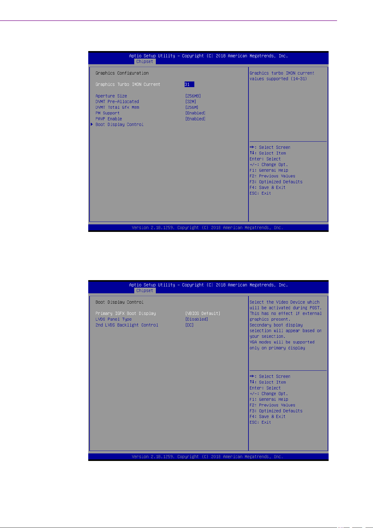
3.4.1.1 Graphic Configuration
Graphics Turbo IMON Current
Graphics turbo IMON current values supported (14-31).
Boot Display Control
– Primary IGFX Boot Display
This item let users to select the Video Device which will be activated during
POST.
ARK-2250 User Manual 46
Page 59

– LVDS Panel Type
This item let user to select LCD Panel Type.
– 2nd LVDS Backlight Control
This item let users to switch Backlight Control for PWM or DC mode.
3.4.1.2 Memory Configuration
Chapter 3 BIOS Settings
Maximum Memory Frequency
This item let users to set Maximum Memory Frequency Selections in Mhz.
Max TOLUD
This item let users to set Maximum Value of TOLUD. Dynamic assignment
would adjust TOLUD automatically based on largest MMIO length of installed
graphic controller.
SA GV
This item is System Agent Geyserville. Fixed Low/High: SA GV disabled, MRC
only runs tasks from Low or High point.
SA GV Low Freq
Set frequency for low point. Default 1067 for LPDDR3/DDR3, 1333 for DDR4.
Energy Performance Gain
This item allows users to enable/disable Energy Performance Gain.
Memory Remap
This item allows users to enable/disable Memory Remap above 4GB.
47 ARK-2250 User Manual
Page 60
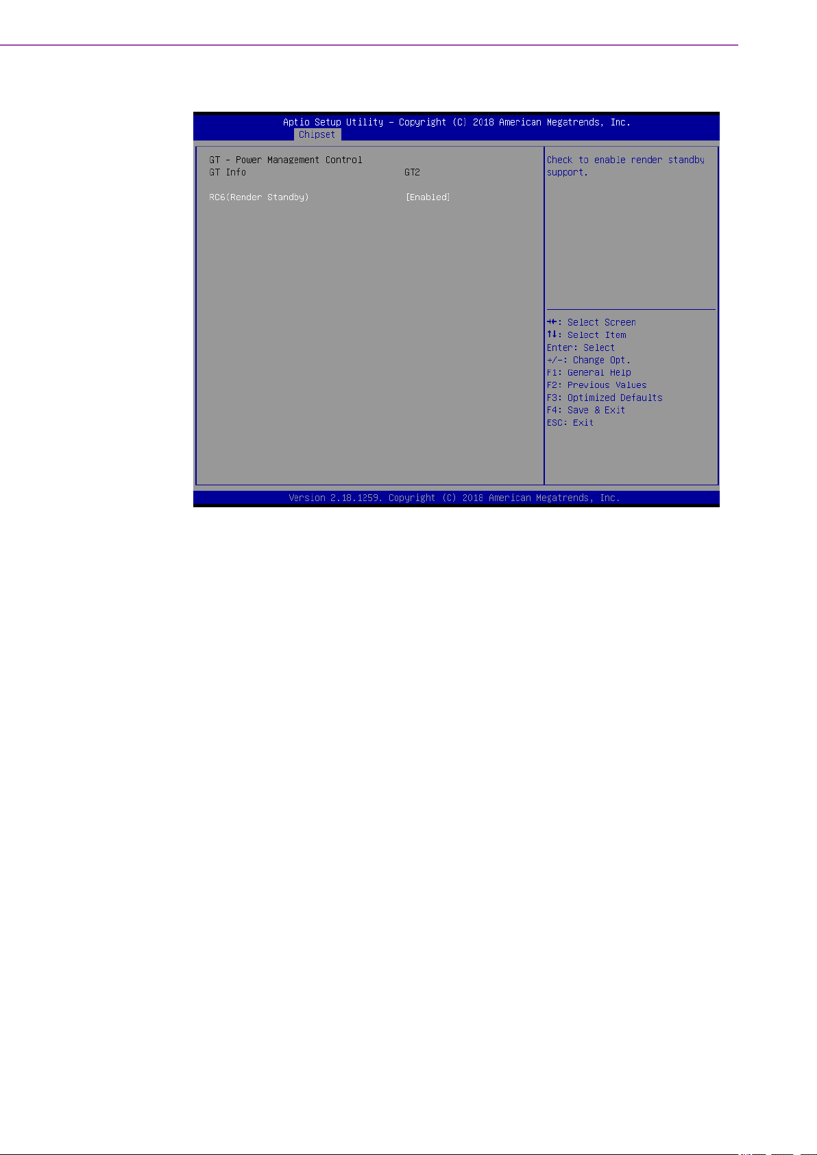
3.4.1.3 GT - Power Management Control
– RC6 (Render Standby)
This item checks to enable render standby support.
ARK-2250 User Manual 48
Page 61

3.4.2 PCH-IO Configuration
Chapter 3 BIOS Settings
Mini PCIE/mSATA Selection
This item let users to select to enable Mini PCIE or mSATA for connector
(CN15).
PCH LAN Controller
This item allows users to enable/disable onboard NIC.
LAN Option ROM
This item allows users to enable/disable LAN option ROM
Wake on LAN
This item allows users to enable/disable integrated LAN to wake the system.
Onboard LAN2 Controller
This item allows users to enable/disable onboard LAN2 Controller.
PCIE Wake
This item allows users to enable/disable PCIE to wake the system from S5.
High Precision Timer
This item allows users to enable/disable the High Precision Event Timer.
State After G3
This item Specifies what state to go to when power is re-applied after a power
failure (G3 state).
49 ARK-2250 User Manual
Page 62

3.4.2.1 PCI Express Configuration
PCI Express Clock Gating
This item allows users to enable/disable PCI Express Clock Gating
DMI Link ASPM Control
This item allows users to enable/disable DMI Link ASPM Control
PCI Express Root Port 1
– PCI Express Root Port\
ARK-2250 User Manual 50
Page 63

– ASPM Support
– L1 Substates
– PCIe Speed
– Detect Non-Compliance Device
3.4.2.2 USB Configuration
Chapter 3 BIOS Settings
USB Precondition
Precondition work on USB host controller and root ports for faster enumeration.
XHCI Disable Compliance Mode
This item provides options to disable Compliance Mode. Default is FALSE to not
disable Compliance Mode. Set TRUE to disable Compliance Mode.
USB Port Disable Override
This item allows users to enable/disable the corresponding USB port from
reporting a Device Connection to the controller.
51 ARK-2250 User Manual
Page 64

3.4.2.3 BIOS Security Configuration
RTC Lock
This item allows users to enable/disable RTC Lock.
BIOS Lock
This item allows users to enable/disable the PCH BIOS Lock Enable (BLE bit)
feature.
ARK-2250 User Manual 52
Page 65

3.4.2.4 HD Audio Configuration
Chapter 3 BIOS Settings
HD Audio
This item allows users to enable/disable HD Audio
3.4.2.5 SB Porting Configuration
53 ARK-2250 User Manual
Page 66

SATA RAID ROM
This item allows users to switch between Legacy ROM/ UEFI Driver/ Both.
Legacy ROM: Legacy option ROM. UEFI Driver: UEFI Raid Driver. Both: Run
the legacy Option ROM and UEFI driver.
3.5 Security Setup
Select Security Setup from the ARK-2250 Setup main BIOS setup menu. All Security
Setup options, such as password protection is described in this section. To access
the sub menu for the following items, select the item and press <Enter>:
Change Administrator / User Password
Select this option and press <ENTER> to access the sub menu, and then type
in the password.
ARK-2250 User Manual 54
Page 67

3.6 Boot Settings
Chapter 3 BIOS Settings
Setup Prompt Timeout
Number of seconds that the firmware will wait before initiating the original
default boot selection. A value of 0 indicates that the default boot selection is to
be initiated immediately on boot. A value of 65535 (0xFFFF) indicates that firmware will wait for user input before booting. This means the default boot selection is not automatically started by the firmware.
Bootup NumLock State
Select the keyboard NumLock state.
Quiet Boot
Enables or disables Quiet Boot option.
Boot Option #1
Sets the system boot order.
55 ARK-2250 User Manual
Page 68

3.7 Save & Exit
Save Changes and Exit
This item allows you to exit system setup after saving the changes.
Discard Changes and Exit
This item allows you to exit system setup without saving any changes.
Save Changes and Reset
This item allows you to reset the system after saving the changes.
Discard Changes and Reset
This item allows you to rest system setup without saving any changes.
Save Changes
This item allows you to save changes done so far to any of the options.
Discard Changes
This item allows you to discard changes done so far to any of the options.
Restore Defaults
This item allows you to restore/load default values for all the options.
Save as User Defaults
This item allows you to save the changes done so far as user defaults.
Restore User Defaults
This item allows you to restore the user defaults to all the options.
Boot Override
Boot device select can override your boot priority.
ARK-2250 User Manual 56
Page 69

Appendix A
A Watchdog Timer
Sample Code
Page 70

A.1 EC Watchdog Timer sample code
EC_Command_Port = 0x29Ah
EC_Data_Port = 0x299h
Write EC HW ram = 0x89
Watch dog event flag = 0x57
Watchdog reset delay time = 0x5E
Reset event = 0x04
Start WDT function = 0x28
====================================================
.model small
.486p
.stack 256
.data
.code
org 100h
.STARTup
mov dx, EC_Command_Port
mov al,89h ; Write EC HW ram.
out dx,al
mov dx, EC_Command_Port
mov al, 5Fh ; Watchdog reset delay time low byte (5Eh is high byte) index.
out dx,al
mov dx, EC_Data_Port
mov al, 30h ;Set 3 seconds delay time.
out dx,al
mov dx, EC_Command_Port
mov al,89h ; Write EC HW ram.
out dx,al
mov dx, EC_Command_Port
mov al, 57h ; Watch dog event flag.
out dx,al
mov dx, EC_Data_Port
mov al, 04h ; Reset event.
out dx,al
mov dx, EC_Command_Port
mov al,28h ; start WDT function.
out dx,al
.exit
END
ARK-2250 User Manual 58
Page 71

Appendix A Watchdog Timer Sample Code
59 ARK-2250 User Manual
Page 72

www.advantech.com
Please verify specifications before quoting. This guide is intended for reference
purposes only.
All product specifications are subject to change without notice.
No part of this publication may be reproduced in any form or by any means,
electronic, photocopying, recording or otherwise, without prior written permission from the publisher.
All brand and product names are trademarks or registered trademarks of their
respective companies.
© Advantech Co., Ltd. 2021
 Loading...